brake light VAUXHALL ADAM 2014.5 Owner's Manual
[x] Cancel search | Manufacturer: VAUXHALL, Model Year: 2014.5, Model line: ADAM, Model: VAUXHALL ADAM 2014.5Pages: 217, PDF Size: 6.68 MB
Page 13 of 217

In brief11
1Power windows .....................27
2 Exterior mirrors .....................25
3 Cruise control .....................130
Speed limiter ....................... 131
4 Side air vents ...................... 117
5 Turn and lane-change
signals, headlight flash,
low beam and high beam ....105
Exit lighting ......................... 108
Parking lights ...................... 105
Buttons for Driver
Information Centre ................87
6 Instruments .......................... 77
7 Steering wheel controls .......69
8 Driver Information Centre ...... 87
9 Windscreen wiper,
windscreen washer
system, headlight washer
system, rear wiper, rear
washer system ......................71
10 Central locking system ..........20
City mode ............................ 128
Fuel selector ......................... 78Eco button for stop-start
system ................................. 121
Parking assist ..................... 133
Seat heating .......................... 34
Heated steering wheel ..........70
11 Info-Display .......................... 91
12 Hazard warning flashers ....104
Control indicator for airbag deactivation .......................... 83
Control indicator for front
passenger seat belt .............82
13 Anti-theft alarm system
status LED ........................... 24
14 Centre air vents .................. 117
15 Side air vents passenger
side ..................................... 117
16 Glovebox .............................. 50
Fuse box ............................ 167
17 Climate control system ........ 110
18 Power outlet .......................... 76
19 AUX input, USB input ...........1020Selector lever, manual
transmission ....................... 124
21 Parking brake ......................126
22 Ignition switch with
steering wheel lock ............120
23 Horn ..................................... 70
Driver airbag ........................ 40
24 Bonnet release lever ..........152
25 Steering wheel adjustment ..69
26 Light switch ........................ 102
Headlight range
adjustment ......................... 104
Rear fog light ...................... 105
Brightness of instrument
panel illumination and
ambient light ....................... 106
Page 18 of 217
16In briefTransmission
Manual transmission
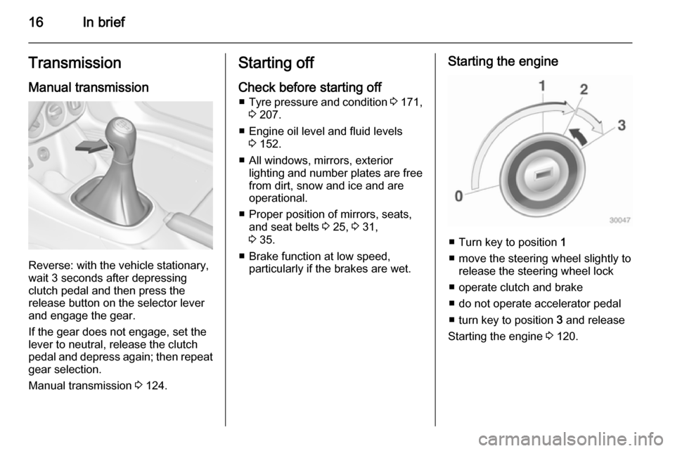
Reverse: with the vehicle stationary,
wait 3 seconds after depressing
clutch pedal and then press the
release button on the selector lever
and engage the gear.
If the gear does not engage, set the
lever to neutral, release the clutch
pedal and depress again; then repeat
gear selection.
Manual transmission 3 124.
Starting off
Check before starting off ■ Tyre pressure and condition 3 171,
3 207.
■ Engine oil level and fluid levels 3 152.
■ All windows, mirrors, exterior lighting and number plates are free
from dirt, snow and ice and are
operational.
■ Proper position of mirrors, seats, and seat belts 3 25, 3 31,
3 35.
■ Brake function at low speed, particularly if the brakes are wet.Starting the engine
■ Turn key to position 1
■ move the steering wheel slightly to release the steering wheel lock
■ operate clutch and brake
■ do not operate accelerator pedal
■ turn key to position 3 and release
Starting the engine 3 120.
Page 85 of 217
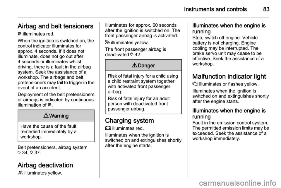
Instruments and controls83Airbag and belt tensioners
v illuminates red.
When the ignition is switched on, the control indicator illuminates for
approx. 4 seconds. If it does not
illuminate, does not go out after
4 seconds or illuminates whilst
driving, there is a fault in the airbag
system. Seek the assistance of a
workshop. The airbags and belt
pretensioners may fail to trigger in the event of an accident.
Deployment of the belt pretensioners
or airbags is indicated by continuous
illumination of v.9 Warning
Have the cause of the fault
remedied immediately by a
workshop.
Belt pretensioners, airbag system
3 34, 3 37.
Airbag deactivation
V illuminates yellow.
Illuminates for approx. 60 seconds
after the ignition is switched on. The
front passenger airbag is activated.
* illuminates yellow.
The front passenger airbag is
deactivated 3 42.9 Danger
Risk of fatal injury for a child using
a child restraint system together
with activated front passenger
airbag.
Risk of fatal injury for an adult
person with deactivated front
passenger airbag.
Charging system
p illuminates red.
Illuminates when the ignition is
switched on and extinguishes shortly
after the engine starts.
Illuminates when the engine is
running
Stop, switch off engine. Vehicle
battery is not charging. Engine
cooling may be interrupted. The
brake servo unit may cease to be
effective. Seek the assistance of a
workshop.
Malfunction indicator light
Z illuminates or flashes yellow.
Illuminates when the ignition is
switched on and extinguishes shortly
after the engine starts.
Illuminates when the engine isrunning
Fault in the emission control system. The permitted emission limits may be
exceeded. Seek the assistance of a
workshop immediately.
Page 88 of 217
86Instruments and controlsEngine oil pressure
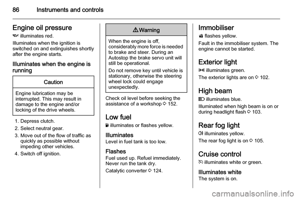
I illuminates red.
Illuminates when the ignition is
switched on and extinguishes shortly
after the engine starts.
Illuminates when the engine isrunningCaution
Engine lubrication may be
interrupted. This may result in
damage to the engine and/or
locking of the drive wheels.
1. Depress clutch.
2. Select neutral gear.
3. Move out of the flow of traffic as quickly as possible without
impeding other vehicles.
4. Switch off ignition.
9 Warning
When the engine is off,
considerably more force is needed
to brake and steer. During an
Autostop the brake servo unit will still be operational.
Do not remove key until vehicle is stationary, otherwise the steeringwheel lock could engage
unexpectedly.
Check oil level before seeking the
assistance of a workshop 3 152.
Low fuel
Y illuminates or flashes yellow.
Illuminates
Level in fuel tank is too low.
Flashes Fuel used up. Refuel immediately.
Never run the tank dry.
Catalytic converter 3 124.
Immobiliser
d flashes yellow.
Fault in the immobiliser system. The
engine cannot be started.
Exterior light8 illuminates green.
The exterior lights are on 3 102.
High beam
C illuminates blue.
Illuminated when high beam is on or
during headlight flash 3 103.
Rear fog light
r illuminates yellow.
The rear fog light is on 3 105.
Cruise control m illuminates white or green.
Illuminates white The system is on.
Page 95 of 217
Instruments and controls93Vehicle messages
Messages are indicated mainly in the
Driver Information Centre (DIC), in
some cases together with a warning and signal buzzer.
Press the SET/CLR button, the
MENU button or turn the adjuster
wheel to confirm a message.
Vehicle messages on the
Midlevel-Display
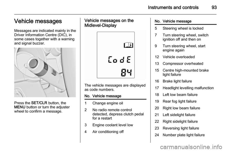
The vehicle messages are displayed
as code numbers.
No.Vehicle message1Change engine oil2No radio remote control
detected, depress clutch pedal
for a restart3Engine coolant level low4Air conditioning offNo.Vehicle message5Steering wheel is locked7Turn steering wheel, switch
ignition off and then on9Turn steering wheel, start
engine again12Vehicle overloaded13Compressor overheated15Centre high-mounted brake
light failure16Brake light failure17Headlight levelling malfunction18Left low beam failure19Rear fog light failure20Right low beam failure21Left sidelight failure22Right sidelight failure23Reversing light failure24Number plate light failure
Page 97 of 217

Instruments and controls95
■ Lighting, bulb replacement
■ Wiper/washer system
■ Doors, windows
■ Radio remote control
■ Seat belts
■ Airbag systems
■ Engine and transmission
■ Tyre pressure
■ Vehicle battery
Vehicle messages on the
Colour-Info-Display Some important messages appear
additionally in the
Colour-Info-Display. Some
messages only pop up for a few
seconds.
Warning chimes When starting the engine or
whilst driving
Only one warning chime will sound at a time.The warning chime regarding
unfastened seat belts has priority
over any other warning chime.
■ If seat belt is not fastened.
■ If a door or the tailgate is not fully closed when starting off.
■ If a certain speed is exceeded with parking brake applied.
■ If a programmed speed is exceeded.
■ If a warning message or a warning code appears in the Driver
Information Centre or Graphic-Info- Display.
■ If the parking assist or advanced parking assist detects an object.
■ If the reverse gear is engaged and the rear end carrier extended.
When the vehicle is parked and/ or the driver's door is opened ■ When the key is in the ignition switch.
■ With exterior lights on.During an Autostop ■ If the driver's door is opened.
Battery voltage When the vehicle battery voltage is
running low, a warning message or
warning code 174 will appear in the
Driver Information Centre.
1. Switch off immediately electrical consumers which are not requiredfor a safe ride, such as seat
heating, heated rear window or
other main consumers.
2. Charge the vehicle battery by driving continuously for a while or
by using a charging device.
The warning message or warning
code will disappear after the engine has been started two times
consecutively without voltage drop.
If the vehicle battery cannot be
recharged, have the cause of the fault remedied by a workshop.
Page 127 of 217
Driving and operating125Caution
It is not advisable to drive with thehand resting on the selector lever.
Brakes
The brake system comprises two independent brake circuits.
If a brake circuit fails, the vehicle can
still be braked using the other brake
circuit. However, braking effect is
achieved only when the brake pedal
is depressed firmly. Considerably
more force is needed for this. The
braking distance is extended. Seek the assistance of a workshop before
continuing your journey.
When the engine is not running, the
support of the brake servo unit
disappears once the brake pedal has been depressed once or twice.
Braking effect is not reduced, but
braking requires significantly greater
force. It is especially important to bear
this in mind when being towed.
Control indicator R 3 84.
Antilock brake system
Antilock brake system (ABS)
prevents the wheels from locking.ABS starts to regulate brake pressure as soon as a wheel shows a tendency to lock. The vehicle remains
steerable, even during hard braking.
ABS control is made apparent
through a pulse in the brake pedal
and the noise of the regulation
process.
For optimum braking, keep the brake
pedal fully depressed throughout the
braking process, despite the fact that
the pedal is pulsating. Do not reduce
the pressure on the pedal.
After starting off the system performs a self-test which may be audible.
Control indicator u 3 84.
Adaptive brake light
During full braking, all three brake
lights flash for the duration of ABS
control.
Page 128 of 217
126Driving and operating
Fault9Warning
If there is a fault in the ABS, the
wheels may be liable to lock due
to braking that is heavier than
normal. The advantages of ABS are no longer available. During
hard braking, the vehicle can no longer be steered and may
swerve.
Have the cause of the fault remedied
by a workshop.
Parking brake
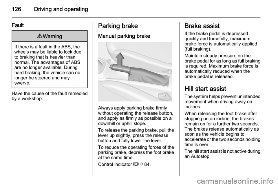
Manual parking brake
Always apply parking brake firmly
without operating the release button,
and apply as firmly as possible on a
downhill or uphill slope.
To release the parking brake, pull the lever up slightly, press the release
button and fully lower the lever.
To reduce the operating forces of the
parking brake, depress the foot brake
at the same time.
Control indicator R 3 84.
Brake assist
If the brake pedal is depressed
quickly and forcefully, maximum
brake force is automatically applied
(full braking).
Maintain steady pressure on the
brake pedal for as long as full braking
is required. Maximum brake force is
automatically reduced when the
brake pedal is released.
Hill start assist
The system helps prevent unintended movement when driving away on
inclines.
When releasing the foot brake after
stopping on an incline, the brakes
remain on for a further two seconds.
The brakes release automatically as
soon as the vehicle begins to
accelerate or the two seconds holding
time is over.
The hill start assist is not active during
an Autostop.
Page 129 of 217

Driving and operating127Ride control systems
Traction Control system
The Traction Control system (TC) is a component of the Electronic Stability
Control (ESC).
TC improves driving stability when
necessary, regardless of the type of
road surface or tyre grip, by
preventing the drive wheels from
spinning.
As soon as the drive wheels starts to
spin, engine output is reduced and
the wheel spinning the most is braked
individually. This considerably
improves the driving stability of the
vehicle on slippery road surfaces.
TC is operational after each engine
start as soon as the control indicator
b extinguishes.
When TC operates b flashes.
9 Warning
Do not let this special safety
feature tempt you into taking risks
when driving.
Adapt speed to the road
conditions.
Fault
If there is a fault in the system the
control indicator b lights up
continuously and a message or a
warning code appears in the Driver
Information Centre. The system is not
operational.
Have the cause of the fault remedied
by a workshop.
Electronic Stability Control Electronic Stability Control (ESC)
improves driving stability when
necessary, regardless of the type of
road surface or tyre grip. It also
prevents the drive wheels from
spinning. ESC operates in
combination with the Traction Control system (TC).
As soon as the vehicle starts to
swerve (understeer/oversteer),
engine output is reduced and the
wheels are braked individually. This
considerably improves the driving
stability of the vehicle on slippery road
surfaces.
Page 163 of 217
Vehicle care161
Version with subwoofer box:remove load compartment floor
cover, on right side also remove
the tool box to gain access to the
cover 3 64.
Version with storage box: remove
storage box to gain access to the
cover 3 62.
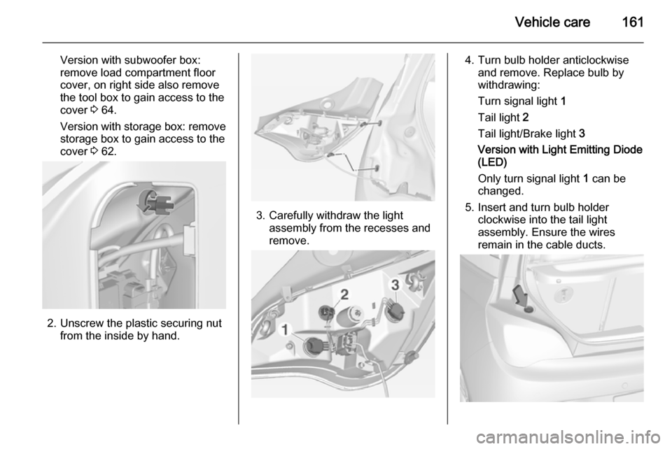
2. Unscrew the plastic securing nut
from the inside by hand.
3. Carefully withdraw the lightassembly from the recesses and
remove.
4. Turn bulb holder anticlockwise and remove. Replace bulb by
withdrawing:
Turn signal light 1
Tail light 2
Tail light/Brake light 3
Version with Light Emitting Diode (LED)
Only turn signal light 1 can be
changed.
5. Insert and turn bulb holder clockwise into the tail light
assembly. Ensure the wires
remain in the cable ducts.