ESP VAUXHALL ADAM 2014 Owner's Guide
[x] Cancel search | Manufacturer: VAUXHALL, Model Year: 2014, Model line: ADAM, Model: VAUXHALL ADAM 2014Pages: 217, PDF Size: 6.68 MB
Page 137 of 217
Driving and operating135
In the Colour-Info-Display, distance isdisplayed by coloured zones in front
of or behind the vehicle.
The distance indication in the Driver
Information Centre can be inhibited
by vehicle messages with a higher
priority. After approving the message
by pressing the SET/CLR button on
the turn signal lever, distance
indication appears again.
Fault
In the event of a fault or if the system
does not work temporarily, e.g.
because of high external noise level
or other interference factors, the LED in the button flashes for 3 seconds
and then extinguishes. Control
indicator r illuminates in the
instrument cluster 3 84 and a
message pops-up in the Driver
Information Centre.
Vehicle messages 3 92.Advanced parking assist9 Warning
It is the driver who bears full
responsibility for accepting the
parking slot suggested by the
system and the parking
manoeuvre.
Always check the sourrounding
area in all directions when using
advanced parking assist.
The advanced parking assist
measures a suitable parking slot
while passing, calculates the
trajectory and automatically steers
the vehicle into a parallel or
perpendicular parking slot.
Instructions are given by the Driver
Information Centre or the Colour-Info-
Display supported by acoustic
signals. The driver must control
acceleration, braking and gear
shifting, while steering is done
automatically.
Advanced parking assist can only be
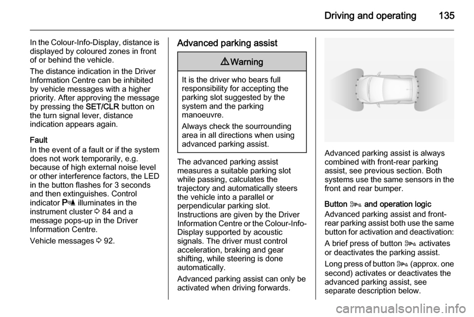
activated when driving forwards.Advanced parking assist is always
combined with front-rear parking assist, see previous section. Both
systems use the same sensors in the front and rear bumper.
Button D and operation logic
Advanced parking assist and front-
rear parking assist both use the same button for activation and deactivation:
A brief press of button D activates
or deactivates the parking assist.
Long press of button D (approx. one
second) activates or deactivates the
advanced parking assist, see
separate description below.
Page 143 of 217

Driving and operating141correct distance indication in the
upper part of these vehicles
cannot be guaranteed.
Objects with a very small reflection
cross-section, e.g. objects of
narrow size or soft materials, may
not be detected by the system.
Parking assist systems do not
detect objects outside the
detection range.
Notice
It is possible that the sensor detects a non-existing object caused by
echo disturbance from external
acoustic noise or mechanical
misalignments (sporadic false
warnings might happen).
Make sure that the front license plate
is properly mounted (not bent and no
gaps to the bumper on the left or
right side) and the sensors are well
in place.
Advanced parking assist system
may not respond to changes in the
available parking space after
initiating a parking manoeuvre. The
system may recognize an entry, a
gateway, a courtyard or even a crossing as parking slot. After
selecting reverse gear the system
would start a parking manoeuvre.
Take care of the availability of the
suggested parking slot.
Surface irregularities, e.g. on
construction zones, are not detected by the system. The driver accepts
responsibility.
Notice
If engaging a forward gear and
exceeding a certain speed, the rear
parking assist will be deactivated
when the rear carrier system is
extended.
If engaging reverse at first, the
parking assist will detect the rear
carrier system and provide a buzzing
sound. Press r or D briefly to
deactivate the parking assist.
Notice
After production, the system
requires a calibration. For optimal
parking guidance, a driving distance
of at least 6 miles, including a
number of bends, is required.Side blind spot alert
The Side blind spot alert system
detects and reports objects on either
side of the vehicle, within a specified
"blind spot" zone. The system alerts visually in each exterior mirror, when
detecting objects that may not be
visible in the interior and exterior
mirrors.
Side blind spot alert uses some of the advanced parking assist sensors
which are located in the front and rear bumper on both sides of the vehicle.9 Warning
Side blind spot alert does not
replace driver vision.
The system does not detect: ■ Vehicles outside the side blind zones which may be rapidly
approaching.
■ Pedestrians, cyclists or animals.
Before changing a lane, always
check all mirrors, look over the
shoulder and use the turn signal.
Page 154 of 217
152Vehicle careCaution
It is the owner's responsibility to
maintain the proper level of an
appropriate quality oil in the
engine.
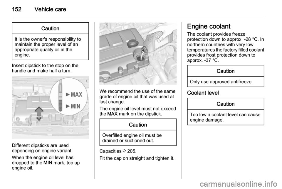
Insert dipstick to the stop on the
handle and make half a turn.
Different dipsticks are used
depending on engine variant.
When the engine oil level has
dropped to the MIN mark, top up
engine oil.
We recommend the use of the same
grade of engine oil that was used at
last change.
The engine oil level must not exceed
the MAX mark on the dipstick.
Caution
Overfilled engine oil must be
drained or suctioned out.
Capacities 3 205.
Fit the cap on straight and tighten it.
Engine coolant
The coolant provides freeze
protection down to approx. -28 °C. In
northern countries with very low
temperatures the factory filled coolant
provides frost protection down to
approx. -37 °C.Caution
Only use approved antifreeze.
Coolant level
Caution
Too low a coolant level can cause engine damage.
Page 161 of 217
Vehicle care159Front turn signal lights
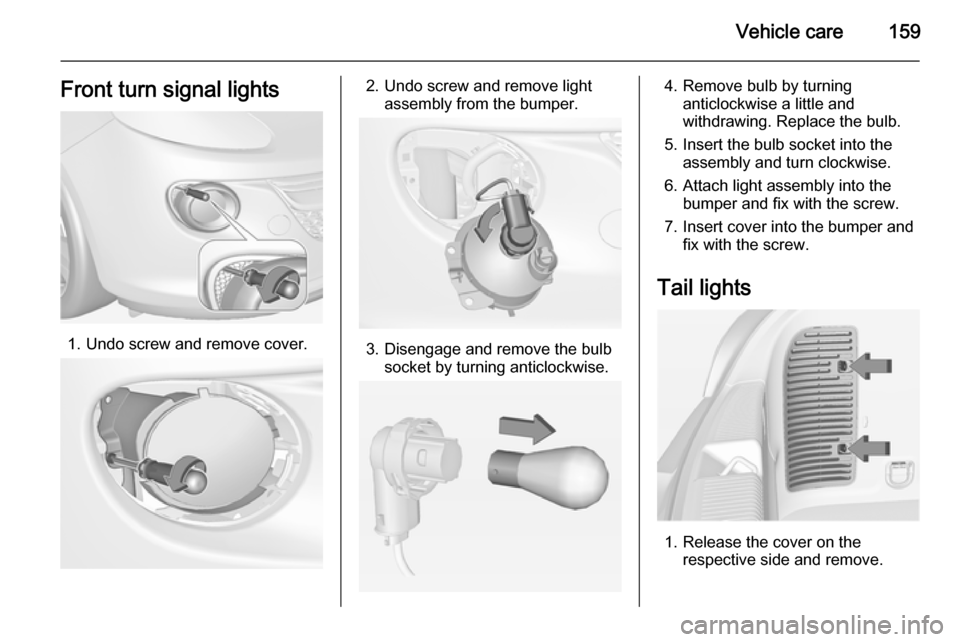
1. Undo screw and remove cover.
2. Undo screw and remove lightassembly from the bumper.
3. Disengage and remove the bulbsocket by turning anticlockwise.
4. Remove bulb by turninganticlockwise a little and
withdrawing. Replace the bulb.
5. Insert the bulb socket into the assembly and turn clockwise.
6. Attach light assembly into the bumper and fix with the screw.
7. Insert cover into the bumper and fix with the screw.
Tail lights
1. Release the cover on the respective side and remove.
Page 166 of 217
164Vehicle careElectrical systemFuses
Data on the replacement fuse must
match the data on the defective fuse.
There are two fuse boxes in the
vehicle:
■ in the front left of the engine compartment,
■ in left-hand drive vehicles behind the light switch, or, in right-hand
drive vehicles, behind the
glovebox.
Before replacing a fuse, turn off the
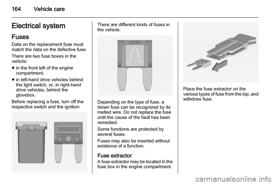
respective switch and the ignition.There are different kinds of fuses in
the vehicle.
Depending on the type of fuse, a
blown fuse can be recognized by its
melted wire. Do not replace the fuse until the cause of the fault has been
remedied.
Some functions are protected by
several fuses.
Fuses may also be inserted without existence of a function.
Fuse extractor A fuse extractor may be located in the fuse box in the engine compartment.
Place the fuse extractor on the
various types of fuse from the top, and
withdraw fuse.
Page 173 of 217
Vehicle care171Tyre designationsE.g. 195/55 R 16 95 H195=Tyre width, mm55=Cross-section ratio (tyre
height to tyre width), %R=Belt type: RadialRF=Type: RunFlat16=Wheel diameter, inches95=Load index e.g. 95 is
equivalent to 690 kgH=Speed code letter
Speed code letter:
Q=up to 100 mphS=up to 112 mphT=up to 118 mphH=up to 130 mphV=up to 150 mphW=up to 168 mph
Tyre pressure
Check the pressure of cold tyres at
least every 14 days and before any
long journey. Do not forget the spare
wheel. This also applies to vehicles
with tyre pressure monitoring system.
Unscrew the valve cap.
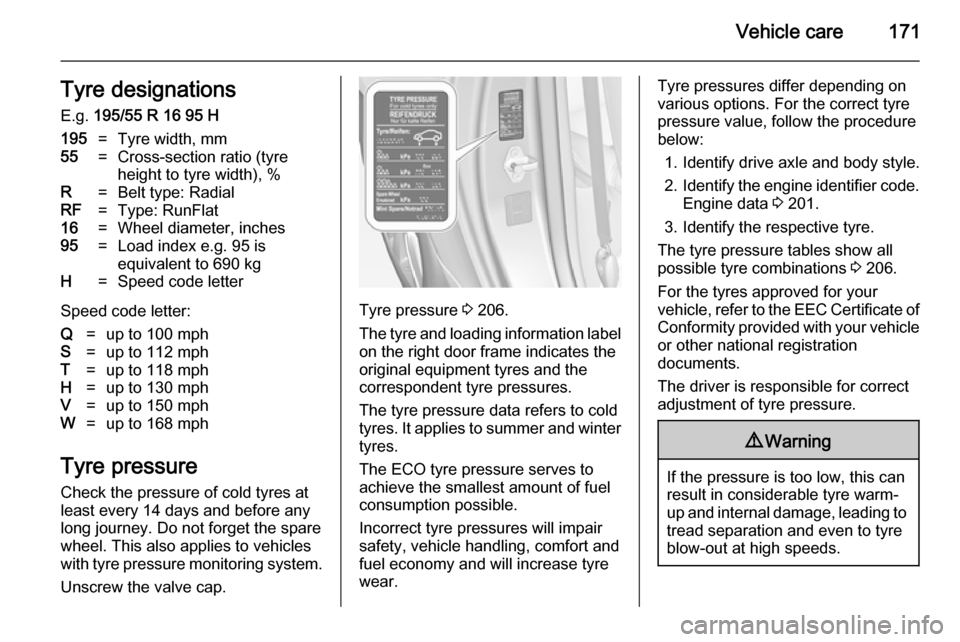
Tyre pressure 3 206.
The tyre and loading information label on the right door frame indicates the
original equipment tyres and the
correspondent tyre pressures.
The tyre pressure data refers to cold
tyres. It applies to summer and winter tyres.
The ECO tyre pressure serves to
achieve the smallest amount of fuel
consumption possible.
Incorrect tyre pressures will impair
safety, vehicle handling, comfort and fuel economy and will increase tyre
wear.
Tyre pressures differ depending on
various options. For the correct tyre
pressure value, follow the procedure
below:
1. Identify drive axle and body style.
2. Identify the engine identifier code.
Engine data 3 201.
3. Identify the respective tyre.
The tyre pressure tables show all possible tyre combinations 3 206.
For the tyres approved for your
vehicle, refer to the EEC Certificate of Conformity provided with your vehicle
or other national registration
documents.
The driver is responsible for correct
adjustment of tyre pressure.9 Warning
If the pressure is too low, this can
result in considerable tyre warm-
up and internal damage, leading to tread separation and even to tyre
blow-out at high speeds.
Page 174 of 217
172Vehicle care
If the tyre pressure must be reduced
or increased on a vehicle with tyre
pressure monitoring system, switch off ignition. After adjusting tyre
pressure switch on ignition and select the relevant setting on the page Tyre
load in the Driver Information Centre,
3 86.
Tyre pressure monitoring
system The tyre pressure monitoring system
checks the pressure of all four tyres
once a minute when vehicle speed
exceeds a certain limit.Caution
Tyre pressure monitoring system
warns only about low tyre pressure condition and does not replace
regular tyre maintenance by the
driver.
All wheels must be equipped with pressure sensors and the tyres must
have the prescribed pressure.
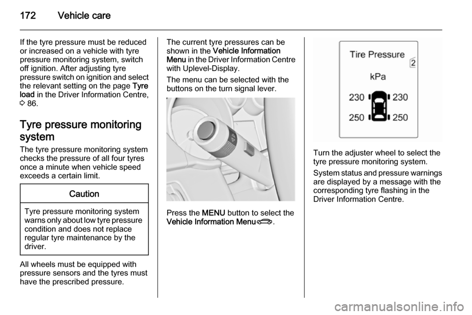
The current tyre pressures can be
shown in the Vehicle Information
Menu in the Driver Information Centre
with Uplevel-Display.
The menu can be selected with the
buttons on the turn signal lever.
Press the MENU button to select the
Vehicle Information Menu X.
Turn the adjuster wheel to select the
tyre pressure monitoring system.
System status and pressure warnings
are displayed by a message with the
corresponding tyre flashing in the
Driver Information Centre.
Page 177 of 217

Vehicle care175Changing tyre and wheel
size If tyres of a different size than those
fitted at the factory are used, it may be
necessary to reprogramme the
speedometer as well as the nominal
tyre pressure and make other vehicle modifications.
After converting to a different tyre
size, have the label with tyre
pressures replaced.9 Warning
Use of unsuitable tyres or wheels
may lead to accidents and will
invalidate the vehicle type
approval.
Wheel covers
Wheel covers and tyres that are
factory approved for the respective
vehicle and comply with all of the
relevant wheel and tyre combination requirements must be used.
If the wheel covers and tyres used are
not factory approved, the tyres must
not have a rim protection ridge.
Wheel covers must not impair brake
cooling.9 Warning
Use of unsuitable tyres or wheel
covers could lead to sudden
pressure loss and thereby
accidents.
Tyre chains
Tyre chains are only permitted on the
front wheels.
Always use fine mesh chains that add no more than 10 mm to the tyre tread
and the inboard sides (including chain lock).9 Warning
Damage may lead to tyre blowout.
Tyre chains are only permitted on
tyres of size 175/70 R 14,
185/60 R 15, 185/65 R 15 and 195/55 R 16.
Tyre chains are not permitted on tyres of size 215/45 R 17 and 225/35 R 18 .
The use of tyre chains is not permitted
on the temporary spare wheel.
Tyre repair kit
Minor damage to the tyre tread can be
repaired with the tyre repair kit.
Do not remove foreign bodies from
the tyres.
Page 183 of 217
Vehicle care181
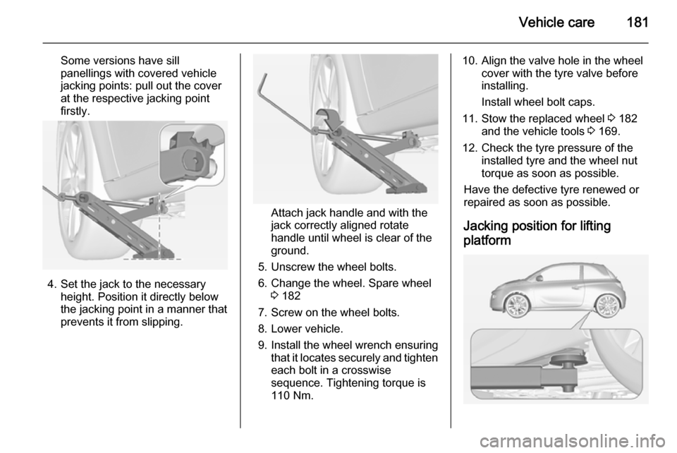
Some versions have sill
panellings with covered vehicle
jacking points: pull out the cover
at the respective jacking point
firstly.
4. Set the jack to the necessary height. Position it directly below
the jacking point in a manner that
prevents it from slipping.
Attach jack handle and with the
jack correctly aligned rotate handle until wheel is clear of theground.
5. Unscrew the wheel bolts.
6. Change the wheel. Spare wheel 3 182
7. Screw on the wheel bolts.
8. Lower vehicle.
9. Install the wheel wrench ensuring that it locates securely and tighten
each bolt in a crosswise
sequence. Tightening torque is
110 Nm.
10. Align the valve hole in the wheel cover with the tyre valve before
installing.
Install wheel bolt caps.
11. Stow the replaced wheel 3 182
and the vehicle tools 3 169.
12. Check the tyre pressure of the installed tyre and the wheel nuttorque as soon as possible.
Have the defective tyre renewed or
repaired as soon as possible.
Jacking position for lifting
platform
Page 188 of 217
186Vehicle care9Warning
Storing a jack, a wheel or other
equipment in the load
compartment could cause injury if they are not fixed properly. During a sudden stop or a collision, looseequipment could strike someone.
Store jack and tools always in the
respective storage compartments
and secure them by fixing.
Damaged wheel placed in the load
compartment must always be
secured by the strap.
Temporary spare wheel
The use of the temporary spare wheel
could affect driveability. Have the
defective tyre renewed or repaired as soon as possible.
Only mount one temporary spare
wheel. Do not drive faster than
50 mph. Take curves slowly. Do not
use for a long period of time.
If your vehicle gets a flat tyre on the
rear while towing another vehicle,
mount the temporary spare wheel in the front and the full size tyre in the
rear.
Tyre chains 3 175.
Directional tyres
Fit directional tyres such that they roll in the direction of travel. The rolling
direction is indicated by a symbol
(e.g. an arrow) on the sidewall.
The following applies to tyres fitted
opposing the rolling direction:
■ Driveability may be affected. Have the defective tyre renewed or
repaired as soon as possible.
■ Drive particularly carefully on wet and snow-covered road surfaces.Jump starting
Do not start with a quick charger.
A vehicle with a discharged vehicle
battery can be started using jump
leads and the vehicle battery of
another vehicle.9 Warning
Be extremely careful when starting
with jump leads. Any deviation
from the following instructions can
lead to injuries or damage caused
by battery explosion or damage to the electrical systems of both
vehicles.
9 Warning
Avoid contact of the battery with
eyes, skin, fabrics and painted
surfaces. The fluid contains
sulphuric acid which can cause
injuries and damage in the event
of direct contact.