lock VAUXHALL ADAM 2014 Service Manual
[x] Cancel search | Manufacturer: VAUXHALL, Model Year: 2014, Model line: ADAM, Model: VAUXHALL ADAM 2014Pages: 217, PDF Size: 6.68 MB
Page 152 of 217
150Vehicle care
■ Open the bonnet, close all doorsand lock the vehicle.
■ Disconnect the clamp from the negative terminal of the vehicle
battery. Beware that all systems are not functional, e.g. anti-theft alarm
system.
Putting back into operation When the vehicle is to be put back into
operation:
■ Connect the clamp to the negative terminal of the vehicle battery.
Activate the electronics of the
power windows.
■ Check tyre pressure.
■ Fill up the washer fluid reservoir.
■ Check the engine oil level.
■ Check the coolant level.
■ Fit the number plate if necessary.End-of-life vehicle
recovery
Information on end-of-life vehicle
recovery centres and the recycling of
end-of-life vehicles is available on our website. Only entrust this work to an
authorised recycling centre.
Gas vehicles must be recycled by a
service centre authorised for gas
vehicles.Vehicle checks
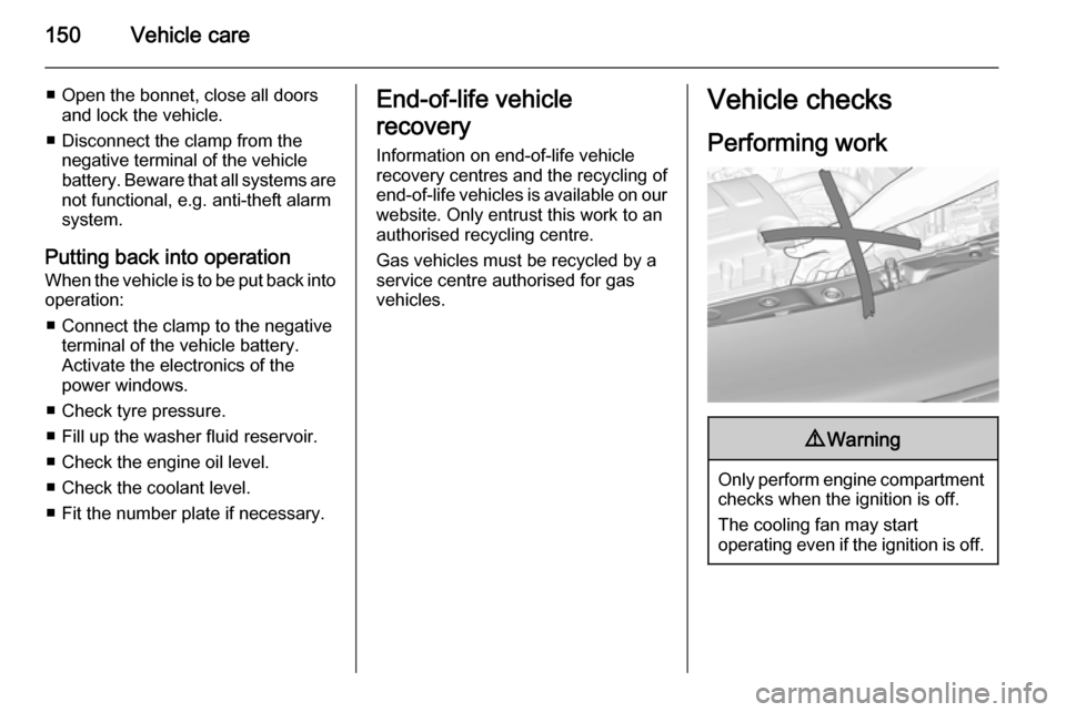
Performing work9 Warning
Only perform engine compartment
checks when the ignition is off.
The cooling fan may start
operating even if the ignition is off.
Page 159 of 217
Vehicle care157
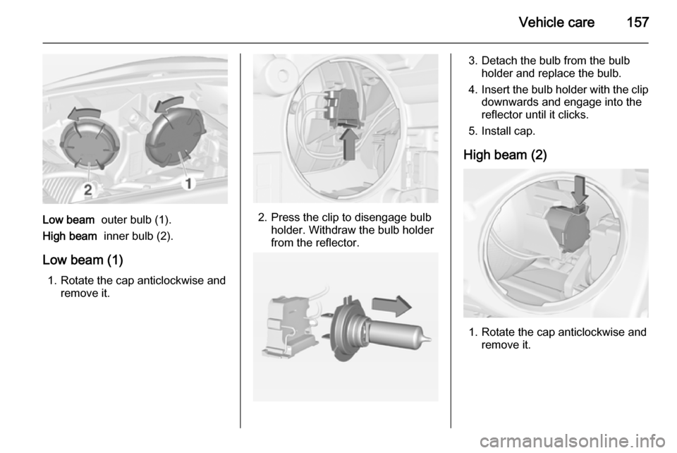
Low beam outer bulb (1).
High beam inner bulb (2).
Low beam (1) 1. Rotate the cap anticlockwise and remove it.2. Press the clip to disengage bulbholder. Withdraw the bulb holder
from the reflector.
3. Detach the bulb from the bulb holder and replace the bulb.
4. Insert the bulb holder with the clip
downwards and engage into the
reflector until it clicks.
5. Install cap.
High beam (2)
1. Rotate the cap anticlockwise and remove it.
Page 160 of 217
158Vehicle care
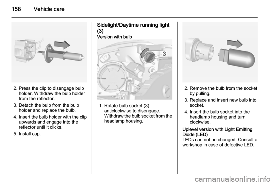
2. Press the clip to disengage bulbholder. Withdraw the bulb holder
from the reflector.
3. Detach the bulb from the bulb holder and replace the bulb.
4. Insert the bulb holder with the clip
upwards and engage into the
reflector until it clicks.
5. Install cap.
Sidelight/Daytime running light
(3)Version with bulb
1. Rotate bulb socket (3) anticlockwise to disengage.
Withdraw the bulb socket from the
headlamp housing.2. Remove the bulb from the socket by pulling.
3. Replace and insert new bulb into socket.
4. Insert the bulb socket into the headlamp housing and turn
clockwise.
Uplevel version with Light Emitting
Diode (LED)
LEDs can not be changed. Consult a
workshop in case of defective LED.
Page 161 of 217
Vehicle care159Front turn signal lights
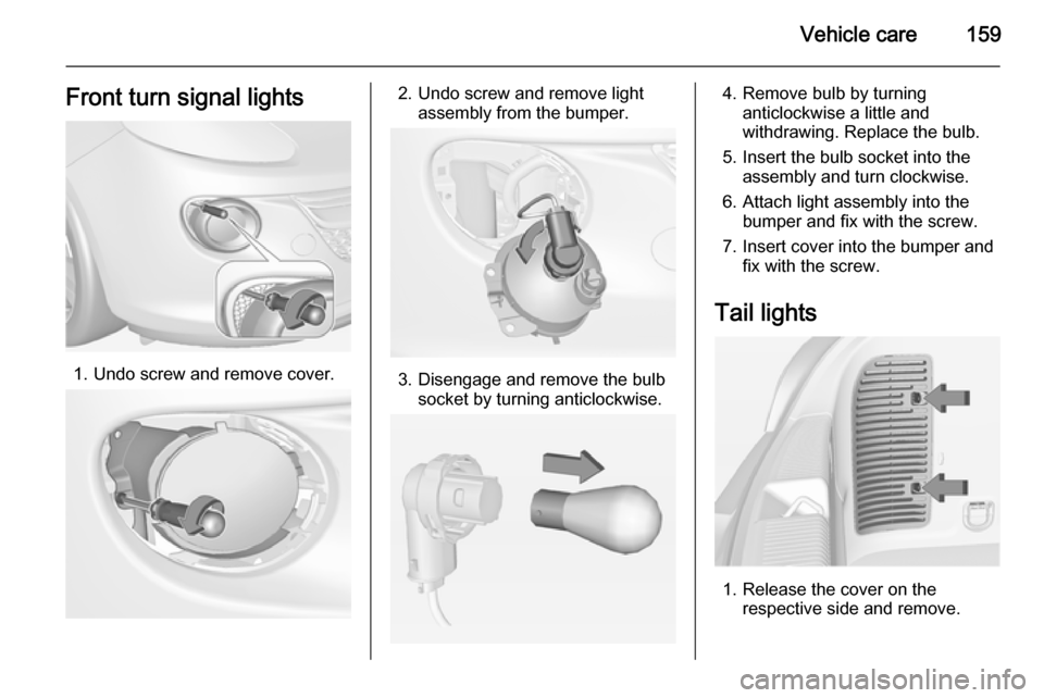
1. Undo screw and remove cover.
2. Undo screw and remove lightassembly from the bumper.
3. Disengage and remove the bulbsocket by turning anticlockwise.
4. Remove bulb by turninganticlockwise a little and
withdrawing. Replace the bulb.
5. Insert the bulb socket into the assembly and turn clockwise.
6. Attach light assembly into the bumper and fix with the screw.
7. Insert cover into the bumper and fix with the screw.
Tail lights
1. Release the cover on the respective side and remove.
Page 162 of 217
160Vehicle care
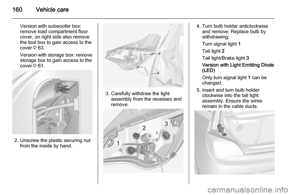
Version with subwoofer box:
remove load compartment floor
cover, on right side also remove
the tool box to gain access to the
cover 3 63.
Version with storage box: remove
storage box to gain access to the
cover 3 61.
2. Unscrew the plastic securing nut
from the inside by hand.
3. Carefully withdraw the lightassembly from the recesses and
remove.
4. Turn bulb holder anticlockwise and remove. Replace bulb by
withdrawing:
Turn signal light 1
Tail light 2
Tail light/Brake light 3
Version with Light Emitting Diode (LED)
Only turn signal light 1 can be
changed.
5. Insert and turn bulb holder clockwise into the tail light
assembly. Ensure the wires
remain in the cable ducts.
Page 163 of 217

Vehicle care161
Fit light assembly with theretaining pins into the recesses of
the vehicle body and tighten the
securing nut from inside the load compartment. Pull the circular
gasket over the recess in the lamp housing.
Close cover and engage.
Reversing light/rear fog light Reversing light is located on the right
side of the bumper, and the rear fog
light is located on the left side of the
bumper for left-hand drive vehicles,
and vice versa for right hand drive
models.
The description of bulb replacement
is the same for both.
1. Undo screw and remove cover.
2. Undo screw and remove light assembly from the bumper.
3. Disengage and remove the bulbsocket by turning anticlockwise.
Page 164 of 217

162Vehicle care
4. Remove bulb by turninganticlockwise slightly and
withdrawing. Replace the bulb.
5. Insert the bulb socket into the assembly and turn clockwise.
6. Replace light assembly in the bumper and fix with the screw.
7. Insert cover into the bumper and fix with the screw.
Side turn signal lights
To replace bulb, remove lamp
housing:1. On left vehicle side, slide lamp to the front and remove it out of the
wing with the rear end.
On right vehicle side, slide lamp to
the rear and remove it out of the wing with the front end.
2. Turn bulb holder anticlockwise and remove from housing.
3. Pull bulb from bulb holder andreplace it.
4. Insert bulb holder and turn clockwise.
5. On left vehicle side: insert front end into fender, slide forward and
insert rear end.
On right vehicle side: insert rear
end into fender, slide rearward
and insert front end.
Page 165 of 217

Vehicle care163Number plate light
1.Insert screwdriver in recess of the
cover, press to the side and
release spring.
2. Remove lamp downwards, taking care not to pull on the cable.
3. Remove bulb holder from lamp housing by turning anticlockwise.
4. Pull bulb from bulb holder andreplace it.
5. Insert bulb holder into lamp housing and turn clockwise.
6. Insert lamp into bumper and let engage.
Interior lights Courtesy light, reading lights
Have bulbs replaced by a workshop.
Load compartment light Have bulbs replaced by a workshop.
Dome light, ambient light,starlight panel
Have bulbs replaced by a workshop.
Instrument panel
illumination
Have bulbs replaced by a workshop.
Page 177 of 217

Vehicle care175Changing tyre and wheel
size If tyres of a different size than those
fitted at the factory are used, it may be
necessary to reprogramme the
speedometer as well as the nominal
tyre pressure and make other vehicle modifications.
After converting to a different tyre
size, have the label with tyre
pressures replaced.9 Warning
Use of unsuitable tyres or wheels
may lead to accidents and will
invalidate the vehicle type
approval.
Wheel covers
Wheel covers and tyres that are
factory approved for the respective
vehicle and comply with all of the
relevant wheel and tyre combination requirements must be used.
If the wheel covers and tyres used are
not factory approved, the tyres must
not have a rim protection ridge.
Wheel covers must not impair brake
cooling.9 Warning
Use of unsuitable tyres or wheel
covers could lead to sudden
pressure loss and thereby
accidents.
Tyre chains
Tyre chains are only permitted on the
front wheels.
Always use fine mesh chains that add no more than 10 mm to the tyre tread
and the inboard sides (including chain lock).9 Warning
Damage may lead to tyre blowout.
Tyre chains are only permitted on
tyres of size 175/70 R 14,
185/60 R 15, 185/65 R 15 and 195/55 R 16.
Tyre chains are not permitted on tyres of size 215/45 R 17 and 225/35 R 18 .
The use of tyre chains is not permitted
on the temporary spare wheel.
Tyre repair kit
Minor damage to the tyre tread can be
repaired with the tyre repair kit.
Do not remove foreign bodies from
the tyres.
Page 184 of 217
182Vehicle care
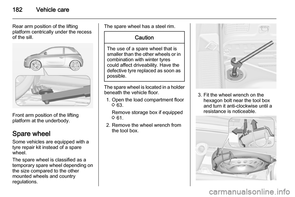
Rear arm position of the lifting
platform centrically under the recess
of the sill.
Front arm position of the lifting
platform at the underbody.
Spare wheel Some vehicles are equipped with a
tyre repair kit instead of a spare
wheel.
The spare wheel is classified as a
temporary spare wheel depending on the size compared to the other
mounted wheels and country
regulations.
The spare wheel has a steel rim.Caution
The use of a spare wheel that is smaller than the other wheels or in combination with winter tyres
could affect driveability. Have the defective tyre replaced as soon as
possible.
The spare wheel is located in a holder
beneath the vehicle floor.
1. Open the load compartment floor 3 63.
Remove storage box if equipped
3 61.
2. Remove the wheel wrench from the tool box.
3. Fit the wheel wrench on the hexagon bolt near the tool box
and turn it anti-clockwise until a
resistance is noticeable.