engine VAUXHALL ADAM 2014 Workshop Manual
[x] Cancel search | Manufacturer: VAUXHALL, Model Year: 2014, Model line: ADAM, Model: VAUXHALL ADAM 2014Pages: 217, PDF Size: 6.68 MB
Page 166 of 217
164Vehicle careElectrical systemFuses
Data on the replacement fuse must
match the data on the defective fuse.
There are two fuse boxes in the
vehicle:
■ in the front left of the engine compartment,
■ in left-hand drive vehicles behind the light switch, or, in right-hand
drive vehicles, behind the
glovebox.
Before replacing a fuse, turn off the
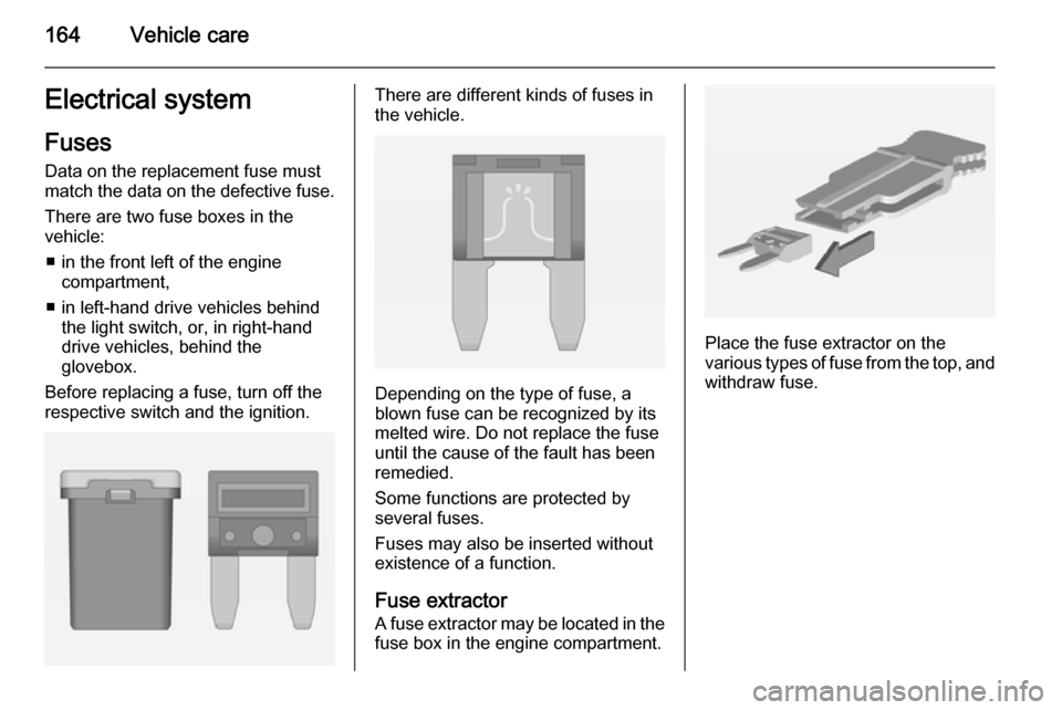
respective switch and the ignition.There are different kinds of fuses in
the vehicle.
Depending on the type of fuse, a
blown fuse can be recognized by its
melted wire. Do not replace the fuse until the cause of the fault has been
remedied.
Some functions are protected by
several fuses.
Fuses may also be inserted without existence of a function.
Fuse extractor A fuse extractor may be located in the fuse box in the engine compartment.
Place the fuse extractor on the
various types of fuse from the top, and
withdraw fuse.
Page 167 of 217
Vehicle care165Engine compartment fuse
box
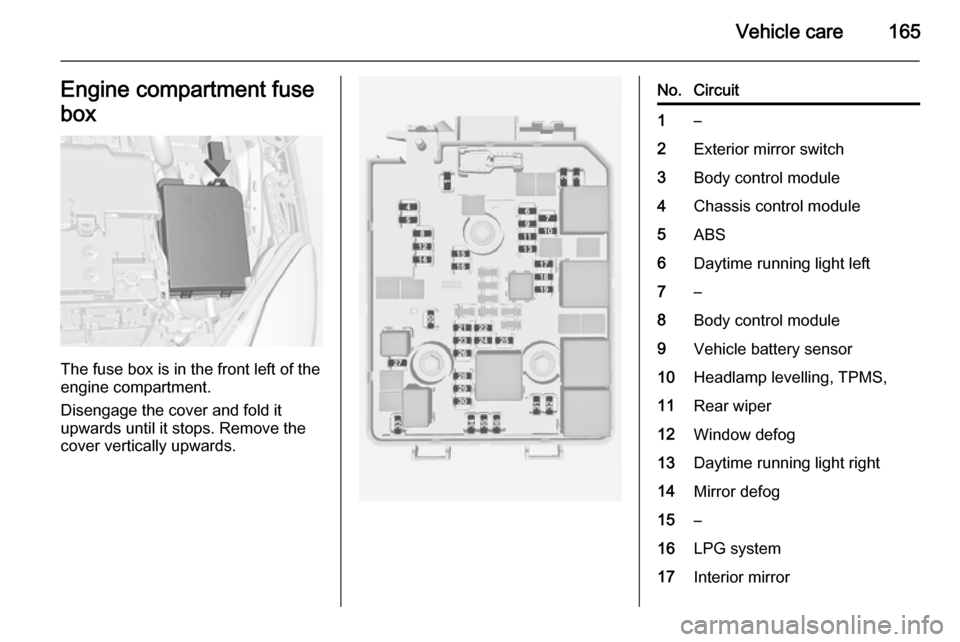
The fuse box is in the front left of the
engine compartment.
Disengage the cover and fold it
upwards until it stops. Remove the
cover vertically upwards.
No.Circuit1–2Exterior mirror switch3Body control module4Chassis control module5ABS6Daytime running light left7–8Body control module9Vehicle battery sensor10Headlamp levelling, TPMS,11Rear wiper12Window defog13Daytime running light right14Mirror defog15–16LPG system17Interior mirror
Page 168 of 217
166Vehicle care
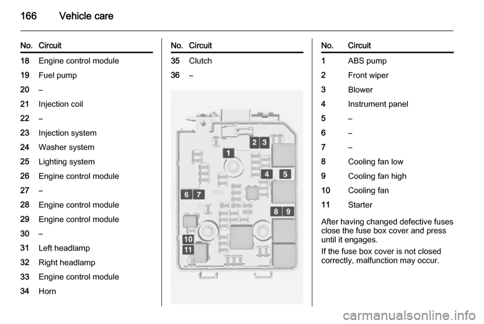
No.Circuit18Engine control module19Fuel pump20–21Injection coil22–23Injection system24Washer system25Lighting system26Engine control module27–28Engine control module29Engine control module30–31Left headlamp32Right headlamp33Engine control module34HornNo.Circuit35Clutch36–No.Circuit1ABS pump2Front wiper3Blower4Instrument panel5–6–7–8Cooling fan low9Cooling fan high10Cooling fan11Starter
After having changed defective fuses
close the fuse box cover and press
until it engages.
If the fuse box cover is not closed
correctly, malfunction may occur.
Page 171 of 217

Vehicle care169Vehicle tools
Tools Vehicles with tyre repair kit
Some tools and the towing eye are
located together with the tyre repair
kit in a tool box in the load
compartment below the floor cover.
On version with storage box, remove
box first 3 61.
On versions with rear carrier system
or liquid gas engine, the tools are
located together with the towing eye
and tyre repair kit in a suitcase, fixed
with a strap at the left sidewall in the
load compartment.On version with storage box, the
suitcase with the tools, the towing eye
and the tyre repair kit is located in a
chamber of the box in the load
compartment 3 61.
Page 173 of 217
Vehicle care171Tyre designationsE.g. 195/55 R 16 95 H195=Tyre width, mm55=Cross-section ratio (tyre
height to tyre width), %R=Belt type: RadialRF=Type: RunFlat16=Wheel diameter, inches95=Load index e.g. 95 is
equivalent to 690 kgH=Speed code letter
Speed code letter:
Q=up to 100 mphS=up to 112 mphT=up to 118 mphH=up to 130 mphV=up to 150 mphW=up to 168 mph
Tyre pressure
Check the pressure of cold tyres at
least every 14 days and before any
long journey. Do not forget the spare
wheel. This also applies to vehicles
with tyre pressure monitoring system.
Unscrew the valve cap.
Tyre pressure 3 206.
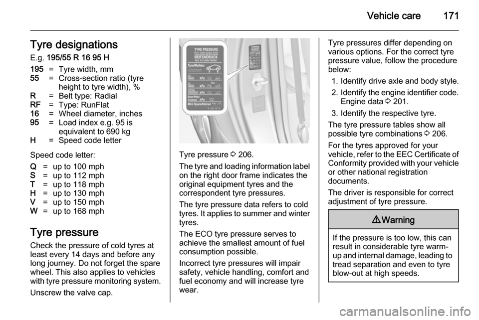
The tyre and loading information label on the right door frame indicates the
original equipment tyres and the
correspondent tyre pressures.
The tyre pressure data refers to cold
tyres. It applies to summer and winter tyres.
The ECO tyre pressure serves to
achieve the smallest amount of fuel
consumption possible.
Incorrect tyre pressures will impair
safety, vehicle handling, comfort and fuel economy and will increase tyre
wear.
Tyre pressures differ depending on
various options. For the correct tyre
pressure value, follow the procedure
below:
1. Identify drive axle and body style.
2. Identify the engine identifier code.
Engine data 3 201.
3. Identify the respective tyre.
The tyre pressure tables show all possible tyre combinations 3 206.
For the tyres approved for your
vehicle, refer to the EEC Certificate of Conformity provided with your vehicle
or other national registration
documents.
The driver is responsible for correct
adjustment of tyre pressure.9 Warning
If the pressure is too low, this can
result in considerable tyre warm-
up and internal damage, leading to tread separation and even to tyre
blow-out at high speeds.
Page 178 of 217

176Vehicle care
Tyre damage exceeding 4 mm or thatis at tyre's sidewall cannot be repairedwith the tyre repair kit.9 Warning
Do not drive faster than 50 mph.
Do not use for a lengthy period.
Steering and handling may be
affected.
If you have a flat tyre:
Apply the parking brake and engage
first gear.
The tyre repair kit is in the tool box
under the floor cover in the load
compartment.
On versions with rear carrier system
or liquid gas engine, tyre repair kit is
located in a suitcase and fixed with a strap at the left sidewall in the load
compartment.
On versions with storage box in the
load compartment the suitcase with
the tyre repair kit is located in a
chamber of the box 3 61.
Page 180 of 217
178Vehicle care
9. Connect the compressor plug tothe power outlet or cigarette
lighter socket.
To avoid discharging the battery,
we recommend running the
engine.
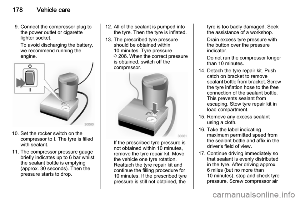
10. Set the rocker switch on the compressor to I. The tyre is filled
with sealant.
11. The compressor pressure gauge briefly indicates up to 6 bar whilstthe sealant bottle is emptying
(approx. 30 seconds). Then the
pressure starts to drop.
12. All of the sealant is pumped into the tyre. Then the tyre is inflated.
13. The prescribed tyre pressure should be obtained within
10 minutes. Tyre pressure
3 206 . When the correct pressure
is obtained, switch off the
compressor.
If the prescribed tyre pressure is
not obtained within 10 minutes,
remove the tyre repair kit. Move
the vehicle one tyre rotation.
Reattach the tyre repair kit and
continue the filling procedure for
10 minutes. If the prescribed tyre
pressure is still not obtained, the
tyre is too badly damaged. Seek
the assistance of a workshop.
Drain excess tyre pressure with
the button over the pressure indicator.
Do not run the compressor longer
than 10 minutes.
14. Detach the tyre repair kit. Push catch on bracket to remove
sealant bottle from bracket. Screw the tyre inflation hose to the freeconnection of the sealant bottle.
This prevents sealant from
escaping. Stow tyre repair kit in
load compartment.
15. Remove any excess sealant using a cloth.
16. Take the label indicating maximum permitted speed from
the sealant bottle and affix in the
driver's field of view.
17. Continue driving immediately so that sealant is evenly distributedin the tyre. After driving approx.
6 miles (but no more than
10 minutes), stop and check tyre
pressure. Screw compressor air
Page 189 of 217
Vehicle care187
■ Never expose the battery to nakedflames or sparks.
■ A discharged vehicle battery can already freeze at a temperature of
0 °C. Defrost the frozen battery
before connecting jump leads.
■ Wear eye protection and protective
clothing when handling a battery.
■ Use a booster battery with the same voltage (12 Volts). Its
capacity (Ah) must not be much less than that of the discharged
battery.
■ Use jump leads with insulated terminals and a cross section of at
least 16 mm 2
(25 mm 2
for diesel
engines).
■ Do not disconnect the discharged vehicle battery from the vehicle.
■ Switch off all unnecessary electrical
consumers.
■ Do not lean over the battery during jump starting.
■ Do not allow the terminals of one lead to touch those of the other
lead.■ The vehicles must not come into contact with each other during thejump starting process.
■ Apply the parking brake, transmission in neutral.
■ Open the positive terminal protection caps of both vehicle
batteries.
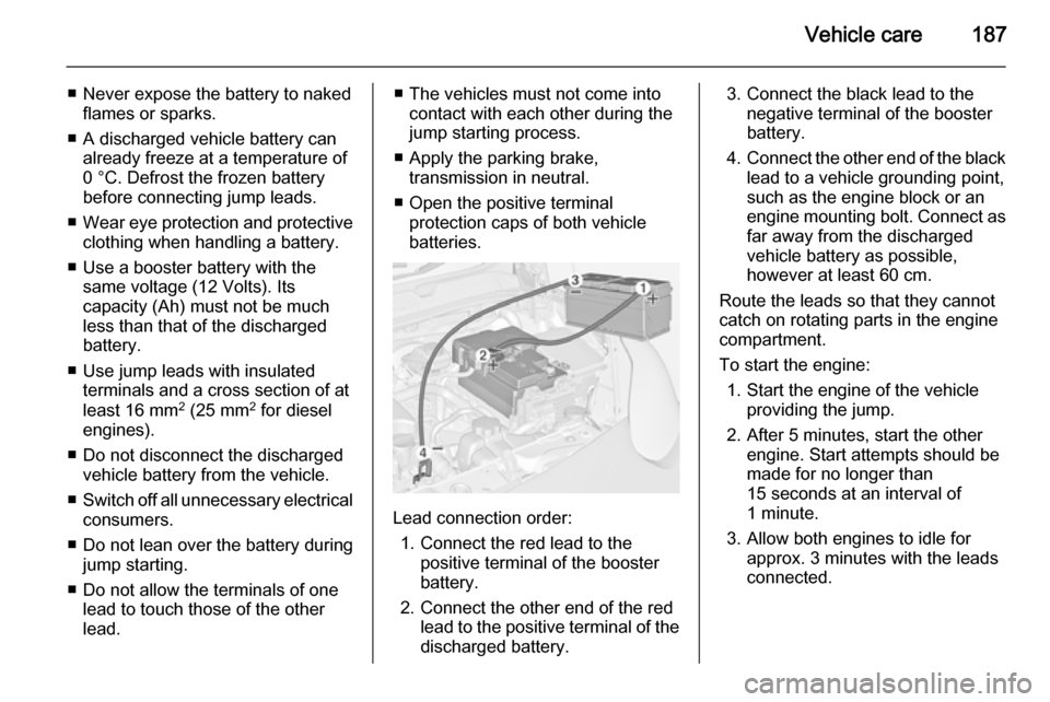
Lead connection order:
1. Connect the red lead to the positive terminal of the booster
battery.
2. Connect the other end of the red lead to the positive terminal of the
discharged battery.
3. Connect the black lead to the negative terminal of the booster
battery.
4. Connect the other end of the black
lead to a vehicle grounding point,
such as the engine block or an
engine mounting bolt. Connect as far away from the discharged
vehicle battery as possible,
however at least 60 cm.
Route the leads so that they cannot
catch on rotating parts in the engine
compartment.
To start the engine: 1. Start the engine of the vehicle providing the jump.
2. After 5 minutes, start the other engine. Start attempts should be
made for no longer than
15 seconds at an interval of
1 minute.
3. Allow both engines to idle for approx. 3 minutes with the leads
connected.
Page 191 of 217

Vehicle care189Caution
Drive slowly. Do not drive jerkily.
Excessive tractive force can
damage the vehicle.
When the engine is not running,
considerably more force is needed to
brake and steer.
To prevent the entry of exhaust gases from the towing vehicle, switch on the
air recirculation and close the
windows.
Seek the assistance of a workshop.
After towing, unscrew the towing eye.
Insert cap and engage in the bumper.
Towing another vehicle
Insert a screwdriver in the slot at the
lower bend of the cap. Disengage the cap by carefully moving the
screwdriver downwards.
The towing eye is stowed with the
vehicle tools 3 169.
Screw in the towing eye as far as it will
go until it stops in a horizontal
position.
The lashing eye at the rear
underneath the vehicle must never be used as a towing eye.
Attach a tow rope – or even better a
tow bar – to the towing eye.
The towing eye must only be used for
towing and not for recovering a
vehicle.
Page 192 of 217
190Vehicle careCaution
Drive slowly. Do not drive jerkily.
Excessive tractive force can
damage the vehicle.
After towing, unscrew the towing eye.
Insert cap and engage in the bumper.
Appearance care
Exterior care Locks
The locks are lubricated at the factory using a high quality lock cylinder
grease. Use de-icing agent only when absolutely necessary, as this has a
degreasing effect and impairs lock
function. After using de-icing agent,
have the locks regreased by a
workshop.
Washing The paintwork of your vehicle is
exposed to environmental influences.
Wash and wax your vehicle regularly.
When using automatic vehicle
washes, select a programme that
includes waxing.
Bird droppings, dead insects, resin,
pollen and the like should be cleaned
off immediately, as they contain
aggressive constituents which can
cause paint damage.If using a vehicle wash, comply with
the vehicle wash manufacturer's instructions. The windscreen wiperand rear window wiper must be
switched off. Remove antenna and
external accessories such as roof
racks etc.
If you wash your vehicle by hand,
make sure that the insides of the
wheel housings are also thoroughly
rinsed out.
Clean edges and folds on opened
doors and the bonnet as well as the
areas they cover.Caution
Always use a cleaning agent with
a pH value of 4 to 9.
Do not use cleaning agents on hot surfaces.
Have the door hinges of all doors
greased by a workshop.
Do not clean the engine compartment with a steam-jet or high-pressure jet
cleaner.