service VAUXHALL ADAM 2015 Owner's Manual
[x] Cancel search | Manufacturer: VAUXHALL, Model Year: 2015, Model line: ADAM, Model: VAUXHALL ADAM 2015Pages: 225, PDF Size: 6.81 MB
Page 3 of 225

Introduction.................................... 2
In brief ............................................ 6
Keys, doors and windows ............19
Seats, restraints ........................... 32
Storage ........................................ 52
Instruments and controls .............71
Lighting ...................................... 103
Climate control ........................... 111
Driving and operating .................121
Vehicle care ............................... 152
Service and maintenance ..........201
Technical data ........................... 204
Customer information ................215
Index .......................................... 218Contents
Page 5 of 225

Introduction3Vehicle specific data
Please enter your vehicle's data on
the previous page to keep it easily
accessible. This information is
available in the sections "Service and maintenance" and "Technical data"
as well as on the identification plate.
Introduction
Your vehicle is a designed
combination of advanced technology, safety, environmental friendliness
and economy.
This Owner's Manual provides you
with all the necessary information to
enable you to drive your vehicle
safely and efficiently.
Make sure your passengers are
aware of the possible risk of accident
and injury which may result from
improper use of the vehicle.
You must always comply with the
specific laws and regulations of the
country that you are in. These laws
may differ from the information in this Owner's Manual.When this Owner's Manual refers to aworkshop visit, we recommend your
Vauxhall Authorised Repairer.
For gas vehicles, we recommend a
Vauxhall Authorised Repairer
licensed to service gas vehicles.
All Vauxhall Authorised Repairers
provide first-class service at
reasonable prices. Experienced
mechanics trained by Vauxhall work
according to specific Vauxhall
instructions.
The customer literature pack should
always be kept ready to hand in the
vehicle.
Using this manual ■ This manual describes all options and features available for this
model. Certain descriptions,
including those for display and
menu functions, may not apply to
your vehicle due to model variant,
country specifications, special
equipment or accessories.
■ The "In brief" section will give you an initial overview.■ The table of contents at thebeginning of this manual and withineach section shows where the
information is located.
■ The index will enable you to search
for specific information.
■ This Owner's Manual depicts left- hand drive vehicles. Operation is
similar for right-hand drive vehicles.
■ The Owner's Manual uses the factory engine designations. The
corresponding sales designations
can be found in the section
"Technical data".
■ Directional data, e.g. left or right, or
front or back, always relate to the
direction of travel.
■ The vehicle display screens may not support your specific language.
■ Display messages and interior labelling are written in bold letters.
Page 83 of 225

Instruments and controls81
left area=engine operating
temperature not
yet reachedcentral area=normal operating
temperatureright area=temperature too
highCaution
If engine coolant temperature is
too high, stop vehicle, switch off
engine. Danger to engine. Check
coolant level.
Service display
The engine oil life system lets you
know when to change the engine oil
and filter. Based on driving
conditions, the interval at which an
engine oil and filter change will be
indicated can vary considerably.
The remaining engine oil life duration
is displayed in percent by the control
indicator I on the Midlevel-Display.
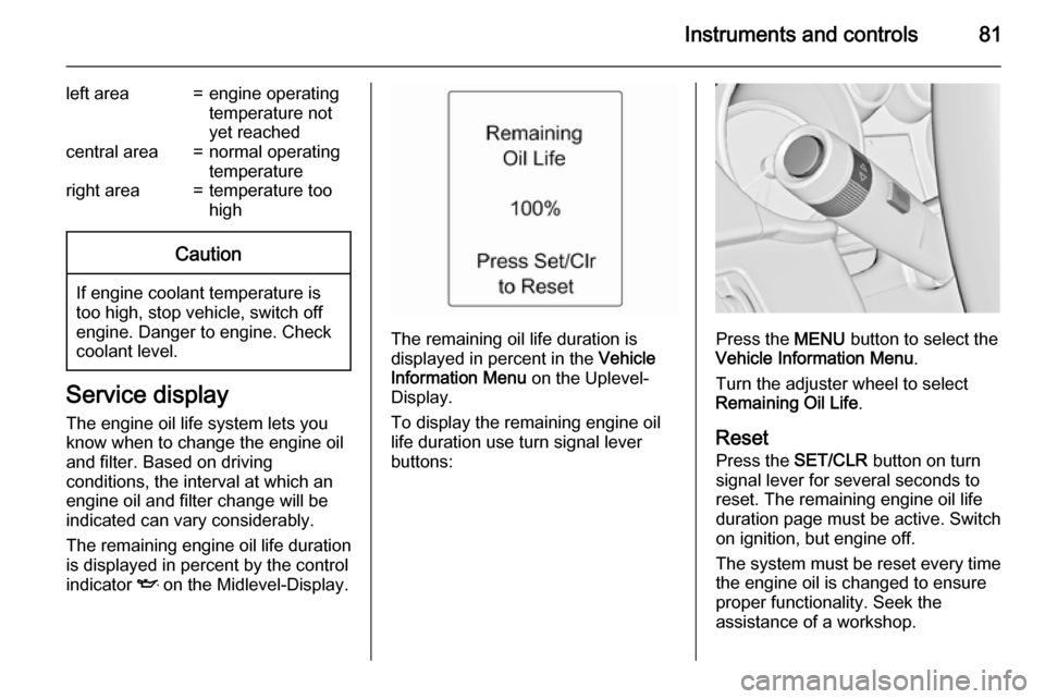
The remaining oil life duration is
displayed in percent in the Vehicle
Information Menu on the Uplevel-
Display.
To display the remaining engine oil
life duration use turn signal lever
buttons:Press the MENU button to select the
Vehicle Information Menu .
Turn the adjuster wheel to select Remaining Oil Life .
Reset Press the SET/CLR button on turn
signal lever for several seconds to
reset. The remaining engine oil life
duration page must be active. Switch
on ignition, but engine off.
The system must be reset every time
the engine oil is changed to ensure
proper functionality. Seek the
assistance of a workshop.
Page 84 of 225

82Instruments and controls
Next service
When the system has calculated that
engine oil life has diminished, a
warning message appears in the
Driver Information Centre. Have
engine oil and filter changed by a
workshop within one week or
300 miles (whichever occurs first).
Driver Information Centre 3 89.
Service information 3 201.
Control indicators The control indicators described are
not present in all vehicles. The
description applies to all instrument
versions. Depending on the
equipment, the position of the control
indicators may vary. When the
ignition is switched on, most control
indicators will illuminate briefly as a functionality test.
The control indicator colours mean:red=danger, important reminderyellow=warning, information, faultgreen=confirmation of activationblue=confirmation of activationwhite=confirmation of activation
Page 88 of 225

86Instruments and controls
Flashes when the engine isrunning
Fault that could lead to catalytic
converter damage. Ease up on the
accelerator until the flashing stops.
Seek the assistance of a workshop
immediately.
Service vehicle soon g illuminates yellow.
Additionally a warning message is
displayed in the Driver Information
Centre.
The vehicle needs a service.
Seek the assistance of a workshop. Vehicle messages 3 96.
Brake and clutch system R illuminates red.
The brake and clutch fluid level is too low 3 156.9 Warning
Stop. Do not continue your
journey. Consult a workshop.
Illuminates after the ignition is
switched on if the manual parking
brake is applied 3 128.
Operate pedal - illuminates or flashes yellow.
Illuminates
Clutch pedal needs to be depressed
to start the engine in Autostop mode.
Stop-start system 3 123.
Flashes
Clutch pedal needs to be depressed
for a main start of the engine 3 16,
3 122.
On some versions, the operate pedal message is indicated in the Driver
Information Display 3 96.
Antilock brake system
(ABS) u illuminates yellow.
Illuminates for a few seconds after the
ignition is switched on. The system is ready for operation when the control
indicator extinguishes.
If the control indicator does not go out after a few seconds, or if it illuminates while driving, there is a fault in the
ABS. The brake system remains
operational but without ABS
regulation.
Antilock brake system 3 127.
Upshift
[ illuminates green as control
indicator or is shown as a symbol in
the Driver Information Centre with
Uplevel-Display, when upshifting is
recommended for fuel saving
reasons.
Eco information menu
The gear shift indication is popped-up
as a full page in the Driver Information Centre.
Page 99 of 225

Instruments and controls97
No.Vehicle message27right front turn signal failure28right rear turn signal failure35replace battery in radio remote
control48clean side blind spot alert
system53tighten gas cap56tyre pressure imbalance on
front axle57tyre pressure imbalance on rear
axle58winter tyres detection59open and then close driver
window60open and then close front
passenger window66service theft alarm system67service steering wheel lock68service power steeringNo.Vehicle message75service air conditioning76service side blind spot alert
system79top up engine oil82change engine oil soon84engine power reduced89service vehicle soon95service airbag128bonnet open134park assist fault, clean bumper136service parking assist174low vehicle battery258park assist offVehicle messages on the
Uplevel-Display
The vehicle messages are displayed
as text. Follow the instructions given
in the messages.
The system displays messages
regarding the following topics:
■ fluid levels
■ anti-theft alarm system
■ brakes
■ ride control systems
■ cruise control, speed limiter
■ parking assist systems
Page 122 of 225

120Climate controlAir conditioning regular
operation In order to ensure continuously
efficient performance, cooling must
be operated for a few minutes once a
month, irrespective of the weather
and time of year. Operation with
cooling is not possible when the
outside temperature is too low.
Service
For optimal cooling performance, it is recommended to annually check the
climate control system, starting
three years after initial vehicle
registration, including:
■ functionality and pressure test
■ heating functionality
■ leakage check
■ check of drive belts
■ cleaning of condenser and evaporator drainage
■ performance check
Page 124 of 225

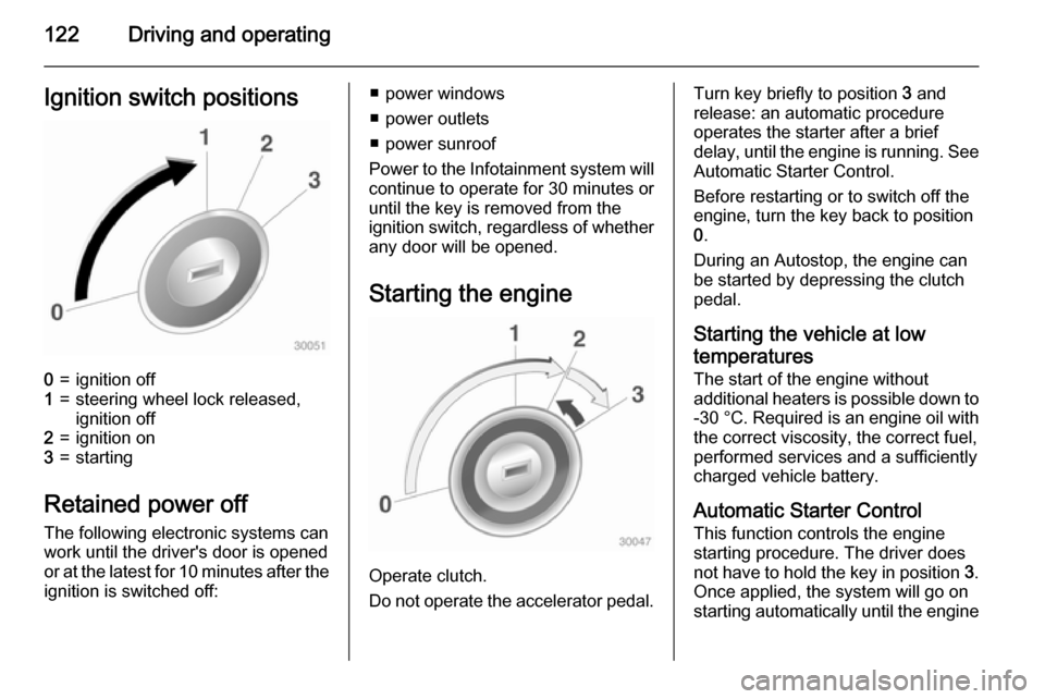
122Driving and operatingIgnition switch positions0=ignition off1=steering wheel lock released,
ignition off2=ignition on3=starting
Retained power off
The following electronic systems can
work until the driver's door is opened
or at the latest for 10 minutes after the
ignition is switched off:
■ power windows
■ power outlets
■ power sunroof
Power to the Infotainment system will continue to operate for 30 minutes or
until the key is removed from the
ignition switch, regardless of whether
any door will be opened.
Starting the engine
Operate clutch.
Do not operate the accelerator pedal.
Turn key briefly to position 3 and
release: an automatic procedure operates the starter after a brief
delay, until the engine is running. See
Automatic Starter Control.
Before restarting or to switch off the
engine, turn the key back to position
0 .
During an Autostop, the engine can
be started by depressing the clutch
pedal.
Starting the vehicle at low
temperatures
The start of the engine without
additional heaters is possible down to -30 °C . Required is an engine oil with
the correct viscosity, the correct fuel,
performed services and a sufficiently
charged vehicle battery.
Automatic Starter Control
This function controls the engine
starting procedure. The driver does
not have to hold the key in position 3.
Once applied, the system will go on starting automatically until the engine
Page 155 of 225

Vehicle care153
■ Open the bonnet, close all doorsand lock the vehicle.
■ Disconnect the clamp from the negative terminal of the vehicle
battery. Beware that all systems are
not functional, e.g. anti-theft alarm
system.
Putting back into operation
When the vehicle is to be put back into
operation:
■ Connect the clamp to the negative terminal of the vehicle battery.
Activate the electronics of the
power windows.
■ Check tyre pressure.
■ Fill up the washer fluid reservoir.
■ Check the engine oil level.
■ Check the coolant level.
■ Fit the number plate if necessary.End-of-life vehicle
recovery
Information on end-of-life vehicle
recovery centres and the recycling of
end-of-life vehicles is available on our website. Only entrust this work to an
authorised recycling centre.
Gas vehicles must be recycled by a
service centre authorised for gas
vehicles.Vehicle checks
Performing work9 Warning
Only perform engine compartment
checks when the ignition is off.
The cooling fan may start
operating even if the ignition is off.
Page 180 of 225

178Vehicle care
The use of commercially-availableliquid tyre repair kits can impair the
function of the system. Factory-
approved repair kits can be used.
External high-power radio equipment
could disrupt the tyre pressure
monitoring system.
Each time the tyres are replaced, tyre pressure monitoring system sensors
must be dismounted and serviced.
For the screwed sensor; replace
valve core and sealing ring. For the
clipped sensor; replace complete
valve stem.
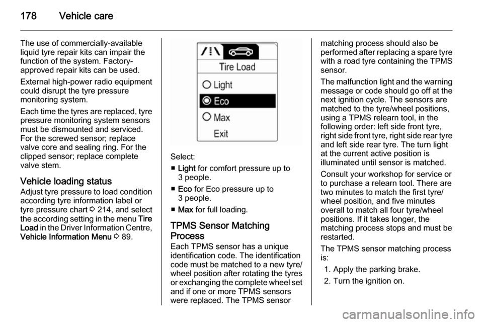
Vehicle loading status Adjust tyre pressure to load condition according tyre information label or
tyre pressure chart 3 214, and select
the according setting in the menu Tire
Load in the Driver Information Centre,
Vehicle Information Menu 3 89.
Select:
■ Light for comfort pressure up to
3 people.
■ Eco for Eco pressure up to
3 people.
■ Max for full loading.
TPMS Sensor Matching
Process
Each TPMS sensor has a unique
identification code. The identification
code must be matched to a new tyre/
wheel position after rotating the tyres
or exchanging the complete wheel set
and if one or more TPMS sensors
were replaced. The TPMS sensor
matching process should also be
performed after replacing a spare tyre with a road tyre containing the TPMS
sensor.
The malfunction light and the warning
message or code should go off at the
next ignition cycle. The sensors are
matched to the tyre/wheel positions,
using a TPMS relearn tool, in the
following order: left side front tyre,
right side front tyre, right side rear tyre and left side rear tyre. The turn light
at the current active position is
illuminated until sensor is matched.
Consult your workshop for service or
to purchase a relearn tool. There are
two minutes to match the first tyre/
wheel position, and five minutes
overall to match all four tyre/wheel
positions. If it takes longer, the
matching process stops and must be
restarted.
The TPMS sensor matching process is:
1. Apply the parking brake.
2. Turn the ignition on.