tow VAUXHALL ADAM 2016.5 Owner's Guide
[x] Cancel search | Manufacturer: VAUXHALL, Model Year: 2016.5, Model line: ADAM, Model: VAUXHALL ADAM 2016.5Pages: 239, PDF Size: 7.2 MB
Page 195 of 239
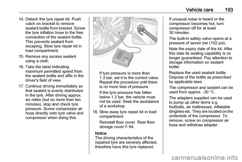
Vehicle care19314. Detach the tyre repair kit. Pushcatch on bracket to remove
sealant bottle from bracket. Screw the tyre inflation hose to the free
connection of the sealant bottle.
This prevents sealant from
escaping. Stow tyre repair kit in
load compartment.
15. Remove any excess sealant using a cloth.
16. Take the label indicating maximum permitted speed from
the sealant bottle and affix in the
driver's field of view.
17. Continue driving immediately so that sealant is evenly distributedin the tyre. After driving approx.
six miles (but no more than ten
minutes), stop and check tyre
pressure. Screw compressor air
hose directly onto tyre valve and
compressor when doing this.
If tyre pressure is more than 1.3 bar , set it to the correct value.
Repeat the procedure until there
is no more loss of pressure.
If the tyre pressure has fallen
below 1.3 bar, the vehicle must
not be used. Seek the assistance
of a workshop.
18. Stow away tyre repair kit in load compartment.
Reinstall floor cover. Rear floor
storage cover 3 64.
Notice
The driving characteristics of the
repaired tyre are severely affected, therefore have this tyre replaced.
If unusual noise is heard or the
compressor becomes hot, turn
compressor off for at least
30 minutes.
The built-in safety valve opens at a
pressure of seven bar (102 psi).
Note the expiry date of the kit. After
this date its sealing capability is no
longer guaranteed. Pay attention to
storage information on sealant
bottle.
Replace the used sealant bottle. Dispose of the bottle as prescribed
by applicable laws.
The compressor and sealant can be used from approx. -30 °C.
The adapters supplied can be used
to pump up other items e.g.
footballs, air mattresses, inflatable
dinghies etc. They are located on the
underside of the compressor. To
remove, screw on compressor air hose and withdraw adapter.
Page 198 of 239
196Vehicle care
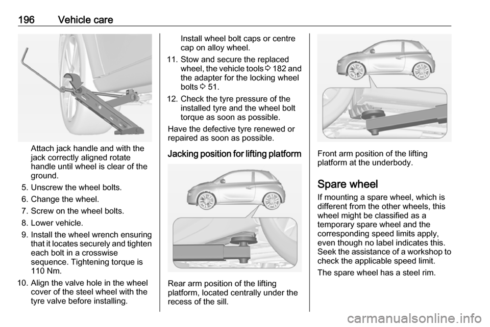
Attach jack handle and with the
jack correctly aligned rotate handle until wheel is clear of theground.
5. Unscrew the wheel bolts.
6. Change the wheel.
7. Screw on the wheel bolts.
8. Lower vehicle.
9. Install the wheel wrench ensuring that it locates securely and tighten
each bolt in a crosswise
sequence. Tightening torque is
110 Nm.
10. Align the valve hole in the wheel cover of the steel wheel with the
tyre valve before installing.
Install wheel bolt caps or centre
cap on alloy wheel.
11. Stow and secure the replaced wheel, the vehicle tools 3 182 and
the adapter for the locking wheel
bolts 3 51.
12. Check the tyre pressure of the installed tyre and the wheel bolt
torque as soon as possible.
Have the defective tyre renewed or
repaired as soon as possible.
Jacking position for lifting platform
Rear arm position of the lifting
platform, located centrally under the
recess of the sill.
Front arm position of the lifting platform at the underbody.
Spare wheel If mounting a spare wheel, which is
different from the other wheels, this
wheel might be classified as a
temporary spare wheel and the
corresponding speed limits apply,
even though no label indicates this.
Seek the assistance of a workshop to
check the applicable speed limit.
The spare wheel has a steel rim.
Page 200 of 239
198Vehicle care
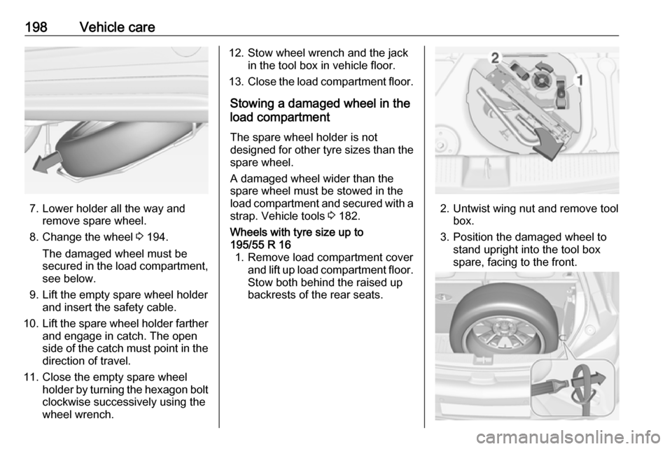
7. Lower holder all the way andremove spare wheel.
8. Change the wheel 3 194.
The damaged wheel must be
secured in the load compartment,
see below.
9. Lift the empty spare wheel holder and insert the safety cable.
10. Lift the spare wheel holder farther
and engage in catch. The open
side of the catch must point in the direction of travel.
11. Close the empty spare wheel holder by turning the hexagon boltclockwise successively using the
wheel wrench.
12. Stow wheel wrench and the jack in the tool box in vehicle floor.
13. Close the load compartment floor.
Stowing a damaged wheel in the
load compartment
The spare wheel holder is not
designed for other tyre sizes than the
spare wheel.
A damaged wheel wider than the
spare wheel must be stowed in the
load compartment and secured with a
strap. Vehicle tools 3 182.Wheels with tyre size up to
195/55 R 16 1. Remove load compartment cover and lift up load compartment floor.
Stow both behind the raised up
backrests of the rear seats.
2. Untwist wing nut and remove tool box.
3. Position the damaged wheel to stand upright into the tool box
spare, facing to the front.
Page 202 of 239
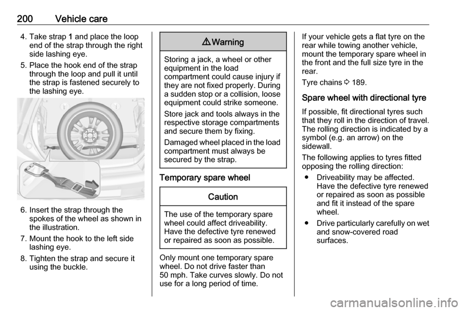
200Vehicle care4. Take strap 1 and place the loop
end of the strap through the right
side lashing eye.
5. Place the hook end of the strap through the loop and pull it until
the strap is fastened securely to
the lashing eye.
6. Insert the strap through the spokes of the wheel as shown in
the illustration.
7. Mount the hook to the left side lashing eye.
8. Tighten the strap and secure it using the buckle.
9 Warning
Storing a jack, a wheel or other
equipment in the load
compartment could cause injury if they are not fixed properly. During a sudden stop or a collision, looseequipment could strike someone.
Store jack and tools always in the
respective storage compartments
and secure them by fixing.
Damaged wheel placed in the load
compartment must always be
secured by the strap.
Temporary spare wheel
Caution
The use of the temporary spare
wheel could affect driveability.
Have the defective tyre renewed
or repaired as soon as possible.
Only mount one temporary spare
wheel. Do not drive faster than
50 mph. Take curves slowly. Do not
use for a long period of time.
If your vehicle gets a flat tyre on the
rear while towing another vehicle,
mount the temporary spare wheel in
the front and the full size tyre in the
rear.
Tyre chains 3 189.
Spare wheel with directional tyre If possible, fit directional tyres such
that they roll in the direction of travel.
The rolling direction is indicated by a
symbol (e.g. an arrow) on the
sidewall.
The following applies to tyres fitted
opposing the rolling direction:
● Driveability may be affected. Have the defective tyre renewed
or repaired as soon as possible
and fit it instead of the spare
wheel.
● Drive particularly carefully on wet
and snow-covered road
surfaces.
Page 204 of 239
202Vehicle care3. Connect the black lead to thenegative terminal of the booster
battery.
4. Connect the other end of the black
lead to a vehicle grounding point,
such as the engine block or an
engine mounting bolt. Connect as far away from the discharged
vehicle battery as possible,
however at least 60 cm.
Route the leads so that they cannot
catch on rotating parts in the engine
compartment.
To start the engine: 1. Start the engine of the vehicle providing the jump.
2. After five minutes, start the other engine. Start attempts should be
made for no longer than
15 seconds at an interval of one minute.
3. Allow both engines to idle for approx. three minutes with the
leads connected.4. Switch on electrical consumers (e.g. headlights, heated rear
window) of the vehicle receiving
the jump start.
5. Reverse above sequence exactly when removing leads.Towing
Towing the vehicle The towing eye is stowed with the
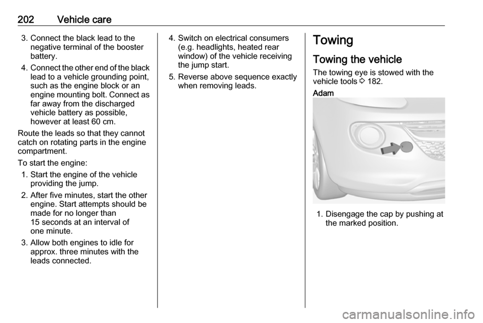
vehicle tools 3 182.Adam
1. Disengage the cap by pushing at
the marked position.
Page 205 of 239

Vehicle care203
2. Screw in the towing eye as far asit will go until it stops in a
horizontal position.
3. Attach a tow rope – or better still a
tow rod – to the towing eye.
Adam Rocks
1. Disengage the small cap with a screwdriver at the marked
position.
2. Screw in the towing eye as far as it will go until it stops in a
horizontal position.
3. Attach a tow rope – or better still a
tow rod – to the towing eye.General
The towing eye must only be used for
towing and not for recovering the
vehicle.
Switch on ignition to release steering
wheel lock and to permit operation of
brake lights, horn and windscreen
wiper.
Transmission in neutral.Caution
Drive slowly. Do not drive jerkily.
Excessive tractive force can
damage the vehicle.
When the engine is not running,
considerably more force is needed to
brake and steer.
To prevent the entry of exhaust gases from the towing vehicle, switch on the
air recirculation and close the
windows.
Page 206 of 239
204Vehicle careVehicles with manual transmission
automated: the vehicle must only be
towed facing forwards with the front
axle raised off the ground.
Seek the assistance of a workshop. After towing, unscrew the towing eye.
Insert cap and engage in the front
bumper.
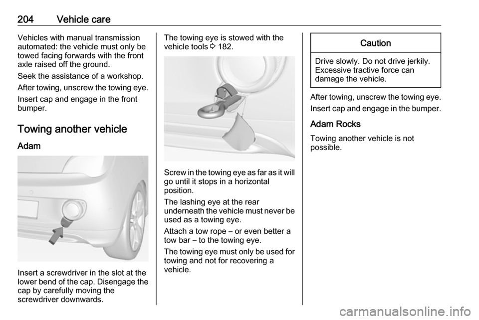
Towing another vehicle Adam
Insert a screwdriver in the slot at the
lower bend of the cap. Disengage the cap by carefully moving the
screwdriver downwards.
The towing eye is stowed with the
vehicle tools 3 182.
Screw in the towing eye as far as it will
go until it stops in a horizontal
position.
The lashing eye at the rear
underneath the vehicle must never be used as a towing eye.
Attach a tow rope – or even better a
tow bar – to the towing eye.
The towing eye must only be used for
towing and not for recovering a
vehicle.
Caution
Drive slowly. Do not drive jerkily.
Excessive tractive force can
damage the vehicle.
After towing, unscrew the towing eye.
Insert cap and engage in the bumper.
Adam Rocks
Towing another vehicle is not
possible.
Page 237 of 239

235Seat belt ........................................ 8
Seat belt reminder .......................83
Seat belts ..................................... 37
Seat folding .................................. 35
Seat heating ................................. 36
Seat position ................................ 33
Selector lever ............................. 131
Service ....................................... 122
Service display ............................ 80
Service information ....................209
Service vehicle soon .................... 85
Side airbag system ......................43
Side blind spot alert ....................151
Sidelights .................................... 105
Side turn signal lights ................175
Software acknowledgement .......227
Spare wheel ............................... 196
Speed limiter............................... 141
Speedometer ............................... 78
Starting and operating ................124
Starting off ................................... 16
Starting the engine ............125, 131
Steering ...................................... 124
Steering wheel adjustment ......9, 70
Steering wheel controls ...............70
Stop-start system........................ 126
Storage ......................................... 51
Storage compartments .................51
Sunroof ........................................ 31Sun visors .................................... 30
Symbols ......................................... 4
T
Tachometer ................................. 78
Tail lights ................................... 172
Three-point seat belt .................... 38
Tools .......................................... 182
Top-tether fastening eyes ............50
Towing ........................................ 202
Towing another vehicle .............204
Towing the vehicle .....................202
Traction Control system ............. 136
Transmission ............................... 16
Transmission display .................131
Tread depth ............................... 188
Trip odometer .............................. 78
Turn and lane-change signals ...108
Turn signal ................................... 83
Tyre chains ................................ 189
Tyre designations ......................183
Tyre pressure ............................ 184
Tyre pressure monitoring system ............................... 87, 185
Tyre pressures ........................... 223
Tyre repair kit ............................. 190
U Ultrasonic parking assist ...... 86, 142
Upholstery .................................. 207
Uplevel-Display............................. 88Upshift .......................................... 86
Using this manual ..........................3
V Vehicle battery ........................... 165
Vehicle checks............................ 162
Vehicle data ................................ 214
Vehicle data recording and privacy ..................................... 229
Vehicle dimensions .................... 221
Vehicle Identification Number ....212
Vehicle jack ................................ 182
Vehicle messages .......................95
Vehicle personalisation ...............98
Vehicle security ............................ 25
Vehicle specific data ......................3
Vehicle storage ........................... 161
Vehicle tools ............................... 182
Vehicle unlocking ........................... 6
Vehicle weight ........................... 220
Ventilation ................................... 113
W
Warning chimes ........................... 97
Warning lights ............................... 78
Warning triangle .......................... 66
Washer and wiper systems .........14
Washer fluid ............................... 164
Wheel changing .........................194
Wheel covers ............................. 189
Wheels and tyres .......................183