ECU VAUXHALL ADAM 2018.5 Owner's Guide
[x] Cancel search | Manufacturer: VAUXHALL, Model Year: 2018.5, Model line: ADAM, Model: VAUXHALL ADAM 2018.5Pages: 245, PDF Size: 7.4 MB
Page 141 of 245

Driving and operating139ParkingThe most recently engaged gear (see
transmission display) remains
engaged when switching off ignition. With N, no gear is engaged.
Therefore always apply the parking
brake when switching off ignition. If
parking brake is not applied, P flashes
in the transmission display and the
key cannot be removed from the
ignition switch. P stops flashing in the
transmission display as soon as the
parking brake is slightly applied.
When the ignition is switched off, the
transmission no longer responds to
movement of the selector lever.
Tyre pressure monitoring system
To start the sensor matching process of the tyre pressure monitoring
system, the selector lever must be
moved and held in position N for
5 seconds. P illuminates in the
transmission display to indicate that
the sensor matching process can be
started.
Tyre pressure monitoring system 3 189.Manual mode
If a higher gear is selected when the
engine speed is too low, or a lower
gear when the speed is too high, the
shift is not executed. This prevents
the engine from running at too low or too high an engine speed. A warning
message is displayed in the Driver
Information Centre.
Vehicle messages 3 98.
If engine speed is too low, the
transmission automatically shifts to a
lower gear.
If engine speed is too high, the
transmission only switches to a higher gear via kickdown.
When + or - is selected in automatic
mode, the transmission switches to
manual mode and shifts accordingly.
Gear shift indication
The symbol R, with a number
alongside it, is indicated when
gearshifting is recommended for fuel
saving reasons.
Shift indication appears only in
manual mode.Electronic driving
programmes
● Following a cold start, the operating temperature
programme increases engine
speed to quickly bring the
catalytic converter to the required
temperature.
● The adaptive programme tailors gearshifting to the driving
conditions, e.g. greater load or gradients.
Kickdown If the accelerator pedal is pressed
down completely in automatic mode, the transmission shifts to a lower gear
depending on engine speed.
Fault
To prevent damage to the manual transmission automated, the clutch is
engaged automatically at high clutch
temperatures.
Page 166 of 245

164Driving and operatingPress the button at the liquid gas
supply point. The filling system stops
or begins to run slowly when 80% of
the tank volume is reached
(maximum fill level).
Release button on filling system and
the filling process stops. Release the
locking lever and remove the filler
nozzle. A small quantity of liquid gas
may escape.
Remove adapter and stow securely in
vehicle.
Fit protective cap to prevent the
penetration of foreign bodies into the
filler opening and the system.9 Warning
Due to the system design, an
escape of liquid gas after
releasing the locking lever is
unavoidable. Avoid inhaling.
9 Warning
The liquid gas tank should only be
filled to 80% capacity, for safety
reasons.
The multivalve on the liquid gas tank
automatically limits the fill quantity. If
a larger quantity is added, we
recommend not exposing the vehicle
to the sun until the excess amount
has been used up.
Fuel filler cap
Only use genuine fuel filler caps.
Page 169 of 245
Vehicle care167Vehicle checks
Performing work9 Warning
Only perform engine compartment
checks when the ignition is off.
The cooling fan may start
operating even if the ignition is off.
9 Danger
The ignition system uses
extremely high voltage. Do not
touch.
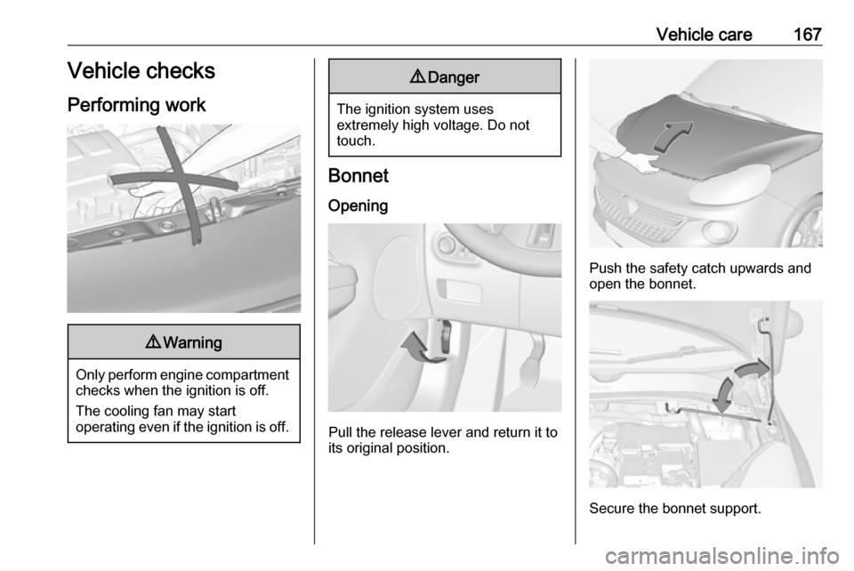
Bonnet
Opening
Pull the release lever and return it to
its original position.
Push the safety catch upwards and open the bonnet.
Secure the bonnet support.
Page 179 of 245
Vehicle care177
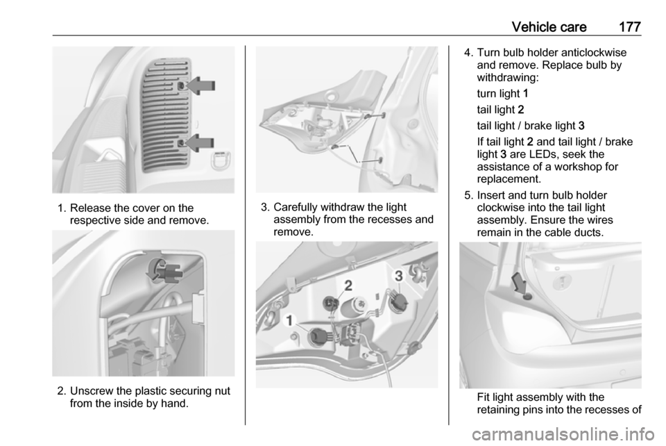
1. Release the cover on therespective side and remove.
2. Unscrew the plastic securing nut from the inside by hand.
3. Carefully withdraw the lightassembly from the recesses and
remove.
4. Turn bulb holder anticlockwise and remove. Replace bulb by
withdrawing:
turn light 1
tail light 2
tail light / brake light 3
If tail light 2 and tail light / brake
light 3 are LEDs, seek the
assistance of a workshop for
replacement.
5. Insert and turn bulb holder clockwise into the tail light
assembly. Ensure the wires
remain in the cable ducts.
Fit light assembly with the
retaining pins into the recesses of
Page 180 of 245
178Vehicle carethe vehicle body and tighten the
plastic securing nut from inside
the load compartment. Pull the
circular gasket over the recess in
the lamp housing.
Close cover and engage.
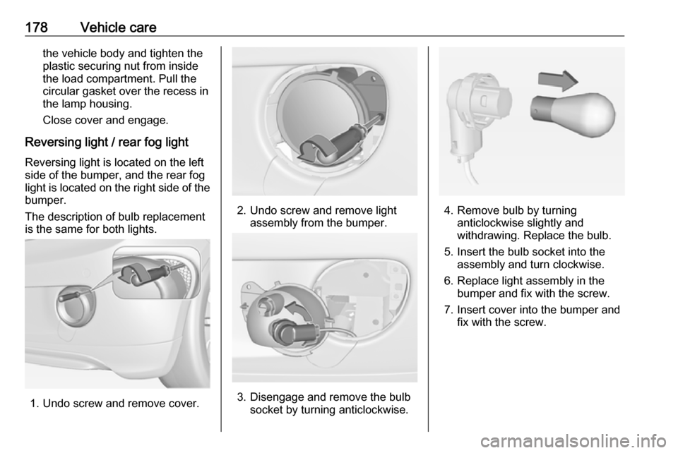
Reversing light / rear fog light Reversing light is located on the left
side of the bumper, and the rear fog
light is located on the right side of the
bumper.
The description of bulb replacement
is the same for both lights.
1. Undo screw and remove cover.
2. Undo screw and remove light assembly from the bumper.
3. Disengage and remove the bulbsocket by turning anticlockwise.
4. Remove bulb by turninganticlockwise slightly and
withdrawing. Replace the bulb.
5. Insert the bulb socket into the assembly and turn clockwise.
6. Replace light assembly in the bumper and fix with the screw.
7. Insert cover into the bumper and fix with the screw.
Page 189 of 245
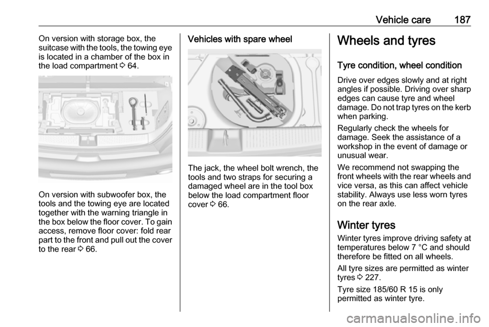
Vehicle care187On version with storage box, the
suitcase with the tools, the towing eye
is located in a chamber of the box in
the load compartment 3 64.
On version with subwoofer box, the
tools and the towing eye are located
together with the warning triangle in
the box below the floor cover. To gain
access, remove floor cover: fold rear
part to the front and pull out the cover to the rear 3 66.
Vehicles with spare wheel
The jack, the wheel bolt wrench, the
tools and two straps for securing a
damaged wheel are in the tool box below the load compartment floor
cover 3 66.
Wheels and tyres
Tyre condition, wheel condition Drive over edges slowly and at right
angles if possible. Driving over sharp
edges can cause tyre and wheel
damage. Do not trap tyres on the kerb when parking.
Regularly check the wheels for
damage. Seek the assistance of a
workshop in the event of damage or
unusual wear.
We recommend not swapping the
front wheels with the rear wheels and vice versa, as this can affect vehicle
stability. Always use less worn tyres
on the rear axle.
Winter tyres
Winter tyres improve driving safety at temperatures below 7 °C and should
therefore be fitted on all wheels.
All tyre sizes are permitted as winter
tyres 3 227.
Tyre size 185/60 R 15 is only
permitted as winter tyre.
Page 201 of 245
Vehicle care199
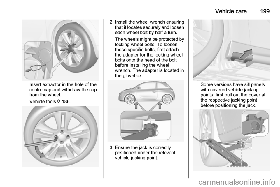
Insert extractor in the hole of the
centre cap and withdraw the cap
from the wheel.
Vehicle tools 3 186.
2. Install the wheel wrench ensuring
that it locates securely and loosen
each wheel bolt by half a turn.
The wheels might be protected by
locking wheel bolts. To loosen
these specific bolts, first attach
the adapter for the locking wheel
bolts onto the head of the bolt
before installing the wheel
wrench. The adapter is located in
the glovebox.
3. Ensure the jack is correctly positioned under the relevant
vehicle jacking point.
Some versions have sill panels
with covered vehicle jacking points: first pull out the cover at
the respective jacking point
before positioning the jack.
Page 202 of 245
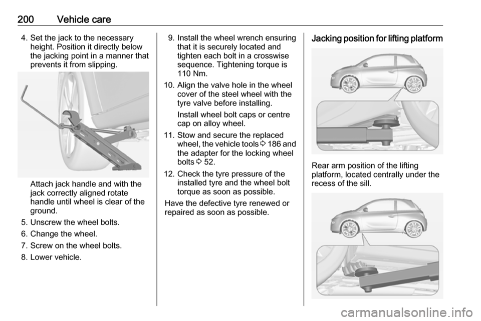
200Vehicle care4. Set the jack to the necessaryheight. Position it directly below
the jacking point in a manner that
prevents it from slipping.
Attach jack handle and with the
jack correctly aligned rotate handle until wheel is clear of theground.
5. Unscrew the wheel bolts.
6. Change the wheel.
7. Screw on the wheel bolts.
8. Lower vehicle.
9. Install the wheel wrench ensuring that it is securely located and
tighten each bolt in a crosswise
sequence. Tightening torque is
110 Nm.
10. Align the valve hole in the wheel cover of the steel wheel with the
tyre valve before installing.
Install wheel bolt caps or centre
cap on alloy wheel.
11. Stow and secure the replaced wheel, the vehicle tools 3 186 and
the adapter for the locking wheel
bolts 3 52.
12. Check the tyre pressure of the installed tyre and the wheel bolt
torque as soon as possible.
Have the defective tyre renewed or
repaired as soon as possible.Jacking position for lifting platform
Rear arm position of the lifting
platform, located centrally under the
recess of the sill.
Page 204 of 245
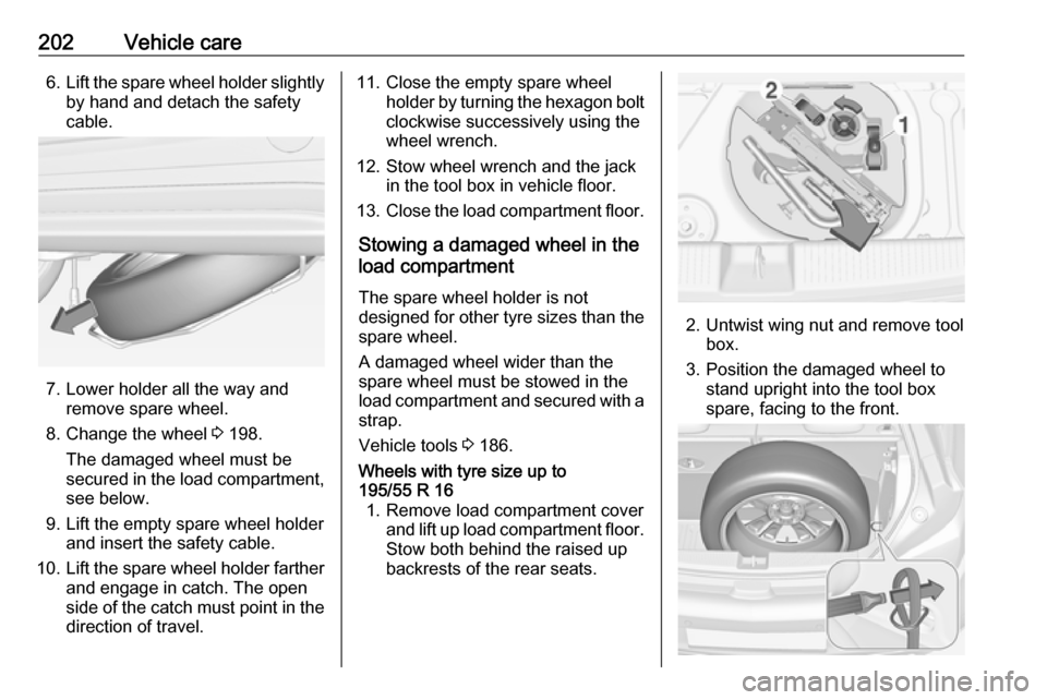
202Vehicle care6.Lift the spare wheel holder slightly
by hand and detach the safety
cable.
7. Lower holder all the way and remove spare wheel.
8. Change the wheel 3 198.
The damaged wheel must be
secured in the load compartment,
see below.
9. Lift the empty spare wheel holder and insert the safety cable.
10. Lift the spare wheel holder farther
and engage in catch. The open
side of the catch must point in the direction of travel.
11. Close the empty spare wheel holder by turning the hexagon boltclockwise successively using the
wheel wrench.
12. Stow wheel wrench and the jack in the tool box in vehicle floor.
13. Close the load compartment floor.
Stowing a damaged wheel in the
load compartment
The spare wheel holder is not
designed for other tyre sizes than the
spare wheel.
A damaged wheel wider than the
spare wheel must be stowed in the
load compartment and secured with a strap.
Vehicle tools 3 186.Wheels with tyre size up to
195/55 R 16 1. Remove load compartment cover and lift up load compartment floor.
Stow both behind the raised up
backrests of the rear seats.
2. Untwist wing nut and remove tool box.
3. Position the damaged wheel to stand upright into the tool box
spare, facing to the front.
Page 205 of 245
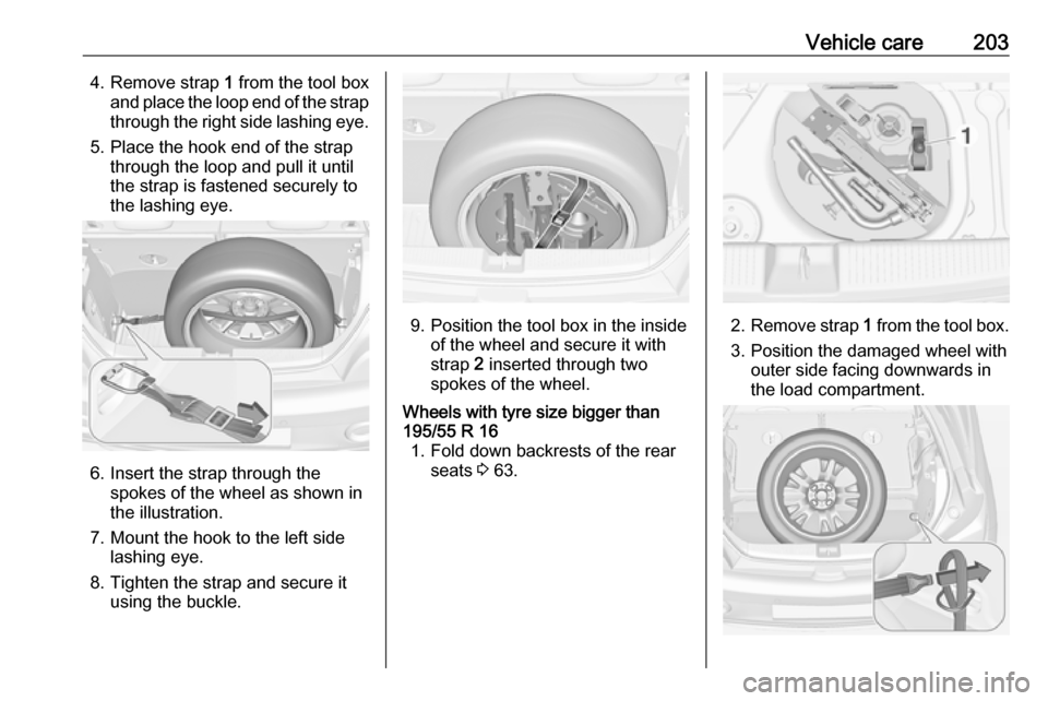
Vehicle care2034. Remove strap 1 from the tool box
and place the loop end of the strap through the right side lashing eye.
5. Place the hook end of the strap through the loop and pull it until
the strap is fastened securely to
the lashing eye.
6. Insert the strap through the spokes of the wheel as shown in
the illustration.
7. Mount the hook to the left side lashing eye.
8. Tighten the strap and secure it using the buckle.
9. Position the tool box in the insideof the wheel and secure it with
strap 2 inserted through two
spokes of the wheel.
Wheels with tyre size bigger than
195/55 R 16 1. Fold down backrests of the rear seats 3 63.
2. Remove strap 1 from the tool box.
3. Position the damaged wheel with outer side facing downwards in
the load compartment.