warning VAUXHALL ADAM 2018 Owner's Guide
[x] Cancel search | Manufacturer: VAUXHALL, Model Year: 2018, Model line: ADAM, Model: VAUXHALL ADAM 2018Pages: 241, PDF Size: 7.34 MB
Page 70 of 241
68StorageLoading information
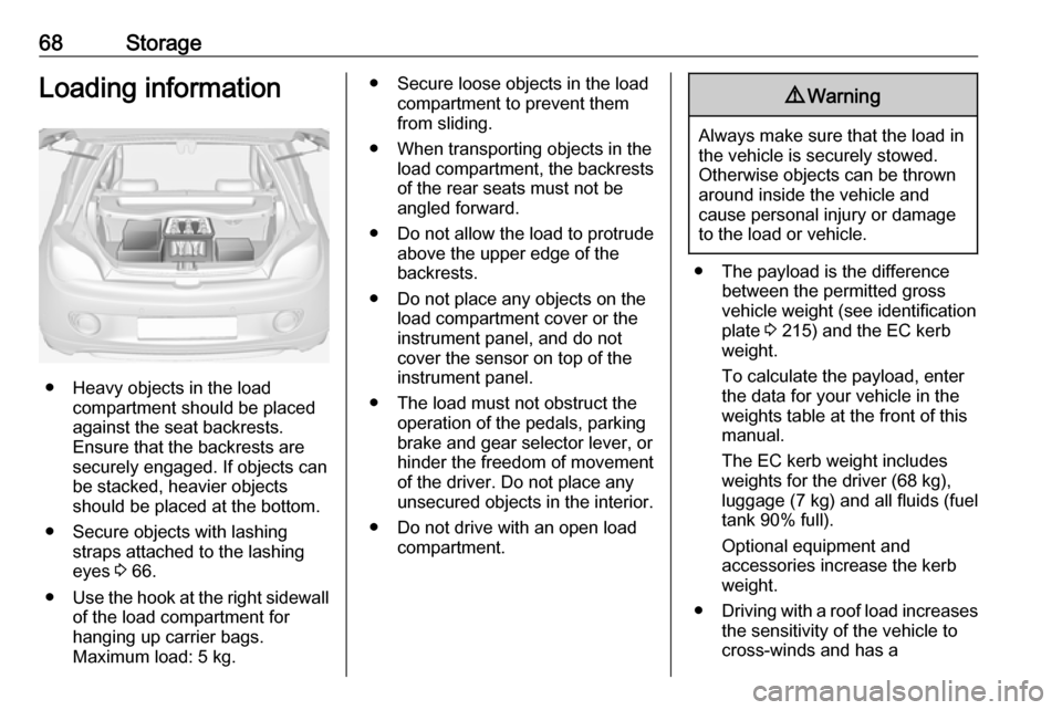
● Heavy objects in the loadcompartment should be placed
against the seat backrests.
Ensure that the backrests are
securely engaged. If objects can
be stacked, heavier objects
should be placed at the bottom.
● Secure objects with lashing straps attached to the lashing
eyes 3 66.
● Use the hook at the right sidewall
of the load compartment for
hanging up carrier bags.
Maximum load: 5 kg.
● Secure loose objects in the load compartment to prevent themfrom sliding.
● When transporting objects in the load compartment, the backrestsof the rear seats must not be
angled forward.
● Do not allow the load to protrude above the upper edge of the
backrests.
● Do not place any objects on the load compartment cover or theinstrument panel, and do not
cover the sensor on top of the instrument panel.
● The load must not obstruct the operation of the pedals, parking
brake and gear selector lever, or
hinder the freedom of movement of the driver. Do not place any
unsecured objects in the interior.
● Do not drive with an open load compartment.9Warning
Always make sure that the load in
the vehicle is securely stowed.
Otherwise objects can be thrown
around inside the vehicle and
cause personal injury or damage
to the load or vehicle.
● The payload is the difference between the permitted gross
vehicle weight (see identification
plate 3 215) and the EC kerb
weight.
To calculate the payload, enter
the data for your vehicle in the
weights table at the front of this
manual.
The EC kerb weight includes
weights for the driver (68 kg),
luggage (7 kg) and all fluids (fuel
tank 90% full).
Optional equipment and
accessories increase the kerb
weight.
● Driving with a roof load increases
the sensitivity of the vehicle to
cross-winds and has a
Page 72 of 241

70Instruments and controlsInstruments and
controlsControls ....................................... 71
Steering wheel adjustment ........71
Steering wheel controls .............71
Heated steering wheel ...............71
Horn ........................................... 72
Windscreen wiper/washer .........72
Rear window wiper/washer .......73
Outside temperature ..................74
Clock ......................................... 75
Power outlets ............................. 76
Inductive charging .....................77
Cigarette lighter ......................... 78
Ashtrays .................................... 78
Warning lights, gauges and indi‐ cators ........................................... 79
Instrument cluster ......................79
Speedometer ............................. 79
Odometer .................................. 79
Trip odometer ............................ 79
Tachometer ............................... 79
Fuel gauge ................................ 80
Fuel selector .............................. 80
Engine coolant temperature gauge ....................................... 81Service display.......................... 82
Control indicators ......................83
Turn signal ................................. 85
Seat belt reminder .....................85
Airbag and belt tensioners .........86
Airbag deactivation ....................86
Charging system .......................86
Malfunction indicator light ..........87
Service vehicle soon .................87
Brake and clutch system ...........87
Operate pedal ............................ 87
Antilock brake system (ABS) .....88
Upshift ....................................... 88
Power steering .......................... 88
Ultrasonic parking assist ...........88
Electronic Stability Control off ...88
Electronic Stability Control and Traction Control system ...........88
Tyre pressure monitoring system ...................................... 89
Engine oil pressure ....................89
Low fuel ..................................... 89
Immobiliser ................................ 90
Exterior light .............................. 90
High beam ................................. 90
Rear fog light ............................. 90
Cruise control ............................ 90
Door open .................................. 90
Information displays .....................90
Driver Information Centre ..........90Colour-Info-Display ....................95
Graphic-Info-Display ..................96
Vehicle messages ........................97
Warning chimes .........................99
Battery voltage .......................... 99
Vehicle personalisation ..............100
Telematics service .....................104
OnStar ..................................... 104
Page 77 of 241
Instruments and controls75If outside temperature drops to 3 °C,
a warning message is displayed in the
Driver Information Centre.9 Warning
The road surface may already be
icy even though the display
indicates a few degrees above 0
°C.
Clock
Graphic-Info Display
Press CONFIG to open the Settings
menu.
Scroll through the list and select the
menu item Time Date to display the
respective submenu.
Notice
For a detailed description of menu
operation, refer to the Infotainment
manual.
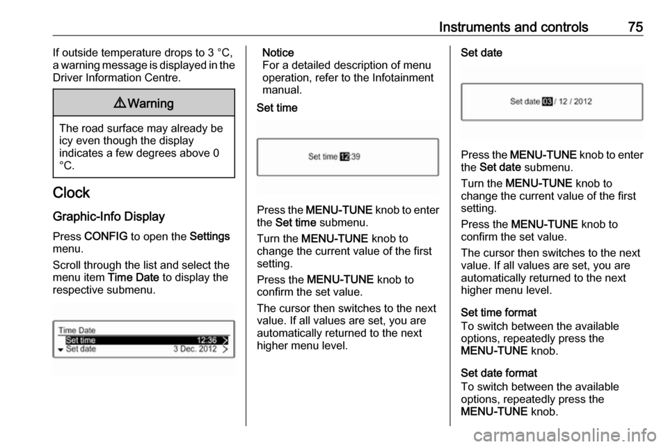
Set time
Press the MENU-TUNE knob to enter
the Set time submenu.
Turn the MENU-TUNE knob to
change the current value of the first setting.
Press the MENU-TUNE knob to
confirm the set value.
The cursor then switches to the next
value. If all values are set, you are
automatically returned to the next
higher menu level.
Set date
Press the MENU-TUNE knob to enter
the Set date submenu.
Turn the MENU-TUNE knob to
change the current value of the first setting.
Press the MENU-TUNE knob to
confirm the set value.
The cursor then switches to the next
value. If all values are set, you are
automatically returned to the next
higher menu level.
Set time format
To switch between the available
options, repeatedly press the
MENU-TUNE knob.
Set date format
To switch between the available
options, repeatedly press the
MENU-TUNE knob.
Page 79 of 241
Instruments and controls77With ignition off, the power outlet is
deactivated. Additionally, the power outlet is deactivated in the event of
low vehicle battery voltage.
Electrical accessories that are
connected must comply with the
electromagnetic compatibility
requirements laid down in
DIN VDE 40 839.
Do not connect any current-delivering
accessories, e.g. electrical charging
devices or batteries.
Do not damage the outlet by using
unsuitable plugs.
Stop-start system 3 129.
Inductive charging9 Warning
Inductive charging can affect the
operation of implanted
pacemakers or other medical
devices. If applicable, seek
medical advice before using the
inductive charging device.
9 Warning
Remove any metal objects from
the charging device before
charging a mobile phone, as these
objects could become very hot.
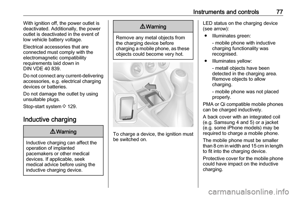
To charge a device, the ignition must
be switched on.
LED status on the charging device
(see arrow):
● Illuminates green: - mobile phone with inductive
charging functionality was
recognised.
● Illuminates yellow: - metall objects have been
detected in the charging area.
Remove objects to allow
charging.
- mobile phone was not placed
properly.
PMA or Qi compatible mobile phones can be charged inductively.
A back cover with an integrated coil (e.g. Samsung 4 and 5) or a jacket
(e.g. some iPhone models) may be
required to charge a mobile phone.
The mobile phone must be smaller
than 8 cm in width and 15 cm in length
to fit into the charging device.
Protective cover for the mobile phone could have impact on the inductive
charging.
Page 81 of 241
Instruments and controls79Warning lights, gauges
and indicators
Instrument cluster
The needles of the instruments briefly
rotate to the end position when the
ignition is switched on.
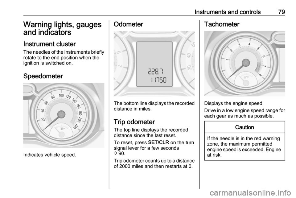
Speedometer
Indicates vehicle speed.
Odometer
The bottom line displays the recorded distance in miles.
Trip odometer The top line displays the recordeddistance since the last reset.
To reset, press SET/CLR on the turn
signal lever for a few seconds
3 90.
Trip odometer counts up to a distance
of 2000 miles and then restarts at 0.
Tachometer
Displays the engine speed.
Drive in a low engine speed range for each gear as much as possible.
Caution
If the needle is in the red warning
zone, the maximum permitted
engine speed is exceeded. Engine at risk.
Page 83 of 241
Instruments and controls81When switching automatically
between petrol or gas operation, a
brief delay of engine tractive power
may be noticeable.
Every six months, run the petrol tank
down until control indicator Y
illuminates, then refuel. This helps
maintain fuel quality and system
function for petrol operation.
Fill the tank completely at regular
intervals to prevent corrosion in the
tank.
Fuel for liquid gas operation 3 157.
Faults and remedies
If gas mode is not possible, check the following:
● Is there enough liquid gas present?
● Is there enough petrol present for
starting?
Due to extreme temperatures in
combination with the gas
composition, it may take slightly
longer before the system switches
from petrol to gas mode.In extreme situations, the system may
also switch back to petrol mode if the
minimum requirements are not
fulfilled. If conditions allow, it might be possible to manually switch back to
liquid gas operation.
Seek the assistance of a workshop in
the event of all other faults.Caution
Repairs and adjustments may only
be made by trained specialists in
order to maintain the safety and
warranty on the LPG system.
Liquid gas is given a particular odour
(odorised) so that any leaks can be
detected easily.
9 Warning
If you smell gas in the vehicle or in
the immediate vicinity, switch to petrol mode immediately. No
smoking. No naked flames or
ignition sources.
If the gas odour persists, do not start
the engine. Have the cause of the
fault remedied by a workshop.
When using underground car parks,
follow the instructions of the operator
and local laws.
Notice
In the event of an accident, switch off
the ignition and lights.
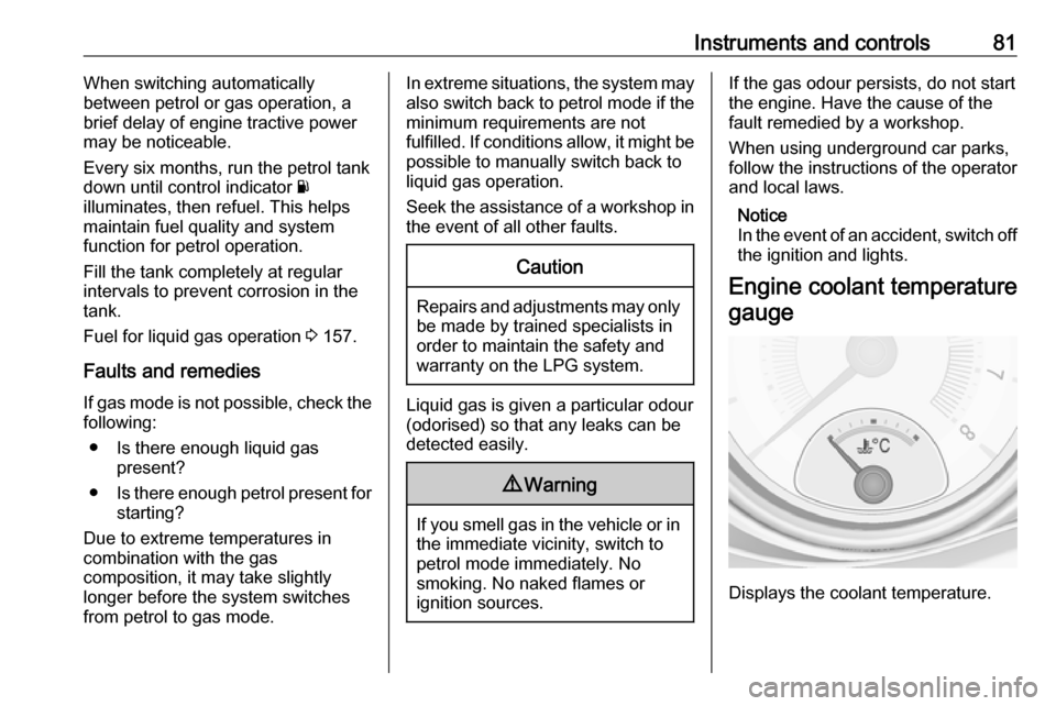
Engine coolant temperature gauge
Displays the coolant temperature.
Page 85 of 241

Instruments and controls83Next serviceWhen the system has calculated that
engine oil life has diminished, a
warning message appears in the
Driver Information Centre. Have
engine oil and filter changed by a
workshop within one week or
300 miles (whichever occurs first).
Driver Information Centre 3 90.
Service information 3 210.
Control indicators
The control indicators described are
not present in all vehicles. The
description applies to all instrument
versions. Depending on the
equipment, the position of the control indicators may vary.
When the ignition is switched on,
most control indicators will illuminate
briefly as a functionality test.
The control indicator colours mean:red:danger, important reminderyellow:warning, information, faultgreen:confirmation of activationblue:confirmation of activationwhite:confirmation of activation
Page 87 of 241
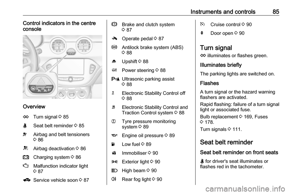
Instruments and controls85Control indicators in the centre
console
Overview
OTurn signal 3 85XSeat belt reminder 3 85vAirbag and belt tensioners
3 86VAirbag deactivation 3 86pCharging system 3 86ZMalfunction indicator light
3 87gService vehicle soon 3 87RBrake and clutch system
3 87-Operate pedal 3 87uAntilock brake system (ABS)
3 88[Upshift 3 88cPower steering 3 88rUltrasonic parking assist
3 88nElectronic Stability Control off
3 88bElectronic Stability Control and
Traction Control system 3 88wTyre pressure monitoring
system 3 89IEngine oil pressure 3 89YLow fuel 3 89dImmobiliser 3 908Exterior light 3 90CHigh beam 3 90rRear fog light 3 90mCruise control 3 90hDoor open 3 90
Turn signal
O illuminates or flashes green.
Illuminates briefly
The parking lights are switched on.
Flashes
A turn signal or the hazard warning flashers are activated.
Rapid flashing: failure of a turn signal light or associated fuse.
Bulb replacement 3 169, Fuses
3 178.
Turn signals 3 111.
Seat belt reminder
Seat belt reminder on front seats
X for driver's seat illuminates or
flashes red in the tachometer.
Page 88 of 241
86Instruments and controlsk for front passenger seat illuminates
or flashes red in the centre console,
when the seat is occupied.
Illuminates
After the ignition has been switched
on until the seat belt has been
fastened.
Flashes
After having started the engine for a
maximum of 100 seconds until the
seat belt has been fastened.
Fastening the seat belt 3 38.
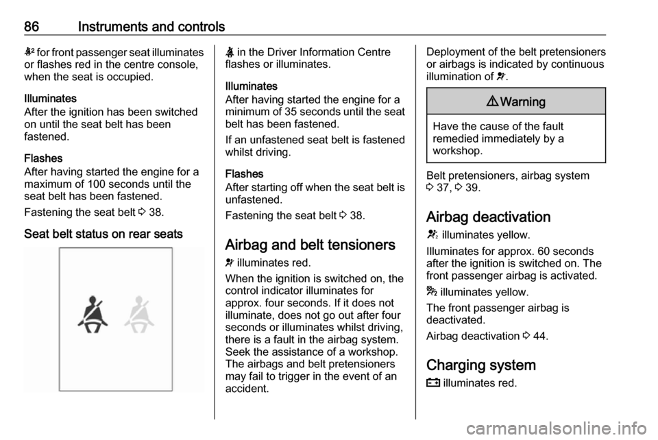
Seat belt status on rear seatsX in the Driver Information Centre
flashes or illuminates.
Illuminates
After having started the engine for a
minimum of 35 seconds until the seat
belt has been fastened.
If an unfastened seat belt is fastened
whilst driving.
Flashes
After starting off when the seat belt is unfastened.
Fastening the seat belt 3 38.
Airbag and belt tensioners
v illuminates red.
When the ignition is switched on, the control indicator illuminates for
approx. four seconds. If it does not
illuminate, does not go out after four
seconds or illuminates whilst driving,
there is a fault in the airbag system.
Seek the assistance of a workshop.
The airbags and belt pretensioners
may fail to trigger in the event of an
accident.Deployment of the belt pretensioners
or airbags is indicated by continuous
illumination of v.9 Warning
Have the cause of the fault
remedied immediately by a
workshop.
Belt pretensioners, airbag system
3 37, 3 39.
Airbag deactivation
V illuminates yellow.
Illuminates for approx. 60 seconds
after the ignition is switched on. The
front passenger airbag is activated.
* illuminates yellow.
The front passenger airbag is
deactivated.
Airbag deactivation 3 44.
Charging system p illuminates red.
Page 89 of 241

Instruments and controls87Illuminates when the ignition is
switched on and extinguishes shortly after the engine starts.
Illuminates when the engine is
running
Stop, switch off engine. Vehicle
battery is not charging. Engine
cooling may be interrupted. The
brake servo unit may cease to be effective. Seek the assistance of a
workshop.
Malfunction indicator light Z illuminates or flashes yellow.
Illuminates when the ignition is
switched on and extinguishes shortly
after the engine starts.
Illuminates when the engine is
running
Fault in the emission control system. The permitted emission limits may be
exceeded. Seek the assistance of a
workshop immediately.Flashes when the engine is
running
Fault that could lead to catalyticconverter damage. Ease up on the accelerator until the flashing stops.
Seek the assistance of a workshop
immediately.
Service vehicle soon
g illuminates yellow.
Additionally, a warning message is
displayed in the Driver Information
Centre.
The vehicle needs a service.
Seek the assistance of a workshop.
Vehicle messages 3 97.
Brake and clutch system R illuminates red.
The brake and clutch fluid level is too low, when manual parking brake is
not applied 3 167.9 Warning
Stop. Do not continue your
journey. Consult a workshop.
Illuminates when the manual parking
brake is applied and ignition is
switched on 3 138.
Operate pedal - illuminates or flashes yellow.
Illuminates
Clutch pedal must be depressed to
start the engine in Autostop mode.
Stop-start system 3 129.
Flashes
Clutch pedal must be depressed to
start the engine with the key 3 16,
3 128.
On some versions, the Driver
Information Centre indicates a
message to operate the clutch pedal
3 97.