ignition VAUXHALL ADAM 2019 Workshop Manual
[x] Cancel search | Manufacturer: VAUXHALL, Model Year: 2019, Model line: ADAM, Model: VAUXHALL ADAM 2019Pages: 223, PDF Size: 6.54 MB
Page 157 of 223
Vehicle care155Wiper blade replacement
Windscreen
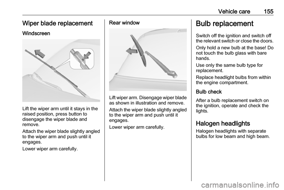
Lift the wiper arm until it stays in the
raised position, press button to
disengage the wiper blade and
remove.
Attach the wiper blade slightly angled
to the wiper arm and push until it
engages.
Lower wiper arm carefully.
Rear window
Lift wiper arm. Disengage wiper blade as shown in illustration and remove.
Attach the wiper blade slightly angled
to the wiper arm and push until it
engages.
Lower wiper arm carefully.
Bulb replacement
Switch off the ignition and switch off
the relevant switch or close the doors.
Only hold a new bulb at the base! Do not touch the bulb glass with bare
hands.
Use only the same bulb type for
replacement.
Replace headlight bulbs from within
the engine compartment.
Bulb check
After a bulb replacement switch on
the ignition, operate and check the
lights.
Halogen headlights Halogen headlights with separate
bulbs for low beam and high beam.
Page 166 of 223
164Vehicle care4. Pull bulb from bulb holder andreplace it.
5. Insert bulb holder into lamp housing and turn clockwise.
6. Insert lamp into bumper and allow
it to engage.
Interior lights
Have the following bulbs replaced by
a workshop:
● courtesy light, reading lights
● load compartment light
● dome light
● ambient light
● starlight panel
● instrument panel illuminationElectrical system
Fuses
Data on the replacement fuse must
match the data on the defective fuse.
There are two fuse boxes in the
vehicle:
● in the front left of the engine compartment,
● in left-hand drive vehicles behind
the light switch, or, in right-hand
drive vehicles, behind the
glovebox.
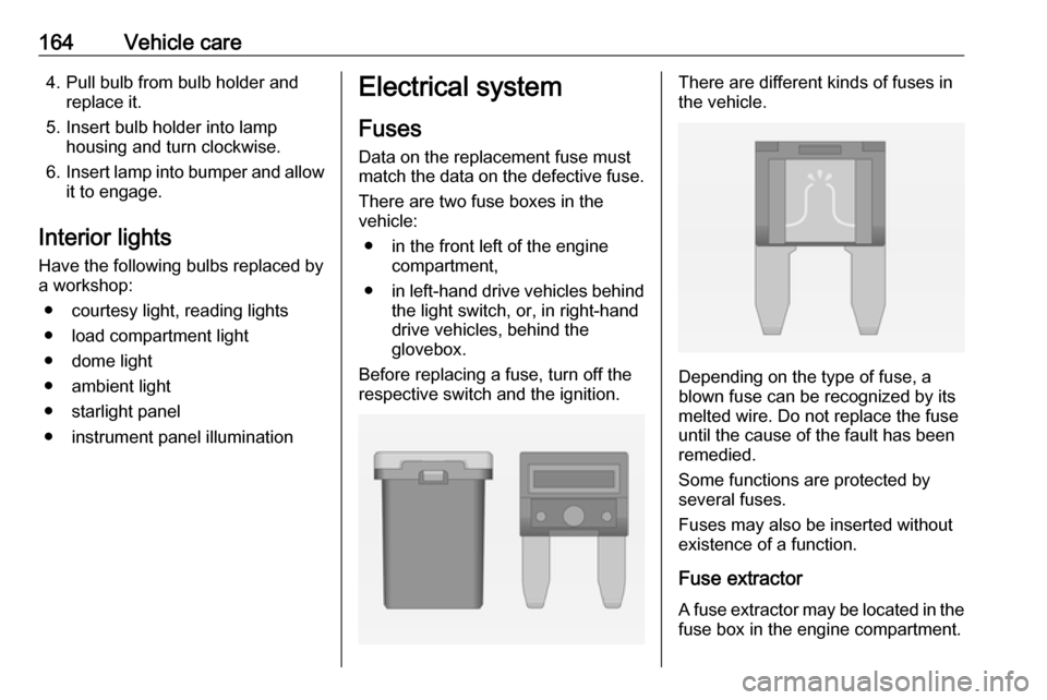
Before replacing a fuse, turn off the respective switch and the ignition.There are different kinds of fuses in
the vehicle.
Depending on the type of fuse, a
blown fuse can be recognized by its
melted wire. Do not replace the fuse until the cause of the fault has been
remedied.
Some functions are protected by
several fuses.
Fuses may also be inserted without existence of a function.
Fuse extractorA fuse extractor may be located in the
fuse box in the engine compartment.
Page 168 of 223

166Vehicle careNo.Circuit1Rear carrier2Exterior mirror switch3Body control module4Foldable power sunroof5ABS6Daytime running light left / low
beam left7–8Power window switch9Vehicle battery sensor10Headlamp levelling / Ignition11Rear wiper12Window defog13Daytime running light right / low
beam right14Exterior mirror heating15–No.Circuit16Fuel pump module / LPG
module17Interior mirror / Voltage
converter18Engine control module19Fuel pump20–21Solenoid canister purge22–23Ignition coils / Injectors24Washer system25Ambient light sensor / Rain light sensor26Engine sensors27Engine management28Engine control module / LPG
module29Engine control module30–No.Circuit31Left highbeam32Right highbeam33Engine control module34Horn35Air conditioning compressor
clutch36–
Page 170 of 223
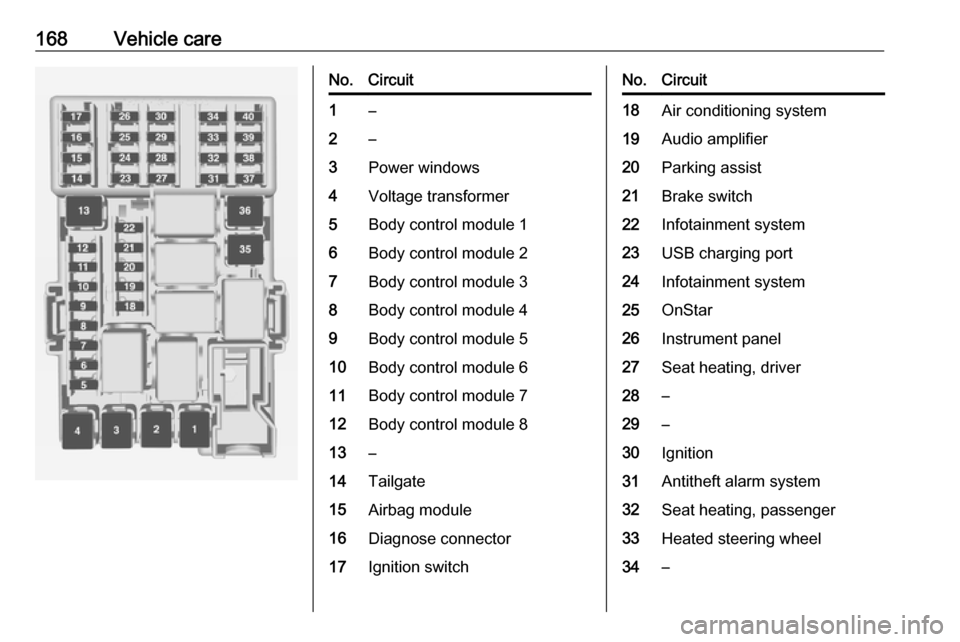
168Vehicle careNo.Circuit1–2–3Power windows4Voltage transformer5Body control module 16Body control module 27Body control module 38Body control module 49Body control module 510Body control module 611Body control module 712Body control module 813–14Tailgate15Airbag module16Diagnose connector17Ignition switchNo.Circuit18Air conditioning system19Audio amplifier20Parking assist21Brake switch22Infotainment system23USB charging port24Infotainment system25OnStar26Instrument panel27Seat heating, driver28–29–30Ignition31Antitheft alarm system32Seat heating, passenger33Heated steering wheel34–
Page 174 of 223

172Vehicle careThe tyre pressure tables show allpossible tyre combinations 3 206.
Identify the respective tyre.
For the tyres approved for your
vehicle, refer to the EEC Certificate of Conformity provided with your vehicle
or other national registration
documents.
The driver is responsible for correct
adjustment of tyre pressure.9 Warning
If the pressure is too low, this can
result in considerable tyre warm-
up and internal damage, leading to tread separation and even to tyre
blow-out at high speeds.
9 Warning
For specific tyres the
recommended tyre pressure as
shown in the tyre pressure table
may exceed the maximum tyre
pressure as indicated on the tyre.
Never exceed the maximum tyre
pressure as indicated on the tyre.
If the tyre pressure must be reduced
or increased, switch off ignition. After
adjusting tyre pressure switch on
ignition and select the relevant setting on the page Tyre load in the Driver
Information Centre 3 80.
Temperature dependency
The tyre pressure depends on the
temperature of the tyre. During
driving, tyre temperature and
pressure increase. Tyre pressure
values provided on the tyre
information label and tyre pressure
chart are valid for cold tyres, which
means at 20 °C.
The pressure increases by nearly
1.5 psi for a 10 °C temperature
increase. This must be considered
when warm tyres are checked.
The tyre pressure value displayed in
the Driver Information Centre shows
the real tyre pressure. A cooled down tyre will show a decreased value,
which does not indicate an air leak.Tyre pressure monitoring
system
The tyre pressure monitoring system
checks the pressure of all four tyres
once a minute when vehicle speed
exceeds a certain limit.Caution
Tyre pressure monitoring system
warns only about low tyre pressure condition and does not replace
regular tyre maintenance by the
driver.
All wheels must be equipped with pressure sensors and the tyres must
have the prescribed pressure.
Notice
In countries where the tyre pressure
monitoring system is legally
required, the use of wheels without
pressure sensors will invalidate the
vehicle operating permit.
The current tyre pressures can be
shown in the Vehicle Information
Menu in the Driver Information
Centre.
Page 175 of 223

Vehicle care173The menu can be selected by
pressing the buttons on the stalk.
Press MENU to select the Vehicle
Information Menu X.
Turn the adjuster wheel to select the
tyre pressure monitoring system.
System status and pressure warnings
are displayed by a message with the
corresponding tyre flashing in the
Driver Information Centre.
The system considers the tyre
temperature for the warnings.
Temperature dependency 3 171.
A detected low tyre pressure
condition is indicated by the control
indicator w 3 78.
If w illuminates, stop as soon as
possible and inflate the tyres as
recommended 3 206.
If
w flashes for 60-90 seconds then
illuminates continuously, there is a
fault in the system. Consult a
workshop.
After inflating, some driving may be
required to update the tyre pressure
values in the Driver Information
Centre. During this time w may
illuminate.
If w illuminates at lower temperatures
and extinguishes after some driving,
this could be an indicator for
approaching a low tyre pressure
condition. Check tyre pressure.
Vehicle messages 3 87.
If the tyre pressure must be reduced
or increased, switch off ignition.
Only mount wheels with pressure
sensors, otherwise the tyre pressure
will not be displayed and w
illuminates continuously.
A spare wheel or temporary spare
wheel is not equipped with pressure
sensors. The tyre pressure
monitoring system is not operational
for these tyres. Control indicator w
Page 176 of 223
174Vehicle careilluminates. For the further three
tyres, the system remains
operational.
The use of commercially-available liquid tyre repair kits can impair the
function of the system. Factory-
approved repair kits can be used.
Operating electronic devices or being close to facilities using similar wave
frequencies could disrupt the tyre
pressure monitoring system.
Each time the tyres are replaced, tyre
pressure monitoring system sensors
must be dismounted and serviced. For the screwed sensor; replace
valve core and sealing ring. For the
clipped sensor; replace complete
valve stem.
Vehicle loading status
Adjust tyre pressure to load condition according to the tyre information labelor tyre pressure chart 3 206, and
select the appropriate setting in the menu Tyre Load in the Driver
Information Centre, Vehicle
Information Menu 3 80 . This setting is
the reference for the tyre pressure
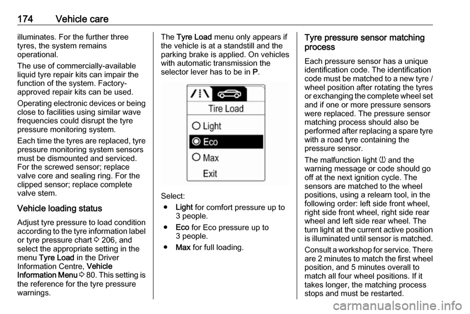
warnings.The Tyre Load menu only appears if
the vehicle is at a standstill and the parking brake is applied. On vehicles
with automatic transmission the
selector lever has to be in P.
Select:
● Light for comfort pressure up to
3 people.
● Eco for Eco pressure up to
3 people.
● Max for full loading.
Tyre pressure sensor matching
process
Each pressure sensor has a unique
identification code. The identification
code must be matched to a new tyre /
wheel position after rotating the tyres
or exchanging the complete wheel set and if one or more pressure sensors
were replaced. The pressure sensor
matching process should also be
performed after replacing a spare tyre
with a road tyre containing the
pressure sensor.
The malfunction light w and the
warning message or code should go
off at the next ignition cycle. The
sensors are matched to the wheel
positions, using a relearn tool, in the following order: left side front wheel,
right side front wheel, right side rear
wheel and left side rear wheel. The
turn light at the current active position
is illuminated until sensor is matched.
Consult a workshop for service. There are 2 minutes to match the first wheelposition, and 5 minutes overall to
match all four wheel positions. If it
takes longer, the matching process
stops and must be restarted.
Page 177 of 223

Vehicle care175The tyre pressure sensor matching
process is:
1. Apply the parking brake.
2. Turn the ignition on.
3. On vehicles with manual transmission: select neutral.
4. Use MENU on the stalk to select
the Vehicle Information Menu in
the Driver Information Centre.
5. Turn the adjuster wheel to scroll to
the tyre pressure menu.
6. Press SET/CLR to begin the
sensor matching process. A
message requesting acceptance
of the process should be
displayed.
7. Press SET/CLR again to confirm
the selection. The horn sounds
twice to indicate that the receiver
is in relearn mode.
8. Start with the left side front wheel.
9. Place the relearn tool against the tyre sidewall, near the valve stem.Then press the button to activate
the tyre pressure sensor. A hornchirp confirms that the sensor
identification code has been
matched to this wheel position.
10. Proceed to the right side front wheel, and repeat the procedure
in Step 9.
11. Proceed to the right side rear wheel, and repeat the procedure
in Step 9.
12. Proceed to the left side rear wheel, and repeat the procedure
in Step 9. The horn sounds twice
to indicate that the sensor
identification code has been
matched to the left side rear
wheel, and the tyre pressure
sensor matching process is no
longer active.
13. Turn off the ignition.
14. Set all four tyres to the recommended air pressure level
as indicated on the tyre
information label.
15. Ensure the tyre loading status is set according to the selected
pressure 3 80.Tread depth
Check tread depth at regular
intervals.
Tyres should be replaced for safety
reasons at a tread depth of 2-3 mm
(4 mm for winter tyres).
For safety reasons it is recommended
that the tread depth of the tyres on
one axle should not vary by more than 2 mm.
The legally permissible minimum
tread depth (1.6 mm) has been
reached when the tread has worn
down as far as one of the tread wear
Page 193 of 223
Vehicle care191
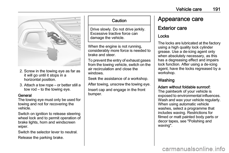
2. Screw in the towing eye as far asit will go until it stops in a
horizontal position.
3. Attach a tow rope – or better still a
tow rod – to the towing eye.
General
The towing eye must only be used for
towing and not for recovering the
vehicle.
Switch on ignition to release steering
wheel lock and to permit operation of
brake lights, horn and windscreen
wiper.
Switch the selector lever to neutral.
Release the parking brake.Caution
Drive slowly. Do not drive jerkily.
Excessive tractive force can
damage the vehicle.
When the engine is not running,
considerably more force is needed to
brake and steer.
To prevent the entry of exhaust gases from the towing vehicle, switch on the
air recirculation and close the
windows.
Seek the assistance of a workshop.
After towing, unscrew the towing eye.
Insert cap and engage in the front
bumper.
Appearance care
Exterior care
Locks The locks are lubricated at the factoryusing a high quality lock cylinder
grease. Use a de-icing agent only
when absolutely necessary, as this has a degreasing effect and impairs
lock function. After using a de-icing
agent, have the locks regreased by a
workshop.
WashingAdam without foldable sunroof:
The paintwork of your vehicle is
exposed to environmental influences.
Wash and wax your vehicle regularly.
When using automatic vehicle
washes, select a programme that
includes waxing. Restrictions for
filmed or matt painted body parts or
decor tapes, see "Polishing and
waxing".
Page 219 of 223

217DDanger, Warnings and Cautions ...4
Daytime running lights ...............100
Declaration of conformity ............207
Door open .................................... 79
Doors ............................................ 24
Driver assistance systems ..........129
Driver Information Centre .............80
Driving hints ................................ 115
E Electric adjustment ......................26
Electrical system......................... 164
Electronic climate control system 109
Electronic Stability Control.......... 126
Electronic Stability Control and Traction Control system ............77
Electronic Stability Control off....... 77
End-of-life vehicle recovery .......149
Engine compartment fuse box ...165
Engine coolant ........................... 152
Engine coolant temperature gauge ....................................... 70
Engine data ............................... 203
Engine exhaust .......................... 121
Engine identification ...................199
Engine oil ...........151, 196, 200, 205
Engine oil pressure ......................78
Entry lighting .............................. 104
Event data recorders ..................212Exhaust filter ......................... 78, 121
Exit lighting ................................ 104
Exterior care .............................. 191
Exterior light ................................. 79
Exterior lighting ......................12, 98
Exterior mirrors ............................. 26
F First aid ......................................... 57
First aid kit ................................... 57
Fixed air vents ........................... 114
Folding mirrors ............................. 26
Front airbag system .....................42
Front seats.................................... 32
Front storage ................................ 52
Front turn lights .......................... 158
Fuel............................................. 142
Fuel for liquid gas operation .......144
Fuel for petrol engines ...............142
Fuel gauge ................................... 69 Fuel selector ................................ 69
Fuel tank ..................................... 205
Fuses ......................................... 164
G Gauges ......................................... 68
Gear shifting ................................. 77
Glass panel .................................. 30
Glovebox ..................................... 51H
Halogen headlights ....................155
Hand brake ......................... 123, 124
Hazard warning flashers ............100
Headlight flash ............................. 99
Headlight range adjustment ......100
Headlights..................................... 98
Headlights when driving abroad 100
Head restraint adjustment .............8
Head restraints ............................ 31
Heated mirrors ............................. 26
Heated rear window ..................... 29
Heated steering wheel .................61
Heating ........................................ 35
Heating and ventilation system . 106
High beam ............................. 79, 99
Hill start assist ........................... 125
Horn ....................................... 13, 62
I
Identification plate .....................199
Ignition switch positions .............116
Immobiliser ............................ 25, 79
Indicators ...................................... 68
Info Display ................................... 85
Information displays...................... 80
Instrument cluster ........................68
Instrument panel fuse box .........167
Instrument panel illumination control .................................... 102