light VAUXHALL ADAM 2019 Repair Manual
[x] Cancel search | Manufacturer: VAUXHALL, Model Year: 2019, Model line: ADAM, Model: VAUXHALL ADAM 2019Pages: 223, PDF Size: 6.54 MB
Page 168 of 223

166Vehicle careNo.Circuit1Rear carrier2Exterior mirror switch3Body control module4Foldable power sunroof5ABS6Daytime running light left / low
beam left7–8Power window switch9Vehicle battery sensor10Headlamp levelling / Ignition11Rear wiper12Window defog13Daytime running light right / low
beam right14Exterior mirror heating15–No.Circuit16Fuel pump module / LPG
module17Interior mirror / Voltage
converter18Engine control module19Fuel pump20–21Solenoid canister purge22–23Ignition coils / Injectors24Washer system25Ambient light sensor / Rain light sensor26Engine sensors27Engine management28Engine control module / LPG
module29Engine control module30–No.Circuit31Left highbeam32Right highbeam33Engine control module34Horn35Air conditioning compressor
clutch36–
Page 171 of 223

Vehicle care169No.Circuit35–36–37Rear wiper38Cigarette lighter39Inductive charging40–Vehicle tools
Tools
Vehicles without spare wheel
Some tools and the towing eye are
located in a tool box in the load
compartment below the floor cover.
On version with storage box, remove
box first 3 54.
On versions with rear carrier system
or liquid gas engine, the tools are
located together with the towing eye,
fixed with a strap at the left sidewall in
the load compartment.
Page 176 of 223

174Vehicle careilluminates. For the further three
tyres, the system remains
operational.
The use of commercially-available liquid tyre repair kits can impair the
function of the system. Factory-
approved repair kits can be used.
Operating electronic devices or being close to facilities using similar wave
frequencies could disrupt the tyre
pressure monitoring system.
Each time the tyres are replaced, tyre
pressure monitoring system sensors
must be dismounted and serviced. For the screwed sensor; replace
valve core and sealing ring. For the
clipped sensor; replace complete
valve stem.
Vehicle loading status
Adjust tyre pressure to load condition according to the tyre information labelor tyre pressure chart 3 206, and
select the appropriate setting in the menu Tyre Load in the Driver
Information Centre, Vehicle
Information Menu 3 80 . This setting is
the reference for the tyre pressure
warnings.The Tyre Load menu only appears if
the vehicle is at a standstill and the parking brake is applied. On vehicles
with automatic transmission the
selector lever has to be in P.
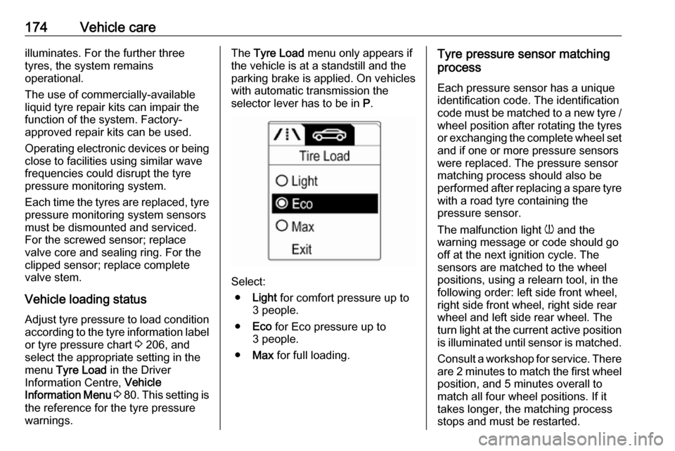
Select:
● Light for comfort pressure up to
3 people.
● Eco for Eco pressure up to
3 people.
● Max for full loading.
Tyre pressure sensor matching
process
Each pressure sensor has a unique
identification code. The identification
code must be matched to a new tyre /
wheel position after rotating the tyres
or exchanging the complete wheel set and if one or more pressure sensors
were replaced. The pressure sensor
matching process should also be
performed after replacing a spare tyre
with a road tyre containing the
pressure sensor.
The malfunction light w and the
warning message or code should go
off at the next ignition cycle. The
sensors are matched to the wheel
positions, using a relearn tool, in the following order: left side front wheel,
right side front wheel, right side rear
wheel and left side rear wheel. The
turn light at the current active position
is illuminated until sensor is matched.
Consult a workshop for service. There are 2 minutes to match the first wheelposition, and 5 minutes overall to
match all four wheel positions. If it
takes longer, the matching process
stops and must be restarted.
Page 181 of 223

Vehicle care179
6.Unscrew valve cap from defective
tyre.
7. Screw the filler hose to the tyre valve.
8. The switch on the compressor must be set to J.
9. Connect the compressor plug to the power outlet or cigarette
lighter socket.
To avoid discharging the battery,
we recommend running the
engine.10. Set the rocker switch on the compressor to I. The tyre is filled
with sealant.
11. The compressor pressure gauge briefly indicates up to 6 bar whilstthe sealant bottle is emptying
(approx. 30 seconds). Then the
pressure starts to drop.
12. All of the sealant is pumped into the tyre. Then the tyre is inflated.
13. The prescribed tyre pressure should be obtained within 10 min.
Tyre pressure 3 206.
When the correct pressure is
obtained, switch off the
compressor.
If the prescribed tyre pressure is
not obtained within 10 min,
remove the tyre repair kit. Move
the vehicle one tyre rotation.
Reattach the tyre repair kit and
continue the filling procedure for
10 min. If the prescribed tyre
pressure is still not obtained, the
tyre is too badly damaged. Seek
the assistance of a workshop.
Drain excess tyre pressure with
the button over the pressure indicator.
Page 183 of 223

Vehicle care181The adapters possibly supplied can
be used to pump up other items e.g.
footballs, air mattresses, inflatable
dinghies etc. They can be located on the underside of the compressor. To
remove, screw on compressor air
hose and withdraw adapter.
Wheel changing
Make the following preparations and
observe the following information:
● Park the vehicle on a level, firm and non-skid surface. The front
wheels must be in the straight- ahead position.
● Apply the parking brake and engage first gear or reverse gear.
● If the ground on which the vehicle
is standing is soft, a solid board
(max. 1 cm thick) should be
placed under the jack.
● Take heavy objects out of the vehicle before jacking up.
● No people or animals may be in the vehicle when it is jacked-up.
● Never crawl under a jacked-up vehicle.●Do not start the vehicle when it is
raised on the jack.
● Before screwing in the wheel bolts, clean them and lightly coat
the taper of each wheel bolt with
commercially available grease.9 Warning
Do not grease the thread of the
wheel bolt.
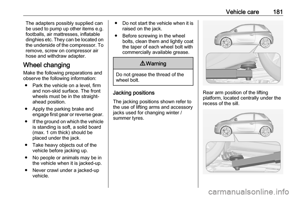
Jacking positions
The jacking positions shown refer to the use of lifting arms and accessory
jacks used for changing winter /
summer tyres.Rear arm position of the lifting
platform, located centrally under the
recess of the sill.
Page 184 of 223

182Vehicle careFront arm position of the lifting
platform at the underbody.
Spare wheel The spare wheel can be classified as
a temporary spare wheel depending
on the size compared to the other
mounted wheels and country
regulations. In this case a permissible maximum speed applies, even
though no label at the spare wheel
indicates this.
Only mount one temporary spare
wheel. Do not drive faster than
50 mph. Take curves slowly. Do not
use for a long period of time.Caution
The use of a spare wheel that is smaller than the other wheels or in combination with winter tyres
could affect driveability. Have the defective tyre replaced as soon as
possible.
The spare wheel is located in a holder
beneath the vehicle floor.
To remove:
1. Open the load compartment floor 3 55.
Remove storage box if equipped
3 54.
2. Remove the wheel wrench from the tool box.
3. Fit the wheel wrench on the hexagon bolt near the tool box
and turn it anticlockwise until a
resistance is noticeable.
4. Lift the spare wheel holder slightly
by hand and unhook the catch.
5. Lower the spare wheel holder.
Page 185 of 223

Vehicle care1836.Lift the spare wheel holder slightly
by hand and detach the safety
cable.
7. Lower holder all the way and remove spare wheel.
8. Change the wheel 3 181.
The damaged wheel must be
secured in the load compartment,
see below.
9. Lift the empty spare wheel holder and insert the safety cable.
10. Lift the spare wheel holder farther
and engage in catch. The open
side of the catch must point in the direction of travel.
11. Close the empty spare wheel holder by turning the hexagon boltclockwise successively using the
wheel wrench.
12. Close the load compartment floor.
Fitting the spare wheel
Make the following preparations and
observe the following information:
● Park the vehicle on a level, firm and non-skid surface. The front
wheels must be in the straight-
ahead position.
● Apply the parking brake and engage first gear or reverse gear.
● Remove the spare wheel.
● Never change more than one wheel at once.
● Use the jack only to change wheels in case of puncture, not
for seasonal winter or summer
tyre change.
● The jack is maintenance-free.
● If the ground on which the vehicle
is standing is soft, a solid board
(max. 1 cm thick) should be
placed under the jack.● Take heavy objects out of the vehicle before jacking up.
● No people or animals may be in the vehicle when it is jacked-up.
● Never crawl under a jacked-up vehicle.
● Do not start the vehicle when it is
raised on the jack.
● Before screwing in the wheel bolts, clean them and lightly coat
the taper of each wheel bolt with
commercially available grease.9 Warning
Do not grease the thread of the
wheel bolt.
1. Steel wheels
Pull off the wheel cover.
Alloy wheels with bolt caps Disengage wheel bolt caps with a
screwdriver and remove. To
protect the wheel, place a soft
cloth between the screwdriver
and the alloy wheel.
Alloy wheels with centre cap
Page 191 of 223

Vehicle care189● Apply the parking brake,transmission in neutral.
● Open the positive terminal protection caps of both vehicle
batteries.
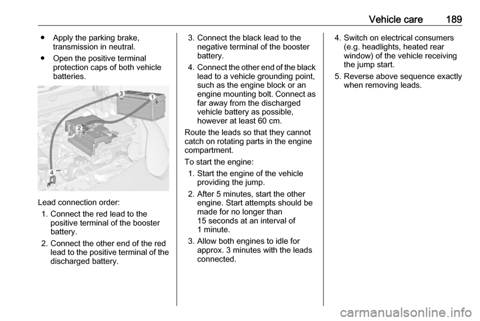
Lead connection order:
1. Connect the red lead to the positive terminal of the booster
battery.
2. Connect the other end of the red lead to the positive terminal of the
discharged battery.
3. Connect the black lead to the negative terminal of the booster
battery.
4. Connect the other end of the black
lead to a vehicle grounding point,
such as the engine block or an
engine mounting bolt. Connect as far away from the discharged
vehicle battery as possible,
however at least 60 cm.
Route the leads so that they cannot
catch on rotating parts in the engine
compartment.
To start the engine: 1. Start the engine of the vehicle providing the jump.
2. After 5 minutes, start the other engine. Start attempts should be
made for no longer than
15 seconds at an interval of
1 minute.
3. Allow both engines to idle for approx. 3 minutes with the leads
connected.4. Switch on electrical consumers (e.g. headlights, heated rear
window) of the vehicle receiving
the jump start.
5. Reverse above sequence exactly when removing leads.
Page 193 of 223

Vehicle care191
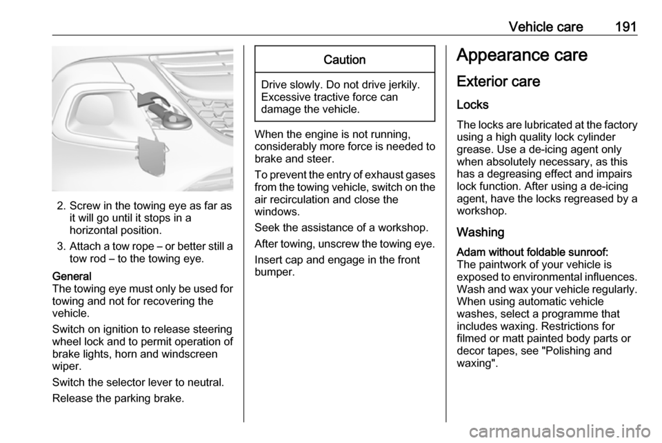
2. Screw in the towing eye as far asit will go until it stops in a
horizontal position.
3. Attach a tow rope – or better still a
tow rod – to the towing eye.
General
The towing eye must only be used for
towing and not for recovering the
vehicle.
Switch on ignition to release steering
wheel lock and to permit operation of
brake lights, horn and windscreen
wiper.
Switch the selector lever to neutral.
Release the parking brake.Caution
Drive slowly. Do not drive jerkily.
Excessive tractive force can
damage the vehicle.
When the engine is not running,
considerably more force is needed to
brake and steer.
To prevent the entry of exhaust gases from the towing vehicle, switch on the
air recirculation and close the
windows.
Seek the assistance of a workshop.
After towing, unscrew the towing eye.
Insert cap and engage in the front
bumper.
Appearance care
Exterior care
Locks The locks are lubricated at the factoryusing a high quality lock cylinder
grease. Use a de-icing agent only
when absolutely necessary, as this has a degreasing effect and impairs
lock function. After using a de-icing
agent, have the locks regreased by a
workshop.
WashingAdam without foldable sunroof:
The paintwork of your vehicle is
exposed to environmental influences.
Wash and wax your vehicle regularly.
When using automatic vehicle
washes, select a programme that
includes waxing. Restrictions for
filmed or matt painted body parts or
decor tapes, see "Polishing and
waxing".
Page 195 of 223

Vehicle care193Exterior lights
Headlight and other light covers are
made of plastic. Do not use any
abrasive or caustic agents, do not use an ice scraper, and do not clean them
dry.
Polishing and waxing
Wax painted parts of the vehicle
regularly (at the latest when water no longer beads). Otherwise, the
paintwork will dry out.
The foldable sunroof must not be
polished or waxed. When using
automatic car washes, select a
programme without wax additives.
Polishing is necessary only if the paint
has become dull or if solid deposits
have become attached to it.
Paintwork polish with silicone forms a
protective film, making waxing
unnecessary.
Unpainted plastic body parts must not
be treated with wax or polishing
agents.
Matt filmed body parts or decor tapes must not be polished, to avoid
gleaming. Do not use hot waxprogrammes in automatic car washes if the vehicle is equipped with theseparts.
Matt painted decor parts, e.g. mirror housing cover, must not be polished.
Otherwise these parts would become agleam or the colour would be
dissolved.
Windows and windscreen wiper
blades
Switch off wipers before handling in
their areas.
Use a soft lint-free cloth or chamois leather together with window cleaner
and insect remover.
When cleaning the rear window from
inside, always wipe in parallel to the
heating element to prevent damage.
For mechanical removal of ice, use a
sharp-edged ice scraper. Press the
scraper firmly against the glass so
that no dirt can get under it and
scratch the glass.
Clean smearing wiper blades with a
soft cloth and window cleaner.Glass panel
Never clean with solvents or abrasive
agents, fuels, aggressive media
(e.g. paint cleaner, acetone-
containing solutions etc.), acidic or
highly alkaline media or abrasive
pads. Do not apply wax or polishing
agents to the glass panel.
Wheels and tyres
Do not use high-pressure jet
cleaners.
Clean rims with a pH-neutral wheel
cleaner.
Rims are painted and can be treated
with the same agents as the body.
Paintwork damage
Rectify minor paintwork damage with a touch-up pen before rust forms.
Have more extensive damage or rust areas repaired by a workshop.
Underbody Some areas of the vehicle underbody
have a PVC undercoating while other
critical areas have a durable
protective wax coating.