lock VAUXHALL ANTARA 2015 Workshop Manual
[x] Cancel search | Manufacturer: VAUXHALL, Model Year: 2015, Model line: ANTARA, Model: VAUXHALL ANTARA 2015Pages: 223, PDF Size: 6.07 MB
Page 176 of 223

174Vehicle care
FuseCircuitAMPAmplifierAPO JACK
(CONSOLE)Power outlet
(centre console)APO JACK
(REAR CARGO)Power outlet
(load compart‐
ment)AWD/VENTAll-wheel drive,
ventilationBCM (CTSY)Courtesy lightsBCM (DIMMER)Instrument illu‐
minationBCM (INT LIGHT
TRLR FOG)Interior lights,
trailer fog lightBCM (PRK/TRN)Parking lights,
turn signalsBCM (STOP)Brake lightsBCM (TRN SIG)Turn signalsBCM (VBATT)Battery voltageFuseCircuitCIMCommunica‐
tions Integration
ModuleCLSTRInstrument
clusterDRLDaytime running
lightsDR/LCKDriver door lockDRVR PWR
SEATDriver power
seatDRV/PWR
WNDWDriver power
windowF/DOOR LOCKFuel filler flapFRT WSRFront washerFSCMFuel systemFSCM/VENT SOLFuel system,
vent solenoidHEATING MAT
SWHeating mat
switchHTD SEAT PWRSeat heatingFuseCircuitHVAC BLWRClimate control,
air conditioning
fanIPCInstrument panel clusterISRVM/RCMInterior mirror,
remote compass moduleKEY CAPTUREKey captureL/GATETailgateLOGISTIC MODELogistic modeOSRVMExterior mirrorsPASS PWR
WNDWPassenger
power windowPWR DIODEPower diodePWR MODINGPower modingRADIORadioRR FOGHeated rear
window
Page 178 of 223

176Vehicle care
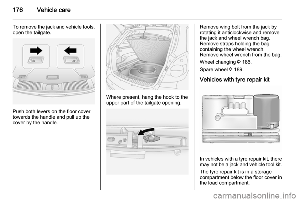
To remove the jack and vehicle tools,open the tailgate.
Push both levers on the floor cover
towards the handle and pull up the
cover by the handle.
Where present, hang the hook to the
upper part of the tailgate opening.
Remove wing bolt from the jack by
rotating it anticlockwise and remove
the jack and wheel wrench bag.
Remove straps holding the bag
containing the wheel wrench.
Remove wheel wrench from the bag.
Wheel changing 3 186.
Spare wheel 3 189.
Vehicles with tyre repair kit
In vehicles with a tyre repair kit, there may not be a jack and vehicle tool kit.
The tyre repair kit is in a storage
compartment below the floor cover in the load compartment.
Page 185 of 223

Vehicle care1839Warning
Use of unsuitable tyres or wheel
covers could lead to sudden
pressure loss and thereby
accidents.
Tyre chains
Tyre chains are only permitted on the
front wheels.
They must be fitted to the tyres
symmetrically in order to achieve a
concentric fit.
Always use fine mesh chains that add no more than 15 mm to the tyre tread
and the inboard sides (including chain lock).9 Warning
Damage may lead to tyre blowout.
Tyre chains are permitted only on
16 inch wheels. We recommend you consult a workshop.
If the use of tyre chains is required
after suffering a flat front tyre, fit the
temporary spare wheel on the rear
axle and transfer one of the rear
wheels to the front axle.
General
The use of tyre chains is not permitted on the temporary spare wheel.
Tyre repair kit
Minor damage to the tyre tread or
sidewall can be repaired with the tyre
repair kit.
Do not remove foreign bodies from
the tyres.
Tyre damage exceeding 4 mm or that
is at the tyre's sidewall near the rim
cannot be repaired with the tyre repair kit.
In vehicles with a tyre repair kit, there may not be a jack and vehicle tool kit.
Vehicle tools 3 175.
Temporary spare wheel 3 189.9 Warning
Do not drive faster than 50 mph.
Do not use for a lengthy period.
Steering and handling may be
affected.
If you have a flat tyre:
Apply the electrical parking brake
3 137 and engage first gear, reverse
gear or P.
The tyre repair kit is in a storage
compartment below the floor cover in the load compartment.
To remove the tyre repair kit, open the
tailgate.
Page 186 of 223

184Vehicle care
Pull the floor cover handle upwards
3 69.
Vehicle tools 3 175.Caution
Do not allow objects to protrude
above the top of the rear floor
storage compartment, to avoid
damage to the storage area and
the load compartment floor.
1. Release the sealant filler hose 1
and the power plug 2.
2. Unscrew valve cap from defective
tyre.
Screw the sealant filler hose onto
the tyre valve.
3. Connect the power plug to the power outlet. Unplug all items
from other power outlets.
4. Switch on ignition. To avoid discharging the battery, werecommend running the engine.
5. Turn the selector switch anticlockwise to the sealant +
air position.
6. Press the on/off button to turn the
tyre repair kit on. The tyre is filled
with sealant.
The pressure gauge briefly shows a high pressure while the sealant
canister is emptying. Then the
pressure starts to drop.
All of the sealant is pumped into
the tyre. Then the tyre is inflated.
7. Inflate the tyre to the recommended inflation pressure
using the pressure gauge. The
prescribed tyre pressure should
be obtained within 10 minutes
3 210 . When the correct pressure
Page 188 of 223

186Vehicle care
13.Turn the selector switch clockwise
to the air only position. Switch on
the compressor to inflate the tyre
with air only.
Notice
The driving characteristic of the
repaired tyre is severely affected,
therefore have this tyre replaced.
If unusual noise is heard or the
compressor becomes hot, turn
compressor off for at least
30 minutes.
Note the expiry date of the kit. After
this date its sealing capability is no
longer guaranteed. Pay attention to
storage information on sealant
canister.
Replace the used sealant canister.
To remove sealant canister, release sealant filler hose and air hose, slide
canister out of housing and unscrew hose from canister. Dispose of thecanister as prescribed by applicable
laws.
The accessory adapter supplied can
be used to pump up other items
e.g. footballs, air mattresses,
inflatable dinghies etc. The adapter
is located on the underside of the
tyre repair kit.
Wheel changing Some vehicles are equipped with a
tyre repair kit instead of a spare wheel 3 183.Make the following preparations and
observe the following information:
■ Park the vehicle on a level, firm and
non-slippery surface. The frontwheels must be in the straight-
ahead position.
■ Apply the electrical parking brake 3 137 and engage first gear,
reverse gear or P.
■ Remove the spare wheel 3 189.
■ Never change more than one wheel
at a time.
■ Block wheel diagonally opposite the wheel to be changed, by placing
wedge blocks or equivalent in front
and behind the wheel.
■ Use the jack only to change wheels
in case of puncture, not for
seasonal winter or summer tyre
changes.
■ Never exceed jack maximum working load (900 kg).
■ If the ground on which the vehicle is standing is soft, a solid board
(max. 1 cm thick) should be placed
under the jack.
Page 189 of 223

Vehicle care187
■ Do not raise the vehicle more thanis necessary to change a wheel.
■ No people or animals may be in the
vehicle when it is jacked-up.
■ Never crawl under a jacked-up vehicle.
■ Do not start the engine when it is raised on the jack.
■ Clean wheel nuts and thread before
mounting the wheel.9 Warning
Do not grease wheel bolt, wheel
nut and wheel nut cone.
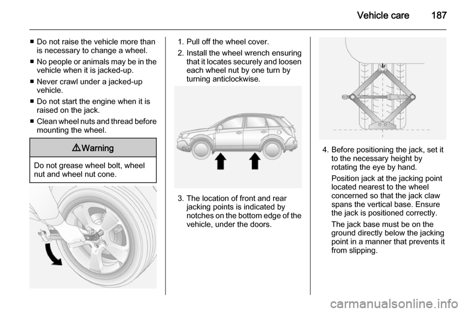
1. Pull off the wheel cover.
2. Install the wheel wrench ensuring that it locates securely and loosen
each wheel nut by one turn by
turning anticlockwise.
3. The location of front and rear jacking points is indicated by
notches on the bottom edge of the
vehicle, under the doors.
4. Before positioning the jack, set it to the necessary height by
rotating the eye by hand.
Position jack at the jacking point
located nearest to the wheel
concerned so that the jack claw
spans the vertical base. Ensure
the jack is positioned correctly.
The jack base must be on the
ground directly below the jacking
point in a manner that prevents it
from slipping.
Page 190 of 223

188Vehicle care
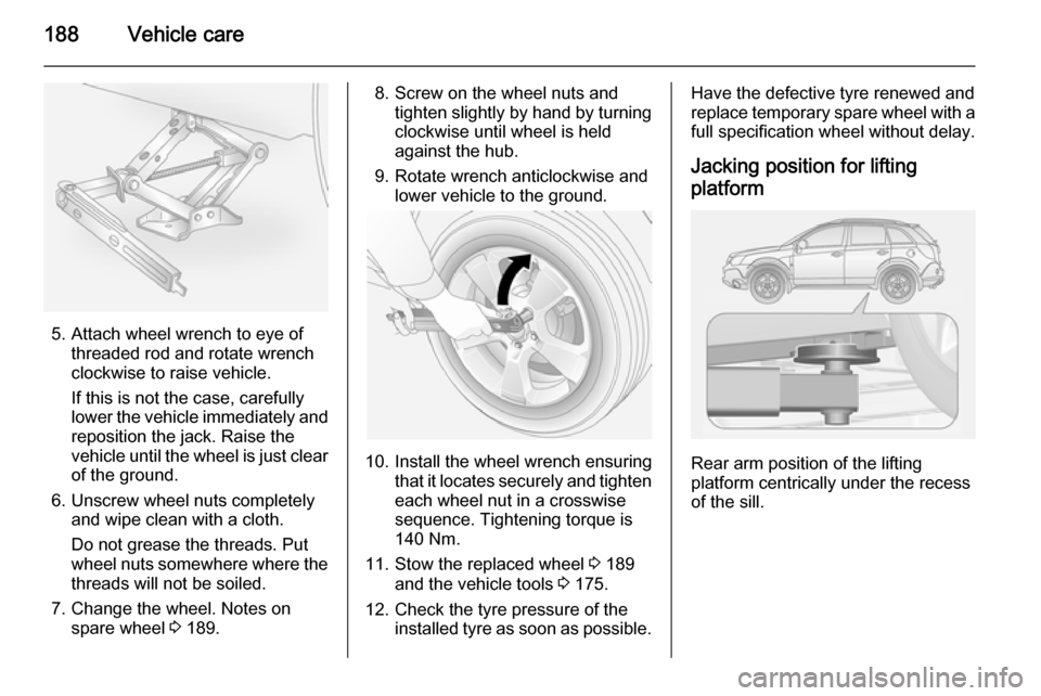
5. Attach wheel wrench to eye ofthreaded rod and rotate wrench
clockwise to raise vehicle.
If this is not the case, carefully
lower the vehicle immediately and
reposition the jack. Raise the
vehicle until the wheel is just clear of the ground.
6. Unscrew wheel nuts completely and wipe clean with a cloth.
Do not grease the threads. Put
wheel nuts somewhere where the threads will not be soiled.
7. Change the wheel. Notes on spare wheel 3 189.
8. Screw on the wheel nuts and
tighten slightly by hand by turning
clockwise until wheel is held
against the hub.
9. Rotate wrench anticlockwise and lower vehicle to the ground.
10. Install the wheel wrench ensuring that it locates securely and tighten
each wheel nut in a crosswise
sequence. Tightening torque is
140 Nm.
11. Stow the replaced wheel 3 189
and the vehicle tools 3 175.
12. Check the tyre pressure of the installed tyre as soon as possible.
Have the defective tyre renewed and
replace temporary spare wheel with a
full specification wheel without delay.
Jacking position for lifting platform
Rear arm position of the lifting
platform centrically under the recess
of the sill.
Page 191 of 223

Vehicle care189
Front arm position of the lifting
platform centrically under the recess
of the sill.
Spare wheel
Temporary spare wheel
Some vehicles are equipped with a
tyre repair kit instead of a spare
wheel.
The temporary spare wheel is
designed for use on your vehicle only.
If mounting a spare wheel which is
different from the other wheels, this
wheel might be classified as a
temporary spare wheel and the
corresponding speed limits apply,
even though no label indicates this.
Seek the assistance of a workshop to
check the applicable speed limit.
Use of the temporary spare wheel
could affect driveability, particularly if
using winter tyres. Have the defective
tyre renewed as soon as possible and
have the wheel balanced and fitted to the vehicle.Caution
The use of a spare wheel that issmaller than the other wheels or in
combination with winter tyres
could affect driveability. Have the defective tyre replaced as soon as
possible.The temporary spare wheel is located in the load compartment below the
floor cover and is secured with a
screw-in retainer.
Push both levers on the floor cover
towards the handle and pull up the
cover by the handle. Hang the hook
to the upper part of the tailgate
opening.
Vehicle tools 3 175.
Remove the retainer by rotating it
anticlockwise and remove temporary
spare wheel from the spare wheel
well.
Page 193 of 223

Vehicle care191
■ A discharged battery can alreadyfreeze at a temperature of 0 °C.
Defrost the frozen battery before
connecting jump leads.
■ Wear eye protection and protective
clothing when handling a battery.
■ Use a booster battery with the same voltage (12 Volts). Its
capacity (Ah) must not be much less than that of the discharged
battery.
■ Use jump leads with insulated terminals and a cross section of at
least 16 mm 2
(25 mm 2
for diesel
engines).
■ Do not disconnect the discharged battery from the vehicle.
■ Switch off all unnecessary electrical
consumers. The Infotainment
system may be damaged if
switched on while jump starting.
■ Do not lean over the battery during jump starting.
■ Do not allow the terminals of one lead to touch those of the other
lead.■ The vehicles must not come into contact with each other during the
jump starting process.
■ Apply the electrical parking brake 3 137, transmission in neutral,
automatic transmission in P.
■ Open the positive terminal protection caps of both batteries.
Lead connection order:
1. Connect the red lead to the positive terminal 1 of the booster
battery.
2. Connect the other end of the red lead to the positive terminal 2 of
the discharged battery.
3. Connect the black lead to the negative terminal 3 of the booster
battery.
4. Connect the other end of the black
lead to a vehicle grounding point,
such as the engine block 4 or an
engine mounting bolt. Connect as far away from the discharged
battery as possible, however at
least 60 cm.
Route the leads so that they cannot
catch on rotating parts in the engine
compartment.
To start the engine: 1. Start the engine of the vehicle providing the jump start.
2. After 5 minutes, start the other engine. Start attempts should be
made for no longer than
15 seconds at an interval of
1 minute.
3. Allow both engines to idle for approx. 3 minutes with the leads
connected.
Page 194 of 223

192Vehicle care
4. Switch on electrical consumers(e.g. headlights, heated rear
window) of the vehicle receiving
the jump start.
5. Operate discharged vehicle for approx. 20 minutes to allow for
adequate battery recharging.
6. Reverse above sequence exactly when removing leads.Towing
Towing the vehicle
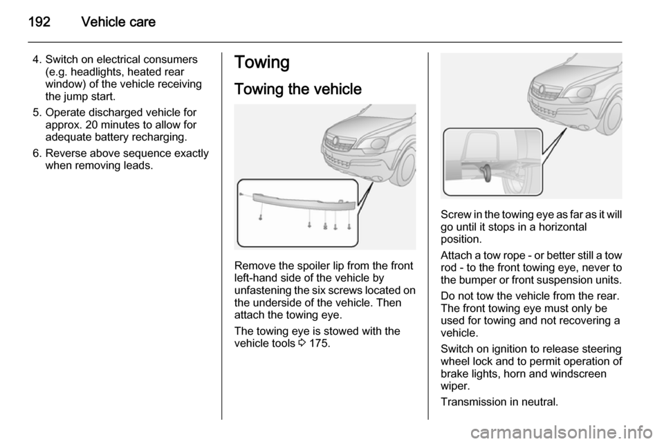
Remove the spoiler lip from the front
left-hand side of the vehicle by
unfastening the six screws located on the underside of the vehicle. Then
attach the towing eye.
The towing eye is stowed with the
vehicle tools 3 175.
Screw in the towing eye as far as it will
go until it stops in a horizontal
position.
Attach a tow rope - or better still a tow
rod - to the front towing eye, never to
the bumper or front suspension units.
Do not tow the vehicle from the rear.
The front towing eye must only be
used for towing and not recovering a
vehicle.
Switch on ignition to release steering wheel lock and to permit operation of
brake lights, horn and windscreen
wiper.
Transmission in neutral.