stop start VAUXHALL ASTRA J 2015.75 Owner's Guide
[x] Cancel search | Manufacturer: VAUXHALL, Model Year: 2015.75, Model line: ASTRA J, Model: VAUXHALL ASTRA J 2015.75Pages: 337, PDF Size: 10.17 MB
Page 171 of 337

Driving and operating169
The selected gear is indicated in the
instrument cluster.
If a higher gear is selected when
vehicle speed is too low, or a lower
gear when vehicle speed is too high,
the shift is not executed. This can
cause a message in the Driver
Information Centre (DIC).
In manual mode, no automatic
shifting to a higher gear takes place
at high engine revolutions.
Electronic driving
programmes ■ Following a cold start, the operating
temperature programme increasesengine speed to quickly bring the
catalytic converter to the required
temperature.
■ The automatic neutral shift function
automatically shifts to idling when
the vehicle is stopped with a
forward gear engaged and the
brake pedal is pressed.■ When SPORT mode is engaged, the vehicle shifts at higher engine
speeds (unless cruise control is
on). SPORT mode 3 176.
■ Special programmes automatically adapt the shifting points when
driving up inclines or down hills.
■ When starting off in snowy or icy conditions or on other slippery
surfaces, the electronic
transmission control selects a
higher gear automatically.
Kickdown If the accelerator pedal is pressed
down completely in automatic mode, the transmission shifts to a lower gear
depending on engine speed.
Fault
In the event of a fault, control indicator g illuminates. Additionally, a code
number or a vehicle message is
displayed in the Driver Information
Centre (DIC). Vehicle messages
3 125.The transmission no longer shifts
automatically. Continued travel ispossible with manual shifting.
Only the highest gear is available.
Depending on the fault, 2nd gear may also be available in manual mode.
Shift only when vehicle is at a
standstill.
Have the cause of the fault remedied
by a workshop.
Interruption of power
supply
In the event of an interruption of
power supply, the selector lever
cannot be moved out of the P
position. The ignition key cannot be
removed from the ignition switch.
If the vehicle battery is discharged,
start the vehicle using jump leads
3 277.
If the vehicle battery is not the cause
of the fault, release the selector lever.
1. Apply the parking brake.
Page 176 of 337
174Driving and operatingHill start assistThe system helps prevent unintendedmovement when driving away on
inclines.
When releasing the foot brake after
stopping on an incline, the brakes
remain on for a further two seconds.
The brakes release automatically as
soon as the vehicle begins to
accelerate.
The hill start assist is not active during
an Autostop.Ride control systems
Traction Control system
The Traction Control system (TC) is a component of the Electronic Stability
Control (ESC) 3 175.
TC improves driving stability when
necessary, regardless of the type of
road surface or tyre grip, by
preventing the drive wheels from spinning.
As soon as the drive wheels starts to
spin, engine output is reduced and
the wheel spinning the most is braked
individually. This considerably
improves the driving stability of the
vehicle on slippery road surfaces.
TC is operational after each engine
start as soon as the control indicator
b extinguishes.
When TC operates b flashes.9 Warning
Do not let this special safety
feature tempt you into taking risks
when driving.
Adapt speed to the road
conditions.
Control indicator b 3 115.
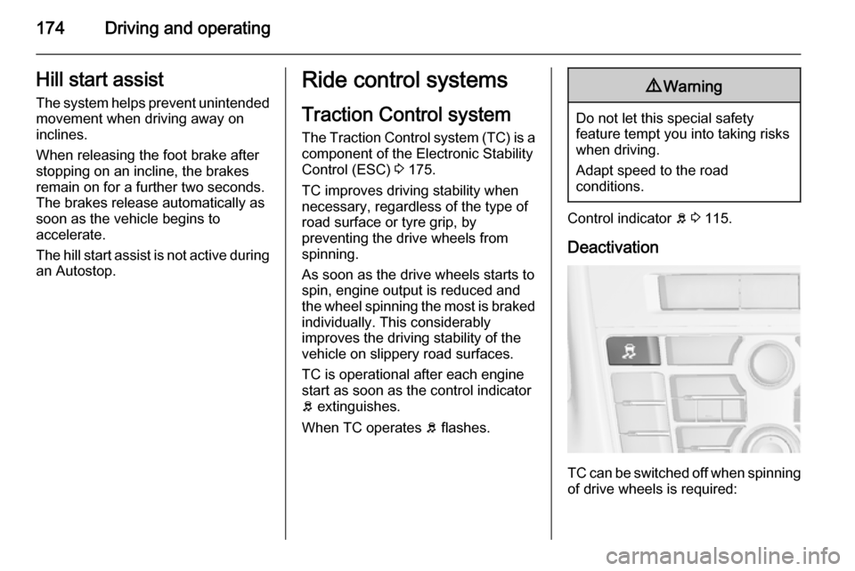
Deactivation
TC can be switched off when spinning of drive wheels is required:
Page 201 of 337
Driving and operating199
Button D and operation logic
Advanced parking assist and front-
rear parking assist (see previous
description) are both operated by
pressing D.
Short press of D deactivates or
activates the front parking assist.
Long press of D (approx.
one second) activates or deactivates the advanced parking assist.
Button logic operates the systems by
pressing as following:
■ Front-rear parking assist is active: short press deactivates front-rear
parking assist.
■ Front-rear parking assist is active: long press activates advanced
parking assist if a forward gear is engaged.
■ Advanced parking assist is active: short press activates front-rear
parking assist.■ Advanced parking assist is active: long press deactivates advanced
parking assist.
■ Advanced parking assist and front- rear parking assist are active: shortpress deactivates both systems.
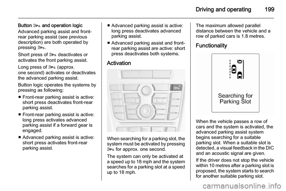
Activation
When searching for a parking slot, the
system must be activated by pressing D for approx. one second.
The system can only be activated at
a speed up to 18 mph and the system
searches for a parking slot at a speed up to 18 mph.
The maximum allowed parallel
distance between the vehicle and a
row of parked cars is 1.8 metres.
Functionality
When the vehicle passes a row of
cars and the system is activated, the
advanced parking assist system
begins searching for a suitable
parking slot. When a suitable slot is
detected, a visual feedback in the DIC
and an acoustic signal are given.
If the driver does not stop the vehicle within 10 metres after a parking slot is proposed, the system starts to search
for another suitable parking slot.
Page 227 of 337
Vehicle care2259Danger
The ignition system and Xenon
headlights use extremely high
voltage. Do not touch.
Bonnet
Opening
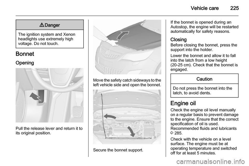
Pull the release lever and return it to
its original position.
Move the safety catch sideways to the left vehicle side and open the bonnet.
Secure the bonnet support.
If the bonnet is opened during an
Autostop, the engine will be restarted automatically for safety reasons.
Closing Before closing the bonnet, press the
support into the holder.
Lower the bonnet and allow it to fall
into the latch from a low height
(20-25 cm). Check that the bonnet is engaged.Caution
Do not press the bonnet into the
latch, to avoid dents.
Engine oil
Check the engine oil level manuallyon a regular basis to prevent damage
to the engine. Ensure that the correct specification of oil is used.
Recommended fluids and lubricants
3 285.
Check with the vehicle on a level
surface. The engine must be at
operating temperature and switched
off for at least 5 minutes.
Page 230 of 337
228Vehicle careWasher fluid
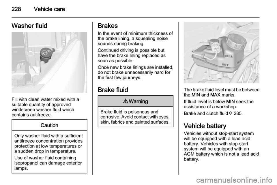
Fill with clean water mixed with a
suitable quantity of approved
windscreen washer fluid which
contains antifreeze.
Caution
Only washer fluid with a sufficient
antifreeze concentration provides
protection at low temperatures or
a sudden drop in temperature.
Use of washer fluid containing
isopropanol can damage exterior
lamps.
Brakes
In the event of minimum thickness ofthe brake lining, a squealing noise
sounds during braking.
Continued driving is possible but
have the brake lining replaced as
soon as possible.
Once new brake linings are installed,
do not brake unnecessarily hard for
the first few journeys.
Brake fluid9 Warning
Brake fluid is poisonous and
corrosive. Avoid contact with eyes, skin, fabrics and painted surfaces.
The brake fluid level must be betweenthe MIN and MAX marks.
If fluid level is below MIN seek the
assistance of a workshop.
Brake and clutch fluid 3 285.
Vehicle battery Vehicles without stop-start system
will be equipped with a lead acid
battery. Vehicles with stop-start
system will be equipped with an
AGM battery which is not a lead acid
battery.
Page 231 of 337
Vehicle care229
The vehicle battery is maintenance-
free provided that the driving profile
allows sufficient charging of the
battery. Short-distance-driving and
frequent engine starts can discharge
the battery. Avoid the use of
unnecessary electrical consumers.
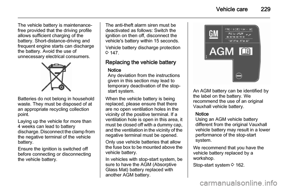
Batteries do not belong in household
waste. They must be disposed of at
an appropriate recycling collection
point.
Laying up the vehicle for more than
4 weeks can lead to battery
discharge. Disconnect the clamp from the negative terminal of the vehicle
battery.
Ensure the ignition is switched off
before connecting or disconnecting
the vehicle battery.
The anti-theft alarm siren must be
deactivated as follows: Switch the ignition on then off, disconnect the
vehicle's battery within 15 seconds.
Vehicle battery discharge protection
3 147.
Replacing the vehicle battery Notice
Any deviation from the instructions
given in this section may lead to
temporary deactivation of the stop-
start system.
When the vehicle battery is being
replaced, please ensure that there
are no open ventilation holes in the
vicinity of the positive terminal. If a
ventilation hole is open in this area, it
must be closed off with a dummy cap, and the ventilation in the vicinity of the
negative terminal must be opened.
Only use vehicle batteries that allow
the fuse box to be mounted above the
vehicle battery.
In vehicles with stop-start system, be
sure to have the AGM (Absorptive
Glass Mat) battery replaced with
another AGM battery.
An AGM battery can be identified by
the label on the battery. We
recommend the use of an original
Vauxhall vehicle battery.
Notice
Using an AGM vehicle battery
different from the original Vauxhall
vehicle battery may result in a lower performance of the stop-start
system.
We recommend that you have the
vehicle battery replaced by a
workshop.
Stop-start system 3 162.
Page 232 of 337
230Vehicle care
Charging the vehicle battery9Warning
On vehicles with stop-start
system, ensure that the charging potential does not exceed
14.6 volts when using a battery
charger. Otherwise the vehicle
battery might be damaged.
Jump starting 3 277.
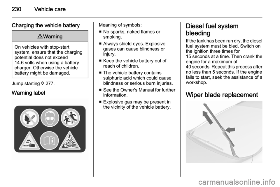
Warning label
Meaning of symbols: ■ No sparks, naked flames or smoking.
■ Always shield eyes. Explosive gases can cause blindness or
injury.
■ Keep the vehicle battery out of reach of children.
■ The vehicle battery contains sulphuric acid which could cause
blindness or serious burn injuries.
■ See the Owner's Manual for further
information.
■ Explosive gas may be present in the vicinity of the vehicle battery.Diesel fuel system
bleeding
If the tank has been run dry, the diesel
fuel system must be bled. Switch on
the ignition three times for
15 seconds at a time. Then crank the
engine for a maximum of
40 seconds. Repeat this process after
no less than 5 seconds. If the engine fails to start, seek the assistance of a
workshop.
Wiper blade replacement
Page 255 of 337

Vehicle care253
No.Circuit15Engine control module16Starter17Transmission control module18Heated rear window19Front power windows20Rear power windows21Rear electrical centre22Left high beam (Halogen)23Headlamp washer system24Right low beam (Xenon)25Left low beam (Xenon)26Front fog lights27Diesel fuel heating28Start stop system29Electric parking brake30ABS31Adaptive cruise controlNo.Circuit32Airbag33Adaptive forward lighting/Auto‐
matic light control34Exhaust gas recirculation35Exterior mirror/Rain sensor36Climate control37Canister vent solenoid38Vacuum pump39Central control module40Windscreen washer/Rear
window washer system41Right high beam (Halogen)42Radiator fan43Windscreen wiper44Windscreen wiper45Radiator fan46–No.Circuit47Horn48Radiator fan49Fuel pump50Headlamp levelling/Adaptive
forward lighting51Air shutter52Auxiliary heater/Diesel engine53Transmission control module/
Engine control module54Vacuum pump/Instrument
panel cluster/Heating ventila‐
tion/Air conditioning system
After having changed defective fuses,
close the fuse box cover and press
until it engages.
If the fuse box cover is not closed
correctly, malfunction may occur.
Page 265 of 337

Vehicle care263
performed after replacing a spare tyrewith a road tyre containing the TPMS
sensor.
The malfunction light and the warning
message or code should go off at the
next ignition cycle. The sensors are
matched to the tyre/wheel positions,
using a TPMS relearn tool, in the
following order: left side front tyre,
right side front tyre, right side rear tyre and left side rear tyre. The turn signal
light at the current active position is
illuminated until sensor is matched.
Consult your workshop for service or
to purchase a relearn tool. There are
two minutes to match the first tyre/
wheel position, and five minutes
overall to match all four tyre/wheel
positions. If it takes longer, the
matching process stops and must be
restarted.
The TPMS sensor matching process is:
1. Apply the parking brake; on vehicles with automatic
transmission set the selector lever
to P.
2. Turn the ignition on.3. Use MENU on the turn signal
lever to select the Vehicle
Information Menu in the DIC.
4. Turn the adjuster wheel to scroll to
the tyre pressure menu.
5. Press the SET/CLR button to
begin the sensor matching process. A message requesting
acceptance of the process should display.
6. Press the SET/CLR button again
to confirm the selection. The horn sounds twice to signal the
receiver is in relearn mode.
7. Start with the left side front tyre.
8. Place the relearn tool against the tyre sidewall, near the valve stem.
Then press the button to activate
the TPMS sensor. A horn chirp
confirms that the sensor
identification code has been
matched to this tyre and wheel
position.
9. Proceed to the right side front tyre,
and repeat the procedure in
Step 8.10. Proceed to the right side rear tyre,
and repeat the procedure in
Step 8.
11. Proceed to the left side rear tyre, and repeat the procedure in
Step 8. The horn sounds twice to
indicate the sensor identification
code has been matched to the left side rear tyre, and the TPMS
sensor matching process is no
longer active.
12. Turn off the ignition.
13. Set all four tyres to the recommended air pressure level
as indicated on the tyre pressure
label.
14. Ensure the tyre loading status is set according selected pressure
3 118.
Temperature dependency Tyre pressure depends on the
temperature of the tyre. During
driving, tyre temperature and
pressure increase.
Page 335 of 337

333
PParking ................................ 19, 164
Parking assist ............................ 195
Parking brake ............................ 172
Parking lights ............................. 144
Particulate filter ........................... 165
Performance .............................. 295
Performing work ........................224
Pollen filter ................................. 158
Power outlets ............................. 105
Power seat adjustment ................43
Power steering............................ 115
Power steering fluid ....................227
Power windows ............................ 32
Preheating ................................. 116
Puncture ..................................... 268
Q
Quickheat ................................... 157
R Radio Frequency Identification (RFID) .................................... 329
Radio remote control ...................21
Reading lights ............................ 146
Rear carrier system ......................63
Rear floor storage cover ..............88
Rear fog light ............................. 118
Rear fog lights ........................... 144
Rear seats .................................... 46Rear storage................................. 85
Rear view camera ...................... 204
Rear window wiper/washer ........ 103
Recommended fluids and lubricants ........................ 285, 289
Reduced engine power ..............117
Refuelling ................................... 213
Retained power off .....................160
Reversing lights .........................144
Ride control systems ..................174
Roof .............................................. 35
Roof load ...................................... 97
Roof rack ..................................... 96
S Safety belts ................................... 46
Safety net .................................... 92
Seat adjustment ....................... 7, 39
Seat belt ........................................ 9
Seat belt reminder .....................112
Seat belts ..................................... 46
Seat folding .................................. 42
Seat position ................................ 39
Selector lever ............................. 167
Service ............................... 158, 284
Service display .......................... 109
Service information ....................284
Service vehicle soon .................. 113
Side airbag system ......................50
Side blind spot alert ....................202Sidelights.................................... 136
Side turn signal lights ................248
Smartphone controller ................124
Spare wheel ............................... 272
Speed limiter............................... 181
Speedometer ............................. 107
Starting and operating ................160
Starting off ................................... 18
Starting the engine ....................160
Steering ...................................... 159
Steering wheel adjustment ....10, 99
Steering wheel controls ...............99
Stop-start system........................ 162
Storage ......................................... 59
Storage compartments .................59
Sunroof ........................................ 35
Sunvisor lights ........................... 146
Sun visors .................................... 34
Symbols ......................................... 4
T Tachometer ............................... 107
Tail lights ................................... 241
Three-point seat belt .................... 47
Tools .......................................... 257
Top-tether fastening eyes ............58
Tow bar....................................... 217
Towing ................................ 217, 278
Towing another vehicle .............279
Towing equipment .....................218