clock VAUXHALL ASTRA J 2016 Owner's Guide
[x] Cancel search | Manufacturer: VAUXHALL, Model Year: 2016, Model line: ASTRA J, Model: VAUXHALL ASTRA J 2016Pages: 341, PDF Size: 10.35 MB
Page 249 of 341

Vehicle care2474. Carefully withdraw tail lightassembly from recesses and
remove. Make sure that the cable duct remains in position.
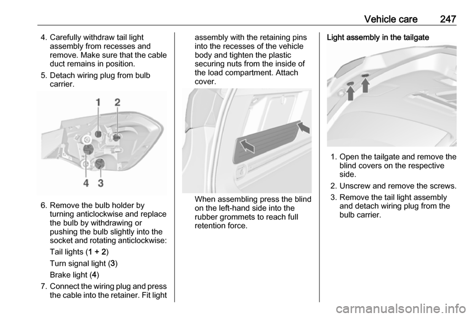
5. Detach wiring plug from bulb carrier.
6. Remove the bulb holder by turning anticlockwise and replace
the bulb by withdrawing or
pushing the bulb slightly into the
socket and rotating anticlockwise:
Tail lights ( 1 + 2)
Turn signal light ( 3)
Brake light ( 4)
7. Connect the wiring plug and press
the cable into the retainer. Fit light
assembly with the retaining pins
into the recesses of the vehicle
body and tighten the plastic
securing nuts from the inside of
the load compartment. Attach
cover.
When assembling press the blind
on the left-hand side into the
rubber grommets to reach full
retention force.
Light assembly in the tailgate
1. Open the tailgate and remove the
blind covers on the respective
side.
2. Unscrew and remove the screws. 3. Remove the tail light assembly and detach wiring plug from the
bulb carrier.
Page 250 of 341

248Vehicle care
4. Remove the bulb holder byturning anticlockwise and replace
the bulb by withdrawing or
pushing the bulb slightly into the
socket and rotating anticlockwise:
Tail light ( 1)
Rear fog light/Reverse light ( 2),
depending on the side.
5. Fit the light assembly in the tailgate and tighten the screws
from the inside. Attach all covers.Rear fog light respectively reverse
light ( 2), depending on the side, can
be replaced by a cover in the tailgate
without removing the light assembly:
remove cover, turn bulb holder and
replace the bulb by rotating
anticlockwise.3-door hatchback
1. Release the cover on the respective side and remove it.
Page 251 of 341

Vehicle care249
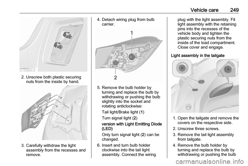
2. Unscrew both plastic securingnuts from the inside by hand.
3. Carefully withdraw the lightassembly from the recesses and
remove.
4. Detach wiring plug from bulb carrier.
5. Remove the bulb holder by turning and replace the bulb by
withdrawing or pushing the bulb
slightly into the socket and rotating anticlockwise:
Tail light/Brake light ( 1)
Turn signal light ( 2)
version with Light Emitting Diode
(LED)
Only turn signal light ( 2) can be
changed.
6. Insert and turn bulb holder clockwise into the tail light
assembly. Connect the wiring
plug with the light assembly. Fit
light assembly with the retaining
pins into the recesses of the
vehicle body and tighten the
plastic securing nuts from the
inside of the load compartment.
Close cover and engage.
Light assembly in the tailgate
1. Open the tailgate and remove the
covers on the respective side.
2. Unscrew three screws.
3. Remove the tail light assembly from tailgate.
4. Remove the bulb holder by turning and replace the bulb by
withdrawing or pushing the bulb
Page 252 of 341

250Vehicle careslightly into the socket androtating anticlockwise:
Tail light ( 1)
Rear fog light/Reverse light ( 2),
depending on the side.
( 2 ) (only one side)
version with Light Emitting Diode
(LED)
Only rear fog light respectively
reverse light ( 2), depending on the
side, can be changed.
5. Insert and turn bulb holder clockwise into the tail light
assembly. Fit the tail light
assembly in the tailgate and
tighten the screws. Attach all
covers.
Side turn signal lights 3-door hatchback
To replace bulb, remove lamp
housing:
1. Slide lamp to its left side and remove with its right end.
2. Turn bulb holder anticlockwiseand remove from housing.
3. Pull bulb from bulb holder and replace it.
Page 253 of 341

Vehicle care2514. Insert bulb holder and turnclockwise.
5. Insert left end of the lamp, slide to
the left and insert right end.
5-door hatchback, 4-door saloon,
Sports tourer
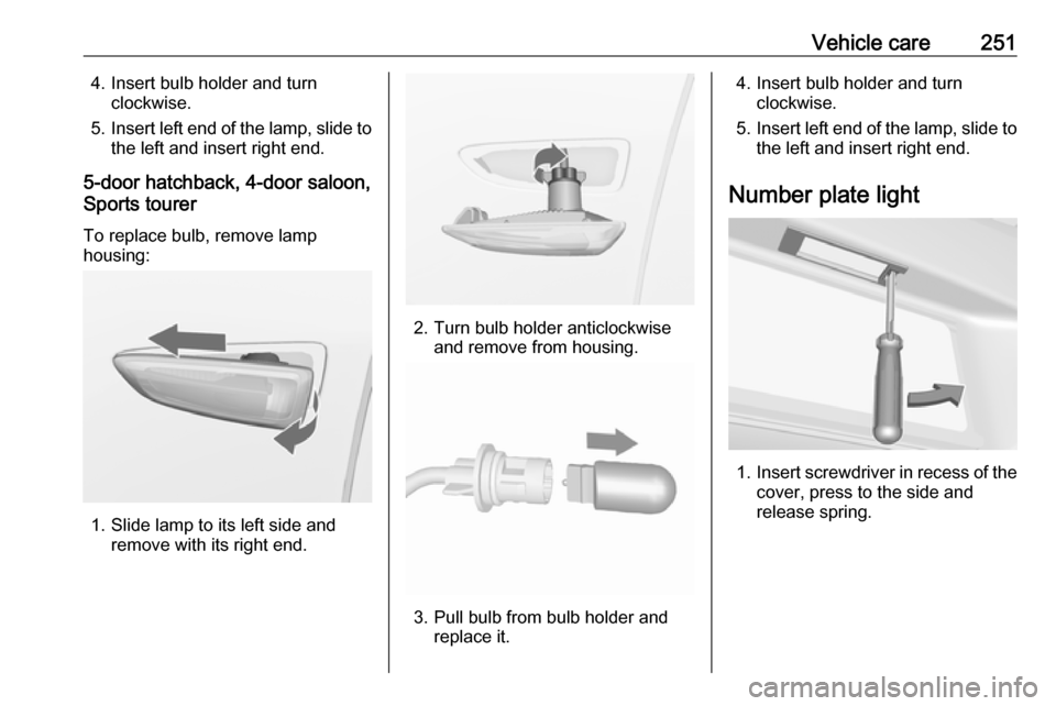
To replace bulb, remove lamp
housing:
1. Slide lamp to its left side and remove with its right end.
2. Turn bulb holder anticlockwiseand remove from housing.
3. Pull bulb from bulb holder and replace it.
4. Insert bulb holder and turnclockwise.
5. Insert left end of the lamp, slide to
the left and insert right end.
Number plate light
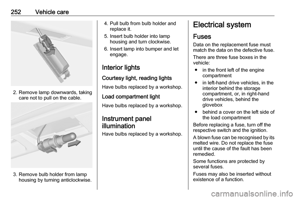
1. Insert screwdriver in recess of the
cover, press to the side and
release spring.
Page 254 of 341

252Vehicle care
2. Remove lamp downwards, takingcare not to pull on the cable.
3. Remove bulb holder from lamphousing by turning anticlockwise.
4. Pull bulb from bulb holder andreplace it.
5. Insert bulb holder into lamp housing and turn clockwise.
6. Insert lamp into bumper and let engage.
Interior lights
Courtesy light, reading lights Have bulbs replaced by a workshop.
Load compartment light
Have bulbs replaced by a workshop.
Instrument panel illumination
Have bulbs replaced by a workshop.Electrical system
Fuses Data on the replacement fuse must
match the data on the defective fuse.
There are three fuse boxes in the
vehicle:
● in the front left of the engine compartment
● in left-hand drive vehicles, in the interior behind the storage
compartment, or, in right-hand
drive vehicles, behind the
glovebox
● behind a cover on the left side of the load compartment
Before replacing a fuse, turn off the
respective switch and the ignition.
A blown fuse can be recognised by its melted wire. Do not replace the fuse
until the cause of the fault has been
remedied.
Some functions are protected by
several fuses.
Fuses may also be inserted without existence of a function.
Page 278 of 341

276Vehicle careStowing a damaged full size
wheel in the spare wheel well,
Sports Tourer and 4-door saloonVehicles equipped with a full size spare wheel:
A damaged full size wheel must be
stowed outside up in the spare wheel
well secured with the wing nut.
The floor cover can be placed on the
projecting wheel.
Vehicles equipped with a temporary
spare wheel:
Secure a damaged full size wheel
outside up with the wing nut in the
spare wheel well after exchanging thethread bolt by an extension bolt,
placed in the tool bag 3 259. To
replace the bolt:
1. Install the hexagon key of the wheel wrench ensuring that it
locates securely on the bolt.
2. Turn the wheel wrench anticlockwise to loosen the bolt.
Remove the bolt.
3. Take the extension bolt from the tool bag 3 259 and screw it in
hand-tight using the hexagon key
of the wheel wrench.
4. Store the tool box and the damaged wheel outside up in the
spare wheel well and secure it by
turning the wing nut clockwise on
the bolt.
The floor cover can be placed on the
projecting wheel.
Replace the extension bolt with the
short bolt before placing the
temporary spare wheel in the well after renewing or repairing the
defective wheel.
Stowing the spare wheel back in
the well after replacing the
damaged wheel
1. Open the floor cover, untwist and remove wing nut.
Only 3-door hatchback: open floor
cover, remove rear storage,
untwist and remove wing nut and
conus.
Page 337 of 341

335Climate control ............................. 15
Climate control systems .............153
Clock........................................... 103
Code ........................................... 124
Control indicators........................ 109
Control of the vehicle .................164
Controls ........................................ 99
Convex shape .............................. 30
Coolant and antifreeze ...............286
Cruise control ....................117, 183
Cupholders .................................. 59
Curtain airbag system .................. 51
Curve lighting.............................. 144
D
Danger, Warnings and Cautions ...4
Daytime running lights ...............144
Declaration of conformity ............328
Diesel fuel system bleeding .......233
Diesel particle filter .............115, 169
Door open .................................. 118
Doors ............................................ 25
Driver assistance systems ..........183
Driver Information Centre ...........118
Driving characteristics and towing tips .............................. 220
Driving hints ................................ 164
E Electric adjustment ......................30
Electrical system......................... 252Electric parking brake .........113, 176
Electric parking brake fault .........114
Electronic climate control system 156
Electronic driving programmes ..173
Electronic Stability Control.......... 179
Electronic Stability Control and Traction Control system ..........115
Electronic Stability Control off .... 115
End-of-life vehicle recovery .......226
Engine compartment fuse box ...253
Engine coolant ........................... 229
Engine coolant temperature gauge ..................................... 107
Engine data ............................... 293
Engine exhaust .......................... 169
Engine identification ...................289
Engine oil ................... 228, 286, 290
Engine oil pressure ....................116
Entry lighting .............................. 151
Event data recorders ..................332
Exit lighting ................................ 151
Exterior care .............................. 282
Exterior light ............................... 117
Exterior lighting ....................13, 140
Exterior mirrors ............................. 30
F
Fault ........................................... 173
First aid ......................................... 93
First aid kit ................................... 93Fixed air vents ........................... 161
Flex-Fix system ............................ 63
Fog light ..................................... 117
Fog lights ................................... 238
Folding mirrors ............................. 30
Following distance indication ......196
Forward collision alert................. 193
Front airbag system .....................49
Front fog lights ........................... 148
Front seats.................................... 39
Front storage ................................ 60
Front turn signal lights ...............240
Fuel............................................. 213
Fuel consumption - CO 2-
Emissions ............................... 219
Fuel for diesel engines ..............213
Fuel for liquid gas operation .......214
Fuel for petrol engines ...............213
Fuel gauge ................................. 107 Fuel selector .............................. 107
Fuses ......................................... 252
G
Gauges ....................................... 106
General information ...................219
Glass panel .................................. 36
Glovebox ..................................... 59
Graphic-Info-Display, Colour- Info-Display ............................ 122