key VAUXHALL ASTRA J 2018 Workshop Manual
[x] Cancel search | Manufacturer: VAUXHALL, Model Year: 2018, Model line: ASTRA J, Model: VAUXHALL ASTRA J 2018Pages: 311, PDF Size: 9.37 MB
Page 168 of 311

166Driving and operatingapprox. 30 seconds before
switching off, in order to protect
the turbocharger.
Notice
In the event of an accident with airbag deployment, the engine is
switched off automatically if the
vehicle comes to a standstill within a certain time.
Emergency operation under
extreme cold temperatures
9 Warning
This emergency operation may
only be carried out in case of
extremely cold temperatures and if the vehicle is parked on a levelsurface.
In countries with extreme cold
temperatures it may be necessary to
park the vehicle without applied
parking brake.
This is an emergency operation to
avoid freezing of the parking brake.
Vehicles equipped with manual
transmission automated, electric
parking brake and power button
On vehicles with manual transmission
automated the ignition can only be
switched off if the parking brake is
applied. Therefore the following items must be carried out to release the
electric parking brake:
1. Apply electric parking brake and switch off ignition.
2. Switch on ignition by pressing and
holding Engine Start/Stop for six
seconds without operating brake
pedal.
3. Press brake pedal and release electric parking brake.
4. Switch off ignition.
Vehicles equipped with manual
transmission automated, electric
parking brake and ignition switch
On vehicles with manual transmission
automated the ignition can only be
switched off if the parking brake is
applied. Therefore the following items
must be carried out to release the
electric parking brake:1. Apply electric parking brake and switch off ignition.
2. Press brake pedal and release electric parking brake.
3. Remove key from ignition switch.
Page 172 of 311
170Driving and operatingParking
Apply the parking brake and engage
P .
The ignition key can only be removed
when the selector lever is in position
P .
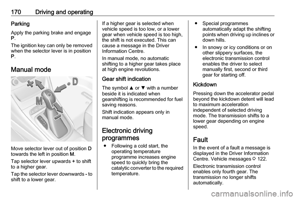
Manual mode
Move selector lever out of position D
towards the left in position M.
Tap selector lever upwards + to shift
to a higher gear.
Tap the selector lever downwards - to
shift to a lower gear.
If a higher gear is selected when
vehicle speed is too low, or a lower
gear when vehicle speed is too high,
the shift is not executed. This can
cause a message in the Driver
Information Centre.
In manual mode, no automatic
shifting to a higher gear takes place
at high engine revolutions.
Gear shift indication
The symbol R or S with a number
beside it is indicated when
gearshifting is recommended for fuel
saving reasons.
Shift indication appears only in
manual mode.
Electronic driving programmes
● Following a cold start, the operating temperature
programme increases engine
speed to quickly bring the
catalytic converter to the required
temperature.● Special programmes automatically adapt the shifting
points when driving up inclines or
down hills.
● In snowy or icy conditions or on other slippery surfaces, the
electronic transmission control
enables the driver to select
manually first, second or third
gear for starting off.
Kickdown Pressing down the accelerator pedal
beyond the kickdown detent will lead
to maximum acceleration
independent of selected driving
mode. The transmission shifts to a
lower gear depending on engine
speed.
Fault
In the event of a fault a message is
displayed in the Driver Information
Centre. Vehicle messages 3 122.
Electronic transmission control
enables only fourth gear. The
transmission no longer shifts
automatically.
Page 173 of 311
Driving and operating171Have the cause of the fault remedied
by a workshop.
Interruption of power supply In the event of an interruption of
power supply, the selector lever
cannot be moved out of the P
position. The ignition key cannot be
removed from the ignition switch.
If the vehicle battery is discharged,
start the vehicle using jump leads
3 268.
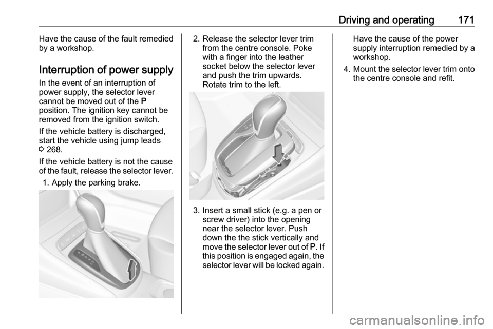
If the vehicle battery is not the cause
of the fault, release the selector lever.
1. Apply the parking brake.2. Release the selector lever trim from the centre console. Poke
with a finger into the leather
socket below the selector lever
and push the trim upwards.
Rotate trim to the left.
3. Insert a small stick (e.g. a pen or screw driver) into the opening
near the selector lever. Push
down the the stick vertically and
move the selector lever out of P. If
this position is engaged again, the
selector lever will be locked again.
Have the cause of the power
supply interruption remedied by a
workshop.
4. Mount the selector lever trim onto
the centre console and refit.
Page 176 of 311

174Driving and operatingThe vehicle starts to move when the
brake pedal is released.
To start-off without depressing the
brake pedal, accelerate immediately
after engaging a gear as long as D or
R flashes.
If neither the accelerator nor the
brake pedal are depressed, no gear
is engaged and D or R flashes for a
brief time in the display.
Stopping the vehicle
In D, first gear is engaged and the
clutch is released when the vehicle is stopped. In R, reverse gear remains
engaged.
Engine braking
Automatic mode
When driving downhill, the manual
transmission automated does not
shift into higher gears until a fairly
high engine speed has been reached.
It shifts down in good time when
braking.Manual mode
To utilise the engine braking effect, select a lower gear in good time when driving downhill. Changing into
manual mode is only possible while
the engine is running or during an
Autostop.
Rocking the vehicle Rocking the vehicle is only
permissible if the vehicle is stuck in
sand, mud or snow. Move the selector
lever between R and D in a repeat
pattern. Do not race the engine and
avoid sudden acceleration.
Parking The most recently engaged gear (seetransmission display) remains
engaged when switching off ignition.
With N, no gear is engaged.
Therefore always apply the parking
brake when switching off ignition. If
parking brake is not applied, P flashes
in the transmission display and the
key cannot be removed from the
ignition switch. P stops flashing in the
transmission display as soon as the
parking brake is slightly applied.When the ignition is switched off, the
transmission no longer responds to
movement of the selector lever.
Emergency operation to avoid
freezing of the parking brake 3 165.
Manual mode
If a higher gear is selected when the engine speed is too low, or a lower
gear when the speed is too high, the
shift is not executed. This prevents
the engine from running at too low or
too high an engine speed. A warning
message is displayed in the Driver
Information Centre. Vehicle
messages 3 122.
If engine speed is too low, the
transmission automatically shifts to a
lower gear.
When + or - is selected in automatic
mode, the transmission switches to
manual mode and shifts accordingly.
Gear shift indication
The symbol R or S with a number
beside is indicated when gearshifting
is recommended for fuel saving
reasons.
Page 225 of 311
Driving and operating223
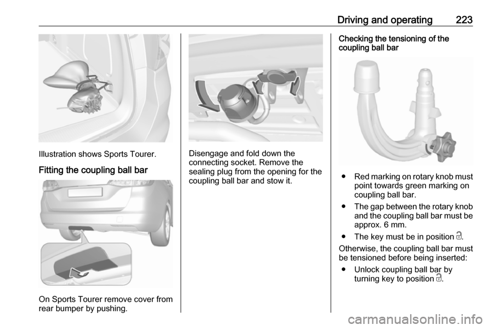
Illustration shows Sports Tourer.Fitting the coupling ball bar
On Sports Tourer remove cover from
rear bumper by pushing.
Disengage and fold down the
connecting socket. Remove the
sealing plug from the opening for the
coupling ball bar and stow it.
Checking the tensioning of the
coupling ball bar
● Red marking on rotary knob must
point towards green marking on
coupling ball bar.
● The gap between the rotary knob
and the coupling ball bar must be approx. 6 mm.
● The key must be in position c.
Otherwise, the coupling ball bar must be tensioned before being inserted:
● Unlock coupling ball bar by turning key to position c.
Page 226 of 311
224Driving and operating
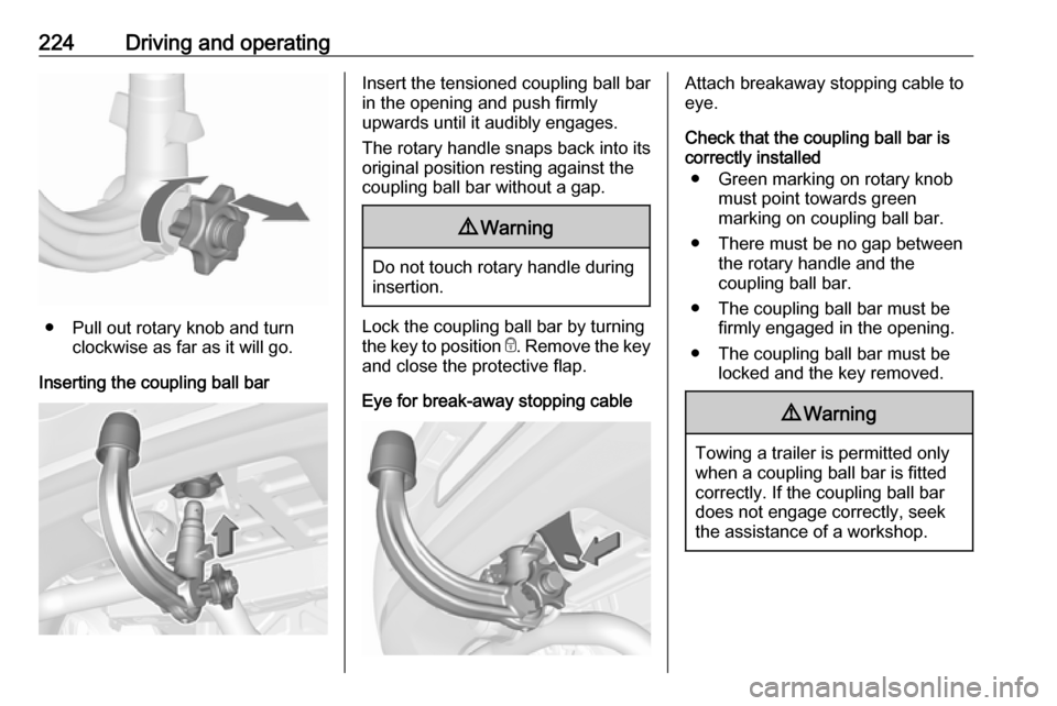
● Pull out rotary knob and turnclockwise as far as it will go.
Inserting the coupling ball bar
Insert the tensioned coupling ball bar
in the opening and push firmly
upwards until it audibly engages.
The rotary handle snaps back into its
original position resting against the
coupling ball bar without a gap.9 Warning
Do not touch rotary handle during
insertion.
Lock the coupling ball bar by turning
the key to position e. Remove the key
and close the protective flap.
Eye for break-away stopping cable
Attach breakaway stopping cable to
eye.
Check that the coupling ball bar is correctly installed
● Green marking on rotary knob must point towards green
marking on coupling ball bar.
● There must be no gap between the rotary handle and the
coupling ball bar.
● The coupling ball bar must be firmly engaged in the opening.
● The coupling ball bar must be locked and the key removed.9Warning
Towing a trailer is permitted only
when a coupling ball bar is fitted correctly. If the coupling ball bardoes not engage correctly, seekthe assistance of a workshop.
Page 227 of 311
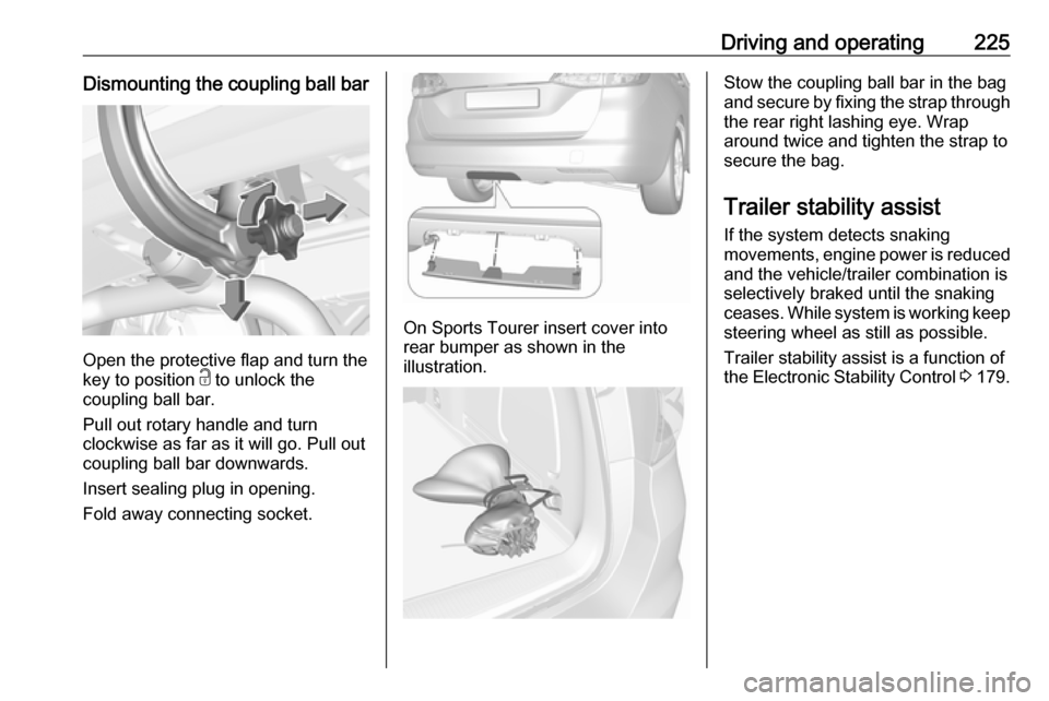
Driving and operating225Dismounting the coupling ball bar
Open the protective flap and turn the
key to position c to unlock the
coupling ball bar.
Pull out rotary handle and turn
clockwise as far as it will go. Pull out coupling ball bar downwards.
Insert sealing plug in opening.
Fold away connecting socket.
On Sports Tourer insert cover into
rear bumper as shown in the
illustration.
Stow the coupling ball bar in the bag
and secure by fixing the strap through the rear right lashing eye. Wrap
around twice and tighten the strap to
secure the bag.
Trailer stability assist
If the system detects snaking
movements, engine power is reduced
and the vehicle/trailer combination is selectively braked until the snaking
ceases. While system is working keep
steering wheel as still as possible.
Trailer stability assist is a function of
the Electronic Stability Control 3 179.
Page 251 of 311
Vehicle care249No.Circuit17Body control module18Body control module19Data link connector20Airbag system21Climate control system22Central locking system, tailgate23Electronic key system24Power seat memory function25Airbag system steering wheel26Ignition switch/Steering column
lock27Body control module28USB socket29–30Selector lever31Rear window wiper32Transmission control moduleNo.Circuit33Anti-theft alarm system/Power
sounder34Parking assist/Side blind spot
alert/Infotainment system/USB
socket35OnStar36Info display/Instrument cluster/ CD player37Infotainment system, radio
After having changed defective fuses,
close the fuse box cover and press
until it engages.
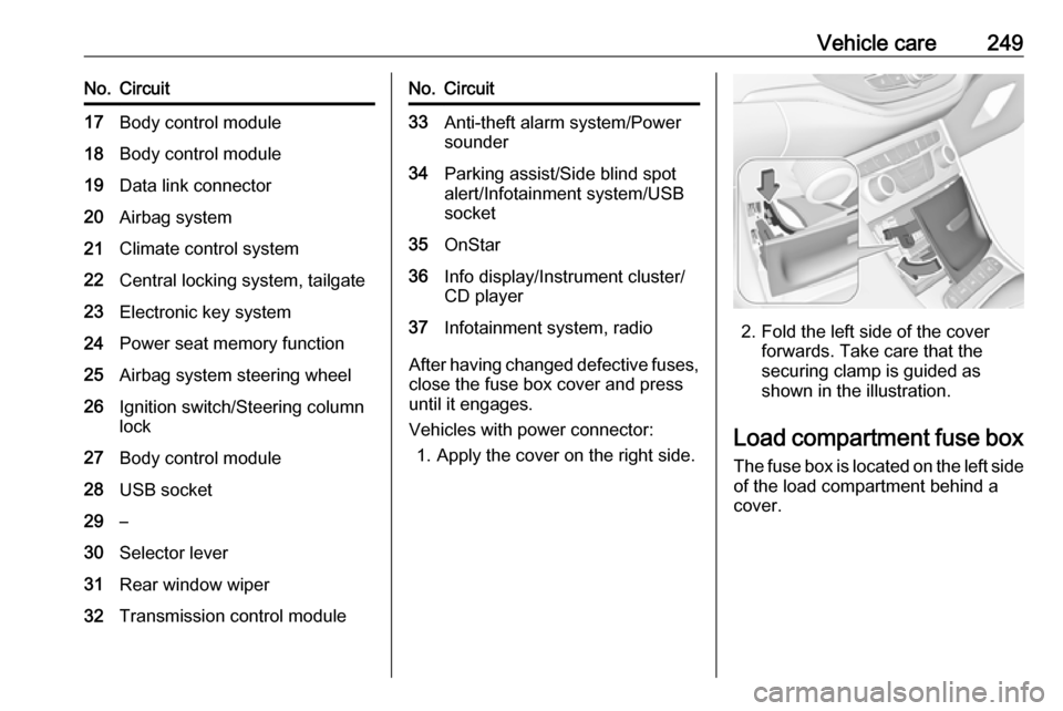
Vehicles with power connector: 1. Apply the cover on the right side.
2. Fold the left side of the cover forwards. Take care that the
securing clamp is guided as
shown in the illustration.
Load compartment fuse box
The fuse box is located on the left side
of the load compartment behind a
cover.
Page 298 of 311

296Customer informationCustomer
informationCustomer information ................296
Declaration of conformity .........296
REACH .................................... 298
Collision damage repair ...........298
Software acknowledgement ....298
Software update ......................300
Registered trademarks ............300
Vehicle data recording and pri‐
vacy ........................................... 301
Event data recorders ...............301
Radio Frequency Identification (RFID) ..................................... 302Customer information
Declaration of conformity
Radio transmission systems
This vehicle has systems that
transmit and/or receive radio waves subject to Directive 1999/5/EC or
2014/53/EU. These systems are in compliance with the essential
requirements and other relevant
provisions of Directive 1999/5/EC or 2014/53/EU. Copies of the original
Declarations of Conformity can be
obtained on our website.
Antenna
Laird
8100 Industrial Park Drive, Grand
Blanc, MI, 48439, USA
Operation frequency: N/A
Maximum output: N/A
Kathrein Automotive North America,
Inc.
3967 W. Hamlin Rd., Rochester Hills, MI 48309, USA
Operation frequency: N/AMaximum output: N/A
Electronic key
Denso Coperation
Waldeckerstraße 11, 64546
Mörfelden-Walldorf, Germany
Operation frequency: 433,92 MHz
Maximum output: -5,88 dBm
Electronic key module
Denso Coperation
Waldeckerstraße 11, 64546
Mörfelden-Walldorf, Germany
Operation frequency: 125 kHz
Maximum output: -0,14 dBm
Front radar unit
Continental Automotive GmbH
ADC Automotive Distance Control
Systems GmbH, Peter-Dornier-
Straße 10, 88131 Lindau, Germany
Operation frequency: 76-77 GHz
Maximum output: 30 EIRP dBm
Immobiliser
Bosch
Robert Bosch GmbH, Robert Bosch
Platz 1, 70839 Gerlingen, Germany
Page 307 of 311

305Collision damage repair..............298
Control indicators........................ 108
Control of the vehicle .................157
Controls ........................................ 90
Convex shape .............................. 38
Coolant and antifreeze ...............276
Cruise control ....................113, 181
Cupholders .................................. 70
Curtain airbag system .................. 62
Curve lighting.............................. 137
D Danger, Warnings and Cautions ...4
Daytime running lights ...............137
Declaration of conformity ............296
Diesel fuel system bleeding .......233
Diesel particle filter ....................167
Door open .................................. 114
Doors ............................................ 29
Driver assistance systems ..........181
Driver Information Centre ...........114
Driving characteristics and towing tips .............................. 221
Driving hints ................................ 157
E Electric adjustment ......................38
Electrical system......................... 244
Electric parking brake .........110, 176
Electric parking brake fault .........110
Electronic climate control system 149Electronic driving programmes .
........................................ 170, 175
Electronic key system ...................21
Electronic Stability Control.......... 179
Electronic Stability Control and Traction Control system ..........111
Electronic Stability Control off..... 111
End-of-life vehicle recovery .......227
Engine compartment fuse box ...245
Engine coolant ........................... 230
Engine coolant temperature gauge ..................................... 106
Engine data ............................... 284
Engine exhaust .......................... 167
Engine identification ...................280
Engine oil ................... 229, 276, 281
Engine oil pressure ....................112
Entry lighting .............................. 144
Event data recorders ..................301
Exit lighting ................................ 144
Exterior care .............................. 272
Exterior light ............................... 113
Exterior lighting ....................12, 135
Exterior mirrors ............................. 38
F Fault ................................... 170, 175
First aid kit ................................... 86
Fixed air vents ........................... 154
Fog light ..................................... 113Fog lights ................................... 236
Folding mirrors ............................. 38
Following distance ......................111
Following distance indication ......195
Forward collision alert................. 192
Fragrance diffuser ........................97
Front airbag system .....................61
Front fog lights ........................... 141
Front seats.................................... 46
Front storage ................................ 71
Fuel............................................. 216
Fuel consumption - CO 2-
Emissions ............................... 220
Fuel for diesel engines ..............217
Fuel for natural gas operation ...218
Fuel for petrol engines ...............216
Fuel gauge ................................. 105
Fuel selector .............................. 105
Fuses ......................................... 244
G
Gauges ....................................... 103
Gear shifting ............................... 111
General information ...................221
Glovebox ..................................... 70
H Halogen headlights ....................234
Hand brake ......................... 175, 176
Hazard warning flashers ............140
Headlight flash ........................... 136