stop start VAUXHALL ASTRA J GTC 2018.5 Owner's Guide
[x] Cancel search | Manufacturer: VAUXHALL, Model Year: 2018.5, Model line: ASTRA J GTC, Model: VAUXHALL ASTRA J GTC 2018.5Pages: 293, PDF Size: 8.28 MB
Page 147 of 293

Driving and operating145Automatic cleaning processThe exhaust filter system filters
harmful soot particles out of the
exhaust gases. The system includes
a self-cleaning function that runs
automatically during driving without
any notification. The filter is cleaned
by periodically burning off the soot
particles at high temperature. This
process takes place automatically
under set driving conditions and may
take up to 25 minutes. Typically it
needs between seven and twelve
minutes. Autostop is not available
and fuel consumption may be higher
during this period. The emission of
smells and smoke during this process is normal.System requires cleaning
Under certain conditions, e.g. driving
short distances, the system cannot
clean itself automatically.
If cleaning of the filter is required and if previous driving conditions did not
enable automatic cleaning, it will be
indicated by illumination of % and a
warning message in the Driver
Information Centre.
% illuminates along with a warning
message when exhaust filter is full.
Start cleaning process as soon as
possible.
% flashes along with a warning
message when exhaust filter has
reached the maximum filling level.
Start cleaning process immediately to
avoid damage to the engine.
Activate self-cleaning process
To activate cleaning process,
continue driving, keep engine speed
above 2000 rpm. Shift down if
necessary. Exhaust filter cleaning is
then started.
Cleaning process is completed more quickly at high engine speeds and
loads.
Control indicator % extinguishes as
soon as the self-cleaning operation is complete. Keep on driving until self-
cleaning operation is complete.Caution
If possible, do not interrupt
cleaning process. Drive until
cleaning is completed to avoid the
need for service or repair by a
workshop.
Page 150 of 293

148Driving and operatingThe engine can only be started with
the lever in position P or N. When
position N is selected, press the brake
pedal or apply the parking brake
before starting.
Do not accelerate while engaging a
gear. Never depress the accelerator
pedal and brake pedal at the same
time.
When a gear is engaged, the vehicle
slowly begins to creep when the
brake is released.
Engine braking To utilise the engine braking effect,select a lower gear in good time when
driving downhill, see manual mode.
Rocking the vehicle
Rocking the vehicle is only
permissible if the vehicle is stuck in
sand, mud or snow. Move the selector
lever between D and R in a repeat
pattern. Do not race the engine and
avoid sudden acceleration.Parking
Apply the parking brake and engage
P .
The ignition key can only be removed
when the selector lever is in position
P .
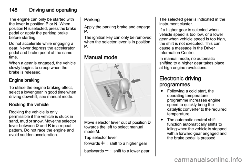
Manual mode
Move selector lever out of position D
towards the left to select manual
mode M.
Tap selector lever
forwards <:shift to a higher gearbackwards ]:shift to a lower gearThe selected gear is indicated in the
instrument cluster.
If a higher gear is selected when
vehicle speed is too low, or a lower
gear when vehicle speed is too high,
the shift is not executed. This can
cause a message in the Driver
Information Centre.
In manual mode, no automatic
shifting to a higher gear takes place
at high engine revolutions.
Electronic driving programmes
● Following a cold start, the operating temperature
programme increases engine
speed to quickly bring the
catalytic converter to the required
temperature.
● The automatic neutral shift function automatically shifts to
idling when the vehicle is stopped with a forward gear engaged andthe brake pedal is pressed.
Page 155 of 293

Driving and operating153brake automatically. This is not
possible when the switch m is pulled
at the same time.
Vehicles with automatic transmission:
Engaging D and then depressing the
accelerator pedal releases the
electric parking brake automatically.
This is not possible when the switch
m is pulled at the same time.
Dynamic braking when vehicle is
moving
When the vehicle is moving and the
switch m is kept pulled, the electric
parking brake system will decelerate the vehicle, but will not apply
statically.
As soon as the switch m is released,
dynamic braking will be stopped.
Fault
Failure mode of electric parking brake
is indicated by control indicator j and
by a code number or a vehicle
message which is displayed in the
Driver Information Centre. Vehicle
messages 3 98.Apply electric parking brake: pull and
hold the switch m for more than five
seconds . If control indicator m
illuminates, electric parking brake is
applied.
Release electric parking brake: push
and hold the switch m for more than
two seconds. If control indicator m
extinguishes, electric parking brake is
released.
Control indicator m flashes: electric
parking brake is not fully applied or released. When continuously
flashing, release electric parking
brake and retry applying.
Brake assist
If the brake pedal is depressed
quickly and forcefully, maximum
brake force is automatically applied
(full braking).
Maintain steady pressure on the
brake pedal for as long as full braking
is required. Maximum brake force is
automatically reduced when the
brake pedal is released.Hill start assist
The system helps prevent unintendedmovement when driving away on
inclines.
When releasing the brake pedal after
stopping on an incline, the brakes
remain on for a further two seconds.
The brakes release automatically as
soon as the vehicle begins to
accelerate.
The hill start assist is not active during
an Autostop.
Page 180 of 293

178Driving and operating● Advanced parking assist isactive: short press activates
front-rear parking assist.
● Advanced parking assist is active: long press deactivatesadvanced parking assist.
● Advanced parking assist and front-rear parking assist are
active: short press deactivates
both systems.
Activation
When searching for a parking slot, the
system must be activated by pressing D for approx. one second.
The system can only be activated and
can only search for a parking slot at a speed up to 18 mph.
The maximum allowed parallel
distance between the vehicle and a
row of parked cars is 1.8 metres.
Functionality
When the vehicle passes a row of
cars and the system is activated, the
advanced parking assist system
begins searching for a suitable
parking slot. When a suitable slot is
detected, visual feedback in the
Driver Information Centre and an
acoustic signal are given.
If the driver does not stop the vehicle
within ten metres after a parking slot
is proposed, the system starts to
search for another suitable parking
slot.
The parking slot suggestion of the
system is accepted when the vehicle is stopped by the driver within ten
metres after the "Stop" message is
given. The system calculates the
optimal route into the parking slot.
Then it manoeuvres the driver into the
slot by giving detailed instructions.
Page 203 of 293

Vehicle care201
Move the safety catch sideways to theleft vehicle side and open the bonnet.
Secure the bonnet support.
If the bonnet is opened during an
Autostop, the engine will be restarted automatically for safety reasons.
Closing
Before closing the bonnet, press the
support into the holder.
Lower the bonnet and allow it to fall
into the latch from a low height
(20-25 cm). Check that the bonnet is engaged.Caution
Do not press the bonnet into the
latch, to avoid dents.
Engine oil
Check the engine oil level manually
on a regular basis to prevent damage
to the engine. Ensure that the correct specification of oil is used.
Recommended fluids and lubricants
3 253.
The maximum engine oil
consumption is 0.6 l per 1000 km.
Check with the vehicle on a level
surface. The engine must be at
operating temperature and switched
off for at least five minutes.Caution
It is the owner's responsibility to
maintain the proper level of an
appropriate quality oil in the
engine.
Pull out the dipstick, wipe it clean,
reinsert it fully, pull out and read the
engine oil level.
Different dipsticks are used
depending on engine variant.
Page 207 of 293

Vehicle care205Vehicle battery discharge protection
3 127.
Disconnecting the battery
If the vehicle's battery is to be
disconnected (e.g. for maintenance
work), the alarm siren must be
deactivated as follows: Switch the
ignition on then off, then disconnect
the vehicle's battery within
15 seconds.
Replacing the vehicle battery Notice
Any deviation from the instructions
given in this section may lead to
temporary deactivation or
disturbance of the stop-start system.
When the vehicle battery is being replaced, please ensure that there
are no open ventilation holes in the
vicinity of the positive terminal. If a
ventilation hole is open in this area, it
must be closed off with a dummy cap,
and the ventilation in the vicinity of the
negative terminal must be opened.
Only use vehicle batteries that allow
the fuse box to be mounted above the
vehicle battery.Ensure that the battery is always replaced by the same type of battery.
We recommend that you have the
vehicle battery replaced by a
workshop.
Stop-start system 3 141.
Charging the vehicle battery9 Warning
On vehicles with stop-start
system, ensure that the charging potential does not exceed
14.6 volts when using a battery
charger. Otherwise the vehicle
battery might be damaged.
Jump starting 3 245.
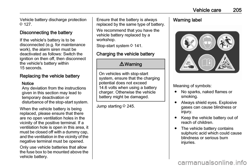
Warning label
Meaning of symbols:
● No sparks, naked flames or smoking.
● Always shield eyes. Explosive gases can cause blindness or
injury.
● Keep the vehicle battery out of reach of children.
● The vehicle battery contains sulphuric acid which could cause
blindness or serious burn
injuries.
Page 225 of 293

Vehicle care223No.Circuit16Starter17Transmission control module18Heated rear window19Front power windows20Rear power windows21Rear electrical centre22Left high beam (Halogen)23Headlamp washer system24Right low beam (Xenon)25Left low beam (Xenon)26Front fog lights27Diesel fuel heating28Start stop system29Electric parking brake30ABS31Adaptive cruise control32AirbagNo.Circuit33Adaptive forward lighting/Auto‐
matic light control34Exhaust gas recirculation35Exterior mirror/Rain sensor36Climate control37Canister vent solenoid38Vacuum pump39Central control module40Windscreen washer/Rear
window washer system41Right high beam (Halogen)42Radiator fan43Windscreen wiper44Windscreen wiper45Radiator fan46–47Horn48Radiator fanNo.Circuit49Fuel pump50Headlamp levelling/Adaptive
forward lighting51Air shutter52Auxiliary heater/Diesel engine53Transmission control module/
Engine control module54Vacuum pump/Instrument
panel cluster/Heating ventila‐
tion/Air conditioning system
After having changed defective fuses,
close the fuse box cover and press
until it engages.
If the fuse box cover is not closed
correctly, malfunction may occur.
Page 234 of 293

232Vehicle care
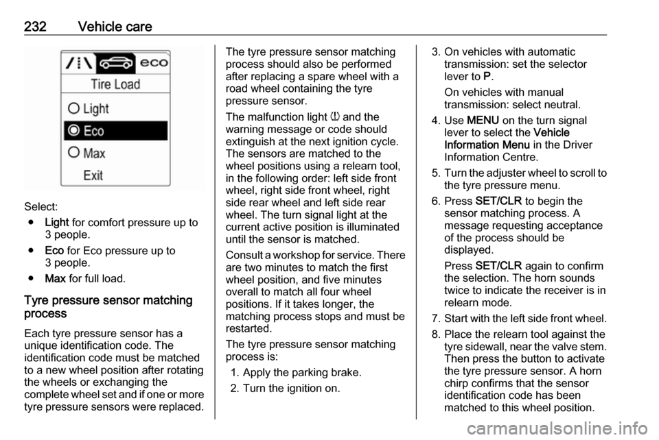
Select:● Light for comfort pressure up to
3 people.
● Eco for Eco pressure up to
3 people.
● Max for full load.
Tyre pressure sensor matching
process
Each tyre pressure sensor has a
unique identification code. The
identification code must be matched
to a new wheel position after rotating the wheels or exchanging the
complete wheel set and if one or more
tyre pressure sensors were replaced.
The tyre pressure sensor matching
process should also be performed
after replacing a spare wheel with a
road wheel containing the tyre
pressure sensor.
The malfunction light w and the
warning message or code should
extinguish at the next ignition cycle.
The sensors are matched to the
wheel positions using a relearn tool,
in the following order: left side front
wheel, right side front wheel, right
side rear wheel and left side rear
wheel. The turn signal light at the
current active position is illuminated
until the sensor is matched.
Consult a workshop for service. There
are two minutes to match the first
wheel position, and five minutes
overall to match all four wheel
positions. If it takes longer, the
matching process stops and must be
restarted.
The tyre pressure sensor matching
process is:
1. Apply the parking brake.
2. Turn the ignition on.3. On vehicles with automatic transmission: set the selector
lever to P.
On vehicles with manual
transmission: select neutral.
4. Use MENU on the turn signal
lever to select the Vehicle
Information Menu in the Driver
Information Centre.
5. Turn the adjuster wheel to scroll to
the tyre pressure menu.
6. Press SET/CLR to begin the
sensor matching process. A
message requesting acceptance
of the process should be
displayed.
Press SET/CLR again to confirm
the selection. The horn sounds
twice to indicate the receiver is in
relearn mode.
7. Start with the left side front wheel.
8. Place the relearn tool against the tyre sidewall, near the valve stem.Then press the button to activate
the tyre pressure sensor. A horn
chirp confirms that the sensor
identification code has been
matched to this wheel position.
Page 254 of 293

252Service and maintenanceService and
maintenanceGeneral information ...................252
Service information ..................252
Recommended fluids, lubricants
and parts .................................... 253
Recommended fluids and lubricants ................................ 253General information
Service information In order to ensure economical and
safe vehicle operation and to
maintain the value of your vehicle, it
is of vital importance that all
maintenance work is carried out at the proper intervals as specified.
The detailed, up-to-date service
schedule for your vehicle is available
at the workshop.
Service display 3 82.
European service intervals
Maintenance of your vehicle is
required every 20,000 miles or after
1 year , whichever occurs first, unless
otherwise indicated in the service
display.
A shorter service interval can be valid
for severe driving behaviour, e.g. for
taxis and police vehicles.
The European service intervals are
valid for the following countries:Andorra, Austria, Belgium, Bosnia-
Herzegovina, Bulgaria, Croatia,
Cyprus, Czech Republic, Denmark,
Estonia, Finland, France, Germany,
Greece, Greenland, Hungary,
Iceland, Ireland, Italy, Latvia,
Liechtenstein, Lithuania,
Luxembourg, Macedonia, Malta,
Monaco, Montenegro, Netherlands,
Norway, Poland, Portugal, Romania, San Marino, Serbia, Slovakia,
Slovenia, Spain, Sweden,
Switzerland, United Kingdom.
Service display 3 82.
International service intervals Maintenance of your vehicle is
required every 10,000 miles or after
1 year , whichever occurs first, unless
otherwise indicated in the service
display.
A shorter service interval can be valid for severe driving behaviour. Severe
operating conditions exist if one or
more of the following circumstances occur frequently: Cold starting, stop
and go operation, trailer operation,
mountain driving, driving on poor and
sandy road surfaces, increased air
Page 291 of 293

289Power outlets ............................... 77
Power seat adjustment ................43
Power steering.............................. 88
Power steering fluid ....................203
Power windows ............................ 32
Preheating ................................... 89
Puncture ..................................... 237
Q Quickheat ................................... 135
R Radio Frequency Identification (RFID) .................................... 284
Radio remote control ...................21
REACH ....................................... 279
Reading lights ............................ 125
Rear floor storage cover ..............66
Rear fog light ............................... 91
Rear fog lights ........................... 123
Rear seats .................................... 46
Rear storage ................................. 65
Rear window wiper and washer ..75
Recommended fluids and lubricants ........................ 253, 258
Reduced engine power ................91
Refuelling ................................... 189 Registered trademarks ...............281
Retained power off .....................140
Reversing lights .........................124
Ride control systems ..................154Roof.............................................. 34
Roof load ...................................... 69
Roof rack ..................................... 69
S Safety belts ................................... 46
Seat adjustment ............................. 7 Seat belt ........................................ 9
Seat belt reminder .......................86
Seat belts ..................................... 46
Seat folding .................................. 42
Seat heating ................................. 45
Seat position ................................ 39
Selector lever ............................. 147 Service ............................... 137, 252
Service display ............................ 82
Service information ....................252
Service vehicle soon .................... 87
Side airbag system ......................50
Side blind spot alert ....................181
Sidelights .................................... 115
Side turn lights ........................... 218
Smartphone controller ..................98
Software acknowledgement .......279
Spare wheel ............................... 241
Speed limiter............................... 160
Speedometer ............................... 79
Starting and operating ................139
Starting off ................................... 18
Starting the engine ....................140Steering...................................... 139
Steering wheel adjustment ....10, 72
Steering wheel controls ...............72
Stop-start system........................ 141
Storage ......................................... 59
Storage compartments .................59
Sunroof ........................................ 34
Sunvisor lights ........................... 125
Sun visors .................................... 34
Symbols ......................................... 4
T
Tachometer ................................. 79
Tail lights ................................... 215
Three-point seat belt .................... 47
Tools .......................................... 226
Tow bar....................................... 193 Towing ................................ 193, 246
Towing another vehicle .............247
Towing equipment .....................194
Towing the vehicle .....................246
Traction Control system ............. 154
Traction Control system off .......... 89
Traffic sign assistant ...................182
Trailer coupling ........................... 193
Trailer stability assist .................197
Trailer towing ............................. 193
Transmission ............................... 17
Transmission display .................146
Tread depth ............................... 233