key VAUXHALL ASTRA K 2018.75 Workshop Manual
[x] Cancel search | Manufacturer: VAUXHALL, Model Year: 2018.75, Model line: ASTRA K, Model: VAUXHALL ASTRA K 2018.75Pages: 319, PDF Size: 9.71 MB
Page 173 of 319
Driving and operating171The vehicle must be parked on a level
surface.
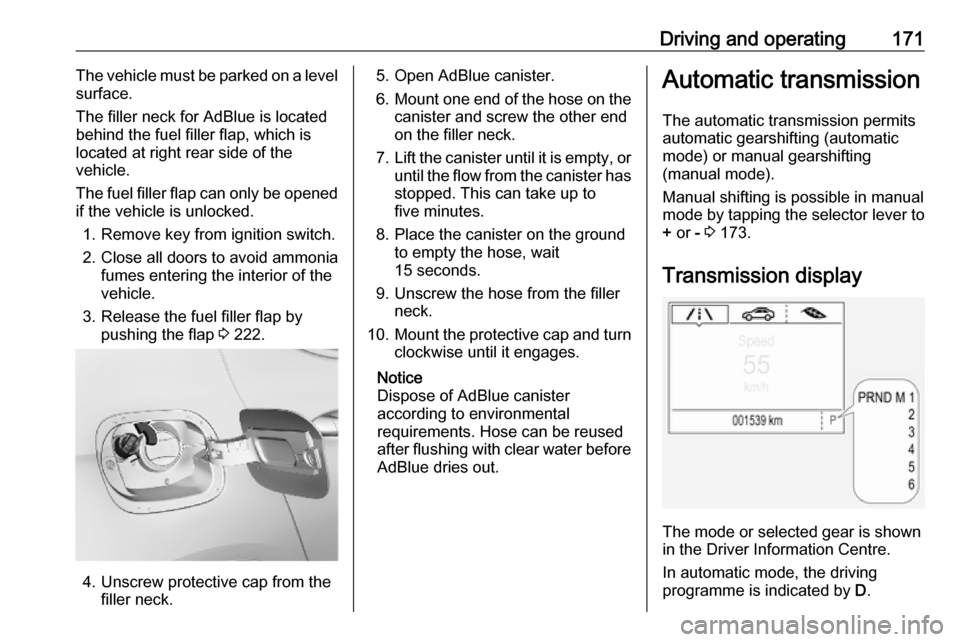
The filler neck for AdBlue is located
behind the fuel filler flap, which is located at right rear side of the
vehicle.
The fuel filler flap can only be opened if the vehicle is unlocked.
1. Remove key from ignition switch.2. Close all doors to avoid ammonia fumes entering the interior of the
vehicle.
3. Release the fuel filler flap by pushing the flap 3 222.
4. Unscrew protective cap from the
filler neck.
5. Open AdBlue canister.
6. Mount one end of the hose on the
canister and screw the other end
on the filler neck.
7. Lift the canister until it is empty, or
until the flow from the canister has stopped. This can take up to
five minutes.
8. Place the canister on the ground to empty the hose, wait
15 seconds.
9. Unscrew the hose from the filler neck.
10. Mount the protective cap and turn
clockwise until it engages.
Notice
Dispose of AdBlue canister
according to environmental
requirements. Hose can be reused
after flushing with clear water before
AdBlue dries out.Automatic transmission
The automatic transmission permits
automatic gearshifting (automatic
mode) or manual gearshifting
(manual mode).
Manual shifting is possible in manual
mode by tapping the selector lever to + or - 3 173.
Transmission display
The mode or selected gear is shown
in the Driver Information Centre.
In automatic mode, the driving
programme is indicated by D.
Page 175 of 319
Driving and operating173ParkingApply the parking brake and engage
P .
The ignition key can only be removed
when the selector lever is in position
P .
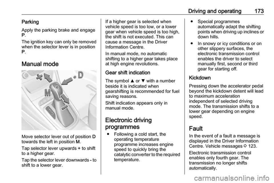
Manual mode
Move selector lever out of position D
towards the left in position M.
Tap selector lever upwards + to shift
to a higher gear.
Tap the selector lever downwards - to
shift to a lower gear.
If a higher gear is selected when
vehicle speed is too low, or a lower
gear when vehicle speed is too high,
the shift is not executed. This can
cause a message in the Driver
Information Centre.
In manual mode, no automatic
shifting to a higher gear takes place
at high engine revolutions.
Gear shift indication
The symbol R or S with a number
beside it is indicated when
gearshifting is recommended for fuel
saving reasons.
Shift indication appears only in
manual mode.
Electronic driving programmes
● Following a cold start, the operating temperature
programme increases engine
speed to quickly bring the
catalytic converter to the required
temperature.● Special programmes automatically adapt the shifting
points when driving up inclines or
down hills.
● In snowy or icy conditions or on other slippery surfaces, the
electronic transmission control
enables the driver to select
manually first, second or third
gear for starting off.
Kickdown Pressing down the accelerator pedal
beyond the kickdown detent will lead
to maximum acceleration
independent of selected driving
mode. The transmission shifts to a
lower gear depending on engine
speed.
Fault
In the event of a fault a message is
displayed in the Driver Information
Centre. Vehicle messages 3 123.
Electronic transmission control
enables only fourth gear. The
transmission no longer shifts
automatically.
Page 176 of 319
174Driving and operatingHave the cause of the fault remedied
by a workshop.
Interruption of power supply In the event of an interruption of
power supply, the selector lever
cannot be moved out of the P
position. The ignition key cannot be
removed from the ignition switch.
If the vehicle battery is discharged,
start the vehicle using jump leads
3 272.
If the vehicle battery is not the cause
of the fault, release the selector lever.
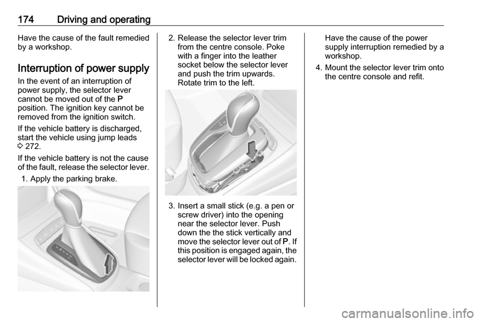
1. Apply the parking brake.2. Release the selector lever trim from the centre console. Poke
with a finger into the leather
socket below the selector lever
and push the trim upwards.
Rotate trim to the left.
3. Insert a small stick (e.g. a pen or screw driver) into the opening
near the selector lever. Push
down the the stick vertically and
move the selector lever out of P. If
this position is engaged again, the
selector lever will be locked again.
Have the cause of the power
supply interruption remedied by a
workshop.
4. Mount the selector lever trim onto
the centre console and refit.
Page 179 of 319

Driving and operating177The vehicle starts to move when the
brake pedal is released.
To start-off without depressing the
brake pedal, accelerate immediately
after engaging a gear as long as D or
R flashes.
If neither the accelerator nor the
brake pedal are depressed, no gear is engaged and D or R flashes for a
brief time in the display.
Stopping the vehicle
In D, first gear is engaged and the
clutch is released when the vehicle is
stopped. In R, reverse gear remains
engaged.
Engine braking
Automatic mode
When driving downhill, the manual
transmission automated does not shift into higher gears until a fairly
high engine speed has been reached. It shifts down in good time when
braking.Manual mode
To utilise the engine braking effect,
select a lower gear in good time when
driving downhill. Changing into
manual mode is only possible while the engine is running or during an
Autostop.
Rocking the vehicle
Rocking the vehicle is only
permissible if the vehicle is stuck in
sand, mud or snow. Move the selector
lever between R and D in a repeat
pattern. Do not race the engine and
avoid sudden acceleration.
Parking
The most recently engaged gear (see transmission display) remains
engaged when switching off ignition.
With N, no gear is engaged.
Therefore always apply the parking
brake when switching off ignition. If
parking brake is not applied, P flashes
in the transmission display and the
key cannot be removed from the
ignition switch. P stops flashing in the
transmission display as soon as the
parking brake is slightly applied.When the ignition is switched off, the
transmission no longer responds to
movement of the selector lever.
Emergency operation to avoid
freezing of the parking brake 3 165.
Manual mode
If a higher gear is selected when the
engine speed is too low, or a lower
gear when the speed is too high, the
shift is not executed. This prevents
the engine from running at too low or
too high an engine speed. A warning
message is displayed in the Driver
Information Centre. Vehicle
messages 3 123.
If engine speed is too low, the
transmission automatically shifts to a
lower gear.
When + or - is selected in automatic
mode, the transmission switches to
manual mode and shifts accordingly.
Gear shift indication
The symbol R or S with a number
beside is indicated when gearshifting
is recommended for fuel saving
reasons.
Page 229 of 319
Driving and operating227
Disengage and fold down the
connecting socket. Remove the
sealing plug from the opening for the
coupling ball bar and stow it.
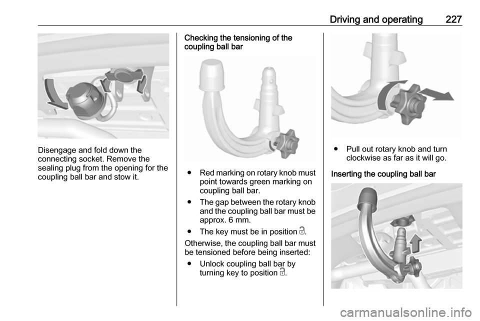
Checking the tensioning of the
coupling ball bar
● Red marking on rotary knob must
point towards green marking on
coupling ball bar.
● The gap between the rotary knob
and the coupling ball bar must be approx. 6 mm.
● The key must be in position c.
Otherwise, the coupling ball bar must be tensioned before being inserted:
● Unlock coupling ball bar by turning key to position c.
● Pull out rotary knob and turn
clockwise as far as it will go.
Inserting the coupling ball bar
Page 230 of 319
228Driving and operatingInsert the tensioned coupling ball bar
in the opening and push firmly
upwards until it audibly engages.
The rotary handle snaps back into its
original position resting against the
coupling ball bar without a gap.9 Warning
Do not touch rotary handle during
insertion.
Lock the coupling ball bar by turning
the key to position e. Remove the key
and close the protective flap.
Eye for break-away stopping cable
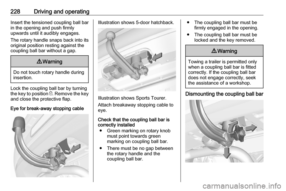
Illustration shows 5-door hatchback.
Illustration shows Sports Tourer.
Attach breakaway stopping cable to eye.
Check that the coupling ball bar is
correctly installed
● Green marking on rotary knob must point towards green
marking on coupling ball bar.
● There must be no gap between the rotary handle and the
coupling ball bar.
● The coupling ball bar must be firmly engaged in the opening.
● The coupling ball bar must be locked and the key removed.9Warning
Towing a trailer is permitted only
when a coupling ball bar is fitted correctly. If the coupling ball bardoes not engage correctly, seekthe assistance of a workshop.
Dismounting the coupling ball bar
Page 231 of 319
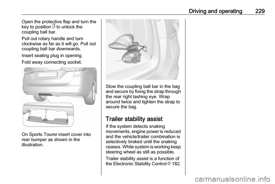
Driving and operating229Open the protective flap and turn the
key to position c to unlock the
coupling ball bar.
Pull out rotary handle and turn
clockwise as far as it will go. Pull out
coupling ball bar downwards.
Insert sealing plug in opening.
Fold away connecting socket.
On Sports Tourer insert cover into
rear bumper as shown in the
illustration.
Stow the coupling ball bar in the bag
and secure by fixing the strap through the rear right lashing eye. Wrap
around twice and tighten the strap to
secure the bag.
Trailer stability assist
If the system detects snaking
movements, engine power is reduced
and the vehicle/trailer combination is selectively braked until the snaking
ceases. While system is working keep
steering wheel as still as possible.
Trailer stability assist is a function of
the Electronic Stability Control 3 182.
Page 255 of 319
Vehicle care253No.Circuit17Body control module 618Body control module 319Data link connector20Airbag system21Climate control system22Central locking system, tailgate23Electronic key system24Power seat memory function25Airbag system steering wheel26Ignition switch/Steering column
lock27Body control module 228USB socket29–30Selector lever31Rear window wiper32Transmission control moduleNo.Circuit33Anti-theft alarm system/Power
sounder34Parking assist/Side blind spot
alert/Infotainment system/USB
socket35OnStar36Info display/Instrument cluster/ CD player37Infotainment system, radio
After having changed defective fuses,
close the fuse box cover and press
until it engages.
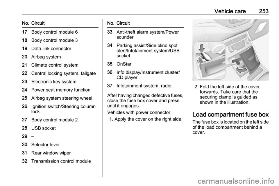
Vehicles with power connector: 1. Apply the cover on the right side.
2. Fold the left side of the cover forwards. Take care that the
securing clamp is guided as
shown in the illustration.
Load compartment fuse box
The fuse box is located on the left side
of the load compartment behind a
cover.
Page 302 of 319

300Customer informationCustomer
informationCustomer information ................300
Declaration of conformity .........300
REACH .................................... 304
Software acknowledgement ....304
Software update ......................306
Registered trademarks ............306
Vehicle data recording and pri‐
vacy ........................................... 307
Event data recorders ...............307
Radio Frequency Identification (RFID) ..................................... 310Customer information
Declaration of conformity
Radio transmission systems
This vehicle has systems that
transmit and / or receive radio waves
subject to Directive 2014/53/EU. The
manufacturers of the systems listed
below declare conformity with
Directive 2014/53/EU. The full text of
the EU declaration of conformity for each system is available at the
following internet address:
www.opel.com/conformity.
Importer is
Opel / Vauxhall, Bahnhofsplatz,
65423 Ruesselsheim am Main,
Germany.
Antenna
Laird
8100 Industrial Park Drive, Grand
Blanc, MI, 48439, USA
Operation frequency: N/A
Maximum output: N/AAntenna
Kathrein Automotive North America,
Inc.
3967 W. Hamlin Rd., Rochester Hills, MI 48309, USA
Operation frequency: N/A
Maximum output: N/A
Electronic key
Denso Coperation
Waldeckerstraße 11, 64546
Mörfelden-Walldorf, Germany
Operation frequency: 433,92 MHz
Maximum output: -5,88 dBm
Electronic key module
Denso Coperation
Waldeckerstraße 11, 64546
Mörfelden-Walldorf, Germany
Operation frequency: 125 kHz
Maximum output: -0,14 dBm
Front radar unit
Continental Automotive GmbH
ADC Automotive Distance Control
Systems GmbH, Peter-Dornier-
Straße 10, 88131 Lindau, Germany
Page 309 of 319

Customer information307EnGIS Technologies, Inc.
BringGo ®
is a registered trademark of
EnGIS Technologies, Inc.Google Inc.
Android™ and Google Play™ Store
are trademarks of Google Inc.Stitcher Inc.
Stitcher™ is a trademark of Stitcher,
Inc.Verband der Automobilindustrie e.V.
AdBlue ®
is a registered trademark of
the VDA.Vehicle data recording
and privacy
Event data recorders
Electronic control units are installed in
your vehicle. Control units process
data which is received by vehicle
sensors, for example, or which they
generate themselves or exchange
amongst themselves. Some control
units are necessary for the safe
functioning of your vehicle, others
assist you while you drive (driver
assistance systems), while others
provide comfort or infotainment
functions.
Operating data in the vehicle Control units process data for
operation of the vehicle.This data includes, for example:
● Vehicle status information (e.g. wheel rotation rate, speed,
movement delay, lateral
acceleration, "seatbelts
fastened" display),
● Ambient conditions (e.g. temperature, rain sensor,
distance sensor).
Most of this data is volatile and is
processed only in the vehicle itself,
and not beyond the operating time.
Moreover, many control units include
data storage device (amongst others the vehicle key). This is used to allow
information to be documented
temporarily or permanently on vehicle
condition, component stress,
maintenance requirements and
technical events and errors.
The following information, for
example, is stored:
● System component operating states (e.g. fill level, tyre
pressure, battery status),
● State of charge of the high voltage battery, estimated range(in the case of electric vehicles),