Parking function VAUXHALL ASTRA K 2020 User Guide
[x] Cancel search | Manufacturer: VAUXHALL, Model Year: 2020, Model line: ASTRA K, Model: VAUXHALL ASTRA K 2020Pages: 303, PDF Size: 27.35 MB
Page 173 of 303

Driving and operating171To reduce the operating forces ofthe parking brake, depress the
foot brake at the same time.
Control indicator R 3 109.
Electric parking brake
Applying when vehicle is stationary
Pull the switch m. If control indicator
m illuminates, electric parking brake
is applied.
The electric parking brake can always
be activated, even if the ignition is off.
Do not operate electric parking brake
system too often without engine
running as this will discharge the
vehicle battery.
Releasing
Switch on ignition. Keep foot brake
pedal depressed and then push
switch m. If control indicator m
extinguishes, electric parking brake is
released.
Drive away function
Vehicles with manual transmission:
Depressing the clutch pedal and then
slightly releasing the clutch pedal and slightly depressing the accelerator
pedal releases the electric parking brake automatically. This is not
possible when switch m is pulled at
the same time.
Vehicles with automatic transmission: Engaging D and then depressing the
accelerator pedal releases the
electric parking brake automatically.
This is not possible when switch m is
pulled at the same time.Dynamic braking when vehicle is
moving
When the vehicle is moving and the
switch m is kept pulled, the electric
parking brake system will decelerate
the vehicle, but will not apply
statically.
As soon as the switch m is released,
dynamic braking will be stopped.
Automatic applying
If the vehicle is equipped with
automatic transmission and adaptive cruise control is active, electric
parking brake is applied automatically when vehicle is stopped by the
system for more than 2 minutes.
Parking brake releases automatically
after moving off.
Functionality check
When the vehicle is not moving, the
electric parking brake might be
applied automatically. This is done to
check the system.
Page 179 of 303

Driving and operating177● The Traction Control system orElectronic Stability Control is
operating.
● Parking brake is applied.
● Simultaneous pressing RES/+
and brake pedal deactivates cruise control and will deletestored speed.
Resume stored speed Turn thumb wheel to RES/+ at a
speed above 20 mph. The stored
speed will be obtained.
Switching off the system
Press m, control indicator m in
instrument cluster extinguishes. The stored speed is deleted.
Pressing L to activate the speed
limiter or switching off the ignition also switches off cruise control and
deletes the stored speed.
Speed limiter
The speed limiter prevents the
vehicle exceeding a preset maximum
speed.The maximum speed can be set at
speeds above 15 mph up to
125 mph.
The driver can only accelerate up to
the preset speed. Deviations from the
limited speed may occur when driving downhill.
The preset speed limit is displayed in
the Driver Information Centre when
the system is active.
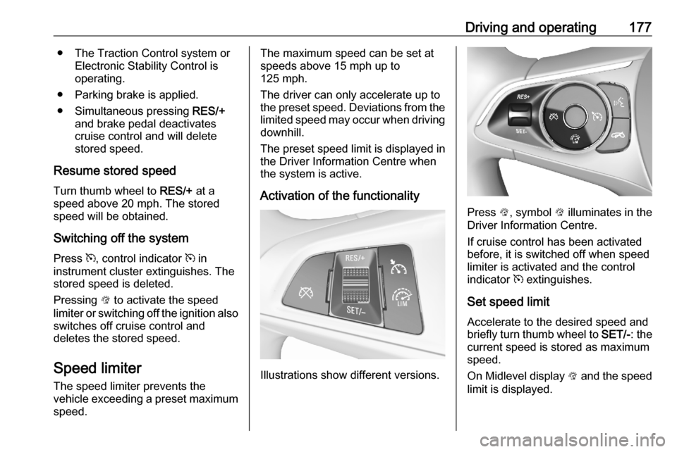
Activation of the functionality
Illustrations show different versions.
Press L, symbol L illuminates in the
Driver Information Centre.
If cruise control has been activated
before, it is switched off when speed
limiter is activated and the control
indicator m extinguishes.
Set speed limit
Accelerate to the desired speed and
briefly turn thumb wheel to SET/-: the
current speed is stored as maximum speed.
On Midlevel display L and the speed
limit is displayed.
Page 184 of 303

182Driving and operatingExample: If setting 3 (far) is selected,
then the driver is warned sooner
before a possible collision, also if
adaptive cruise control is inactive or
switched off.9 Warning
The Driver accepts full
responsibility to drive with the
appropriate following distance
based on traffic, weather, visibility
and regional regulation. Followingdistance must be adjusted or the
system switched off when required by the prevailing conditions.
Detecting the vehicle ahead
The green illuminated vehicle ahead
control indicator A is displayed when
the system detects a vehicle in the
driving path. The range of the sensors
is between 25 and 150 m depending
on vehicle speed.
Forward collision alert 3 186.
If this symbol does not display, or
displays briefly, adaptive cruise
control will not respond to vehicles
ahead.
Deactivation of the functionality
Adaptive cruise control is deactivated by the driver when:
● y is pressed.
● Brake pedal is applied.
● Clutch pedal is depressed for more than four seconds.
● Selector lever of automatic transmission is moved to N.
The system is also automatically
deactivated when:
● Vehicle speed accelerates above
120 mph or slows down below
15 mph. Vehicles with automatic
transmission slows down to a stop without deactivating within
5 minutes.● The Traction Control system is deactivated or operating.
● The Electronic Stability Control is
deactivated or operating.
● There is no traffic and nothing detected on the road sides for
approx. 1 minute. In this case
there are no radar echoes and
the sensor may report that it is
blocked.
● The active emergency braking system is applying the brakes.
● Driving on steep inclines.
● The radar sensor is blocked by an ice or water film.
● A fault is detected in the radar, camera, engine or brake system.
● The brakes need to cool down.
Additionally, the system is
automatically deactivated on vehicles with automatic transmission (full
speed range adaptive cruise control)
when:
● The incline uphill or downhill is greater than 20%.
● The electric parking brake is applied.
Page 192 of 303

190Driving and operatingEmergency automatic braking
After activation of brake preparation
system and just before the imminent
collision, this function automatically
applies limited braking to reduce the
impact speed of the collision or
prohibit a crash. Depending on the
situation, the vehicle may
automatically brake moderately or
hard. This front automatic braking can
only occur if a vehicle ahead is
detected, indicated by the vehicle
ahead indicator A 3 186.
If equipped only with front camera the
system operates up to a speed of
50 mph.
Below a speed of 25 mph the system
can apply full braking.
Emergency automatic braking may
slow the vehicle to a complete stop to try to avoid a potential crash. If this
happens, emergency automatic
braking may engage the electric
parking brake to hold the vehicle at a
stop. To release press the electric
parking brake button or firmly press
the accelerator pedal.9 Warning
Emergency automatic braking is
an emergency crash preparation
feature and is not designed to
avoid crashes. Do not rely on the
system to brake the vehicle.
Emergency automatic braking will
not brake outside of its operating speed range and only responds to
detected vehicles.
Forward looking brake assist
In addition to the brake preparation
system and emergency automatic
braking, the forward looking brake
assist function makes the brake assist more sensitive. Therefore, pressing
the brake pedal less strongly results
in immediate hard braking. This
function helps the driver brake
quicker and harder before the
imminent collision.
If equipped only with front camera the
system operates up to a speed of
52 mph.
9 Warning
Active emergency braking is not
designed to apply hard
autonomous braking or to
automatically avoid a collision. It is designed to reduce the vehicle
speed before a collision. It may not
react for pedestrians or animals.
After a sudden lane change, the
system needs a certain time to
detect the next preceding vehicle.
The complete attention of the
driver is always required while
driving. The driver shall always be ready to take action and apply the
brakes and steer to avoid
collisions. The system is designed to work with all occupants wearingtheir seat belts.
Intelligent Brake Assist
If the vehicle is equipped with radar
sensor Intelligent brake assist may
activate when the brake pedal is
applied quickly by providing a boost
to braking based on the speed of
approach and distance to a vehicle
ahead.
Page 200 of 303

198Driving and operating
Advanced parking assist is always
combined with front-rear parking assist. Both systems use the same
sensors in the front and rear bumper.
The system has six ultrasonic parking sensors each in both the rear and
front bumper.
Activation of advanced parking assist
Advanced parking assist can only be
activated when driving forwards.When searching for a parking slot, the system is ready to operate with a
short press of (.
The system recognises and
memorises 10 m for parallel parking
slots or 6 m for perpendicular parking
slots in the parking assist mode.
The system can only be activated and
searches for a parking slot at a speed
up to 18 mph.
The maximum allowed parallel
distance between the vehicle and a
row of parked cars is 150 cm.
FunctionalityParking slot searching mode,
indication in the Driver Information
Centre
Select parallel or perpendicular
parking slot in Driver Information
Centre by long press on (.
The system is configured to detect parking slots by default on the
passenger side. To detect parking
slots on the driver side, switch on the
turn lights on the driver side.
Page 205 of 303

Driving and operating203The system is deactivated if the
vehicle is towing a trailer or if a bike
carrier is attached.
Side blind spot alert is designed to
ignore stationary objects, e.g.
guardrails, posts, curbs, walls and
beams. Parked vehicles or oncoming
vehicles are not detected.
Fault
Occasional missed alerts can occur
under normal circumstances and will
increase in wet conditions.
Side blind spot alert does not operate when the left or right corners of the
rear bumper are covered with mud,
dirt, snow, ice, slush, or in heavy
rainstorms.
Cleaning instructions 3 266.
In the event of a fault in the system or if the system does not work due to
temporary conditions, the symbols in
the mirrors will be permanently
illuminated and a message is
displayed in the Driver Information
Centre. Seek the assistance of a
workshop.Rear view camera
The rear view camera assists the
driver when reversing by displaying a
view of the area behind the vehicle.
The view of the camera is displayed
in the Info Display.9 Warning
The rear view camera does not
replace driver vision. Note that
objects that are outside the
camera's field of view and the
parking assist sensors, e.g. below
the bumper or underneath the
vehicle, are not displayed.
Do not reverse or park the vehicle
using only the rear view camera.
Always check the surrounding of
the vehicle before driving.
Activation
Rear view camera is automatically
activated when reverse gear is
engaged.
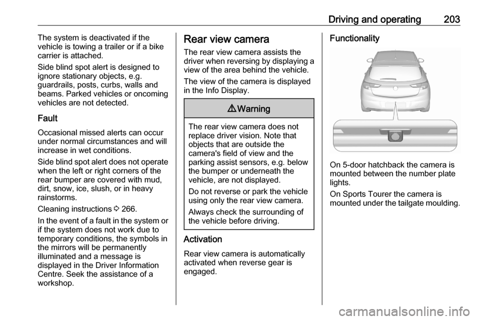
Functionality
On 5-door hatchback the camera is
mounted between the number plate
lights.
On Sports Tourer the camera is
mounted under the tailgate moulding.
Page 224 of 303

222Vehicle careCaution
When transporting the vehicle on
a train or on a recovery vehicle, the
mud flaps might be damaged.
Number plate mounting
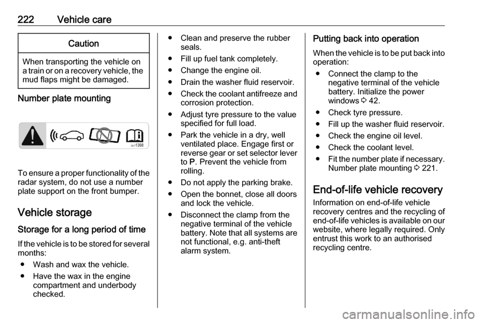
To ensure a proper functionality of the
radar system, do not use a number
plate support on the front bumper.
Vehicle storage Storage for a long period of timeIf the vehicle is to be stored for several
months:
● Wash and wax the vehicle.
● Have the wax in the engine compartment and underbody
checked.
● Clean and preserve the rubber seals.
● Fill up fuel tank completely.
● Change the engine oil.
● Drain the washer fluid reservoir.
● Check the coolant antifreeze and
corrosion protection.
● Adjust tyre pressure to the value specified for full load.
● Park the vehicle in a dry, well ventilated place. Engage first or
reverse gear or set selector lever
to P. Prevent the vehicle from
rolling.
● Do not apply the parking brake.
● Open the bonnet, close all doors and lock the vehicle.
● Disconnect the clamp from the negative terminal of the vehicle
battery. Note that all systems are
not functional, e.g. anti-theft
alarm system.Putting back into operation
When the vehicle is to be put back into
operation:
● Connect the clamp to the negative terminal of the vehicle
battery. Initialize the power
windows 3 42.
● Check tyre pressure.
● Fill up the washer fluid reservoir.
● Check the engine oil level.
● Check the coolant level.
● Fit the number plate if necessary.
Number plate mounting 3 221.
End-of-life vehicle recovery Information on end-of-life vehicle
recovery centres and the recycling of
end-of-life vehicles is available on our website, where legally required. Only
entrust this work to an authorised
recycling centre.
Page 246 of 303

244Vehicle careNo.Circuit17Body control module 418Body control module 319Data link connector20Airbag system21Climate control system22Central locking system / tailgate23Electronic key system24Power seat memory function25Airbag system steering wheel26Ignition switch / Steering
column lock27Body control module 228USB socket29Cigarette lighter / Power outlet
front30Selector lever31Rear window wiper32Transmission control moduleNo.Circuit33Anti-theft alarm system / Power
sounder34Parking assist / Side blind spot
alert / Infotainment system /
USB socket35SOS36Info Display / Instrument cluster37Infotainment system / radio
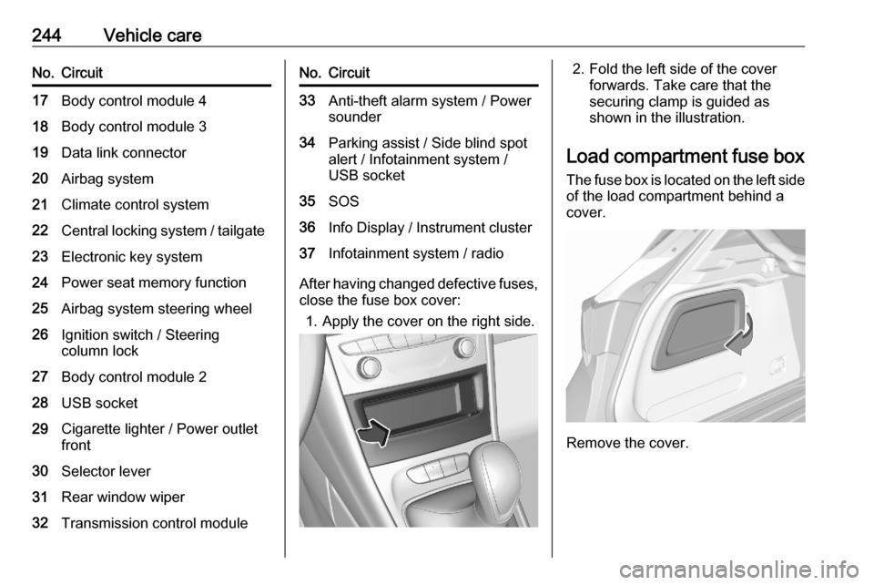
After having changed defective fuses,
close the fuse box cover:
1. Apply the cover on the right side.
2. Fold the left side of the cover forwards. Take care that thesecuring clamp is guided as
shown in the illustration.
Load compartment fuse box The fuse box is located on the left side
of the load compartment behind a
cover.
Remove the cover.
Page 253 of 303

Vehicle care251After inflating, some driving may be
required to update the tyre pressure
values in the Driver Information
Centre. During this time w may
illuminate.
If w illuminates at lower temperatures
and extinguishes after driving, this
could be an indicator for approaching
a low tyre pressure condition. Check
tyre pressure.
Vehicle messages 3 121.
If the tyre pressure must be reduced
or increased, switch off ignition.
Only mount wheels with pressure
sensors, otherwise the tyre pressure
will not be displayed and w
illuminates continuously.
A spare wheel or temporary spare
wheel is not equipped with pressure
sensors. The tyre pressure
monitoring system is not operational
for these tyres. Control indicator w
illuminates. For the further three
tyres, the system remains
operational.The use of commercially-available
liquid tyre repair kits can impair the
function of the system. Factory-
approved repair kits can be used.
Operating electronic devices or being close to facilities using similar wave
frequencies could disrupt the tyre
pressure monitoring system.
Each time the tyres are replaced, tyre pressure monitoring system sensors
must be dismounted and serviced.
For the screwed sensor, replace
valve core and sealing ring. For the
clipped sensor, replace complete
valve stem.
Use only original plastic valve caps to
protect valve on any damage.Caution
Do not use metal valve caps as
they lead to valve oxidation and
damage.
Vehicle loading status
Adjust tyre pressure to load condition
according to the tyre information label or tyre pressure chart 3 283, and
select the appropriate setting in Tyre
Load within the Vehicle Information
Menu 3 114. This setting determines
the reference pressures for the tyre
pressure warnings.
The Tyre Load menu only appears
when the vehicle is at a standstill and the parking brake is applied. On
vehicles with automatic transmission
the selector lever must be in P.
Midlevel display:
Select the Tyre load page under the
Vehicle Information Menu ? in the
Driver Information Centre 3 114.
Page 300 of 303

298Headlights when driving abroad 132
Head restraint adjustment .............8
Head restraints ............................ 47
Heated mirrors ............................. 40
Heated rear window ..................... 44
Heated steering wheel .................92
Heated windscreen .......................44
Heating .................................. 55, 57
High beam ......................... 112, 132
High beam assist ................112, 130
Hill start assist ........................... 172
Horn ....................................... 13, 93
I Identification plate .....................274
Ignition switch positions .............151
Immobiliser .......................... 39, 112
Indicators .................................... 103
Inductive charging ........................99
Info Display ................................. 120
Information displays.................... 114
Instrument cluster ......................100
Instrument panel fuse box .........243
Instrument panel illumination control .................................... 136
Instrument panel overview ........... 10
Interior care ............................... 268
Interior lighting ............................ 136
Interior lights ...................... 137, 239
Interior mirrors .............................. 41Interruption of power supply ......168
Introduction .................................... 3
J
Jump starting ............................. 262
K Key, memorised settings ..............24
Keys ............................................. 20
Keys, locks ................................... 20
L
Lane keep assist ................110, 209
Lashing eyes ............................... 82
LED headlights ...................112, 133
Lighting features .........................138
Light switch ................................ 129
Load compartment ................31, 74
Load compartment cover .............80
Load compartment fuse box ......244
Loading information .....................89
Low fuel ..................................... 112
M Malfunction indicator light ..........109
Manual anti-dazzle ......................41
Manual mode ............................. 167
Manual seat adjustment ...............49
Manual transmission .................. 169
Manual windows ..........................42
Massage ....................................... 56Maximum speed......................... 248
Memorised settings ......................24
Mirror adjustment ........................... 9
Misted light covers .....................136
N
New vehicle running-in ..............151
Number plate light .....................239
O Object detection systems ...........194
Odometer ................................... 104
Oil, engine .......................... 271, 275
Outside temperature ....................96
Overrun cut-off ........................... 156
P Parking ................................ 18, 159
Parking assist ............................ 194
Parking brake ............................ 170
Parking lights ............................. 136
Particulate filter ........................... 161
Pedestrian detection ...................113
Performance .............................. 279
Performing work ........................223
Power button .............................. 152
Power outlets ............................... 98
Power seat adjustment ................51
Power windows ............................ 42
Preheating ................................. 111
Puncture ..................................... 258