steering lock VAUXHALL ASTRA K 2020 User Guide
[x] Cancel search | Manufacturer: VAUXHALL, Model Year: 2020, Model line: ASTRA K, Model: VAUXHALL ASTRA K 2020Pages: 303, PDF Size: 27.35 MB
Page 155 of 303

Driving and operating153preheating. Control indicators
illuminate and most electrical
functions are operable.Engine start
Press Engine Start/Stop briefly while:
● manual transmission: operating clutch pedal,
● automatic transmission: operating brake pedal with
selector lever in P or N.
Starting the engine 3 154.Ignition off
Press Engine Start/Stop briefly when
Autostop is activated or when engine is running and vehicle is stationary.
Automatic transmission: apply the
parking brake and engage P.
Press Engine Start/Stop briefly
without operating clutch or brake pedal when in ignition on power
mode.
Some functions remain active until
driver's door is opened, provided the
ignition was on previously.Emergency shut off during driving
Press Engine Start/Stop for longer
than 2 seconds or press twice briefly
within 5 seconds 3 154.
Steering wheel lock The steering wheel lock activates
automatically when:
● The vehicle is stationary.
● The ignition has been switched off.
● The driver's door is opened.
To release steering wheel lock, open
and close driver's door and switch on accessory mode or start the engine
directly.9 Warning
If the vehicle battery is discharged,
the vehicle must not be towed,
tow-started or jump-started as the
steering wheel lock cannot be
disengaged.
Operation on vehicles with
electronic key system in case of
failure
If either the electronic key fails or the
battery of the electronic key is weak,
the Driver Information Centre may
display No Remote Detected or
Replace Battery in Remote Key when
you try to start the vehicle.
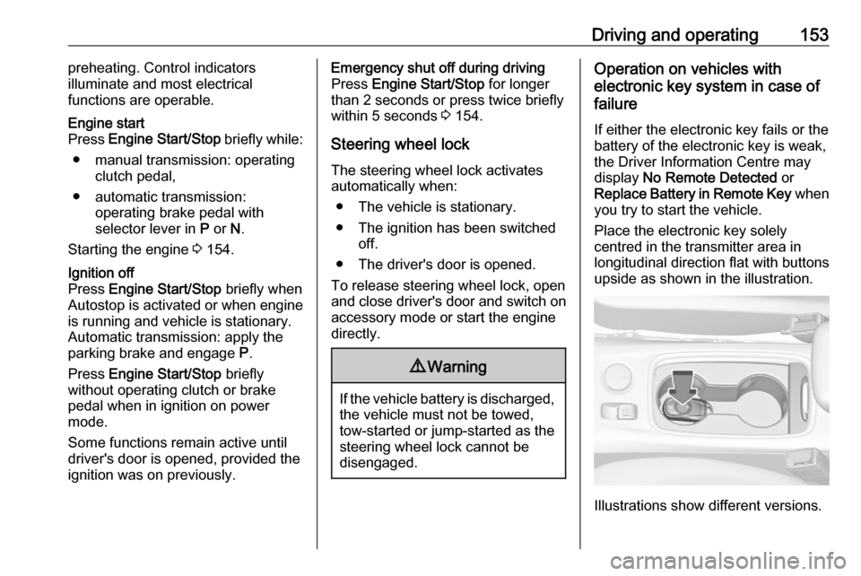
Place the electronic key solely
centred in the transmitter area in
longitudinal direction flat with buttons
upside as shown in the illustration.
Illustrations show different versions.
Page 156 of 303

154Driving and operating
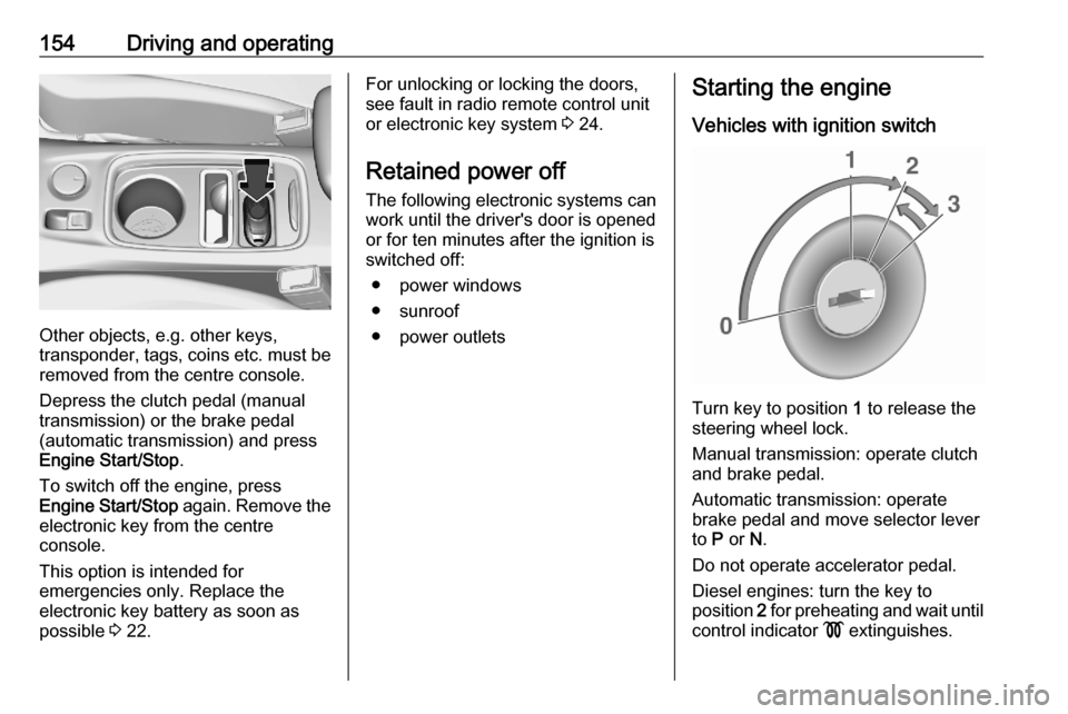
Other objects, e.g. other keys,
transponder, tags, coins etc. must be removed from the centre console.
Depress the clutch pedal (manual
transmission) or the brake pedal
(automatic transmission) and press
Engine Start/Stop .
To switch off the engine, press
Engine Start/Stop again. Remove the
electronic key from the centre
console.
This option is intended for
emergencies only. Replace the
electronic key battery as soon as
possible 3 22.
For unlocking or locking the doors,
see fault in radio remote control unit
or electronic key system 3 24.
Retained power off
The following electronic systems can
work until the driver's door is opened
or for ten minutes after the ignition is
switched off:
● power windows
● sunroof
● power outletsStarting the engine
Vehicles with ignition switch
Turn key to position 1 to release the
steering wheel lock.
Manual transmission: operate clutch
and brake pedal.
Automatic transmission: operate
brake pedal and move selector lever
to P or N.
Do not operate accelerator pedal.
Diesel engines: turn the key to
position 2 for preheating and wait until
control indicator ! extinguishes.
Page 162 of 303

160Driving and operatinglever to position P before
removing the ignition key or
switching off ignition on
vehicles with power button. On
an uphill slope, turn the front
wheels away from the kerb.
If the vehicle is on a downhill
slope, engage reverse gear or
set the selector lever to position
P before removing the ignition
key or switching off ignition on
vehicles with power button.
Turn the front wheels towards
the kerb.
● Close the windows and the sunroof.
● Remove the ignition key from the ignition switch or switch off
ignition on vehicles with power
button. Turn the steering wheel until the steering wheel lock is
felt to engage.
For vehicles with automatic
transmission, the key can only
be removed when the selector
lever is in position P.● Lock the vehicle by pressing the
button on the door handle or the
button e on the remote control.
● Activate the anti-theft alarm system.
● The engine cooling fans may run
after the engine has been
switched off 3 223.Caution
After running at high engine
speeds or with high engine loads,
operate the engine briefly at a low load or run in neutral for
approx. 30 seconds before
switching off, in order to protect
the turbocharger.
Notice
In the event of an accident with airbag deployment, the engine is
switched off automatically if the
vehicle comes to a standstill within a
certain time.
In countries with extreme cold
temperatures it may be necessary to
park the vehicle without applied
parking brake. Make sure to park the
vehicle on a level surface.
Page 190 of 303

188Driving and operatingThe complete attention of the
driver is always required while
driving. The driver must always be ready to take action and apply the
brakes.
System limitations
Forward collision alert is designed to
warn on vehicles only, but may react
also to other objects.
In the following cases, forward
collision alert may not detect a vehicle
ahead or sensor performance is
limited:
● driving on winding or hilly roads● during nighttime driving
● weather limits visibility, such as fog, rain, or snow
● the sensor in the windscreen is blocked by snow, ice, slush, mud,dirt, windscreen damage or
affected by foreign items, e.g.
stickers
Following distance
indication
The following distance indication
displays the distance to a preceding
moving vehicle. The front camera in
the windscreen and the Radar sensor
are used to detect the distance of a
vehicle directly ahead in the vehicle's path. It is active at speeds above
25 mph.
When a preceding vehicle is detected
ahead, the distance is indicated in
seconds, displayed on a page in the
Driver Information Centre.
On Midlevel display, choose Info
Menu ? via MENU on the indicator
lever and turn the adjuster wheel to
choose following distance indication
page 3 114
On Uplevel display, select Info menu
via steering wheel buttons and press
o to select following distance
indication 3 114.
The minimum indicated distance is 0.5 seconds.
If there is no vehicle ahead or the vehicle ahead is out of range, two
dashes will be displayed: -.- sec.
Page 244 of 303

242Vehicle careNo.Circuit16Fuel injection17Fuel injection18Diesel exhaust system19–20–21–22ABS23Washer system for windscreen
and rear window24–25Diesel fuel heating26Transmission control module27Power tailgate module28–29Heated rear window30Mirror defrost31–No.Circuit32DC transformer / LED display /
Electrical heater / Climate
control / Glow plug controller33–34Horn35Engine control module36Right high beam (Halogen, Eco
LED) / Right low beam (LED)37Left high beam (Halogen, Eco
LED)38LED headlight / Automatic
headlight range adjustment39Front fog light40Central Gateway Module41–42Manual headlight range adjust‐
ment43Fuel pump44Rear view camera / Inside rear
view mirror / Trailer moduleNo.Circuit45LED headlight left / Automatic
headlight range adjustment left46Instrument cluster47Steering column lock48Rear wiper49Outside rearview mirror50LED headlight right / Automatic
headlight range adjustment
right51Left low beam (LED)52Engine control module / Trans‐
mission control module53Windscreen wiper54Windscreen wiper55Diesel Exhaust system56–57–
After having changed defective fuses,
close the fuse box cover and press
until it engages.
Page 246 of 303

244Vehicle careNo.Circuit17Body control module 418Body control module 319Data link connector20Airbag system21Climate control system22Central locking system / tailgate23Electronic key system24Power seat memory function25Airbag system steering wheel26Ignition switch / Steering
column lock27Body control module 228USB socket29Cigarette lighter / Power outlet
front30Selector lever31Rear window wiper32Transmission control moduleNo.Circuit33Anti-theft alarm system / Power
sounder34Parking assist / Side blind spot
alert / Infotainment system /
USB socket35SOS36Info Display / Instrument cluster37Infotainment system / radio
After having changed defective fuses,
close the fuse box cover:
1. Apply the cover on the right side.
2. Fold the left side of the cover forwards. Take care that thesecuring clamp is guided as
shown in the illustration.
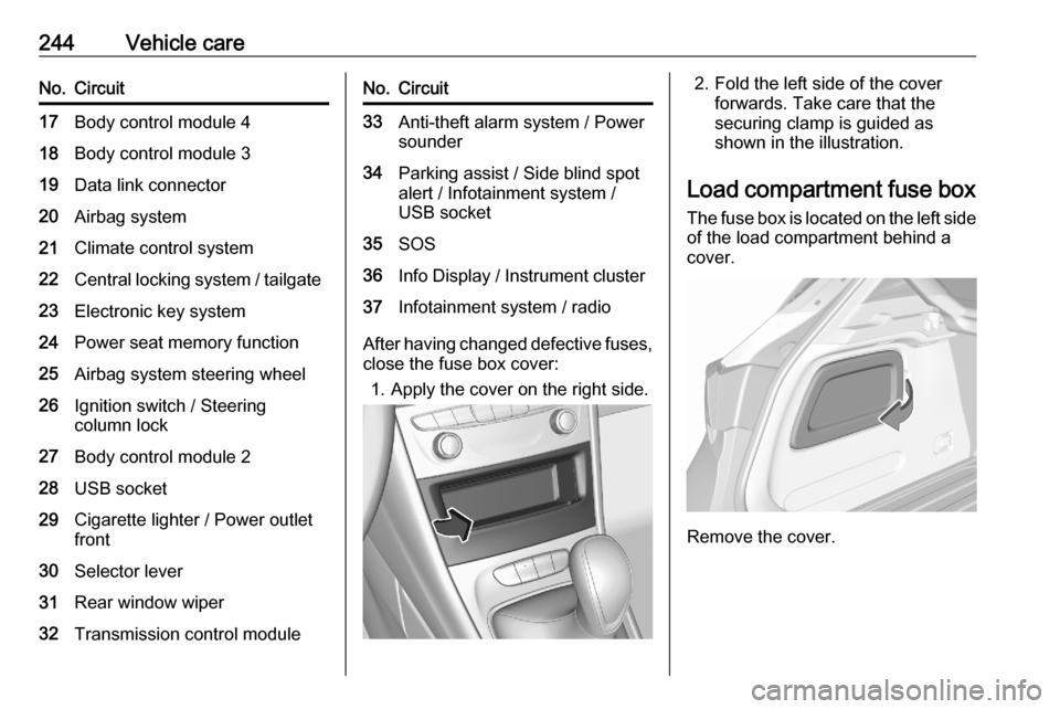
Load compartment fuse box The fuse box is located on the left side
of the load compartment behind a
cover.
Remove the cover.
Page 256 of 303

254Vehicle careTyre chains
Tyre chains are only permitted on the
front wheels.
Always use fine mesh chains that add no more than 10 mm to the tyre tread
and the inboard sides (including chain lock).
9 Warning
Damage may lead to tyre blowout.
Tyre chains are permitted on tyres of
size 195/65 R15, 205/55 R16 and
215/55 R16.
Temporary spare wheel
The use of tyre chains is not permitted on the temporary spare wheel.
Tyre repair kit Minor damage to the tyre tread can be
repaired with the tyre repair kit.
Do not remove foreign bodies from
the tyres.
Tyre damage exceeding 4 mm or that is at tyre's sidewall cannot be repairedwith the tyre repair kit.9 Warning
Do not drive faster than 50 mph.
Do not use for a lengthy period.
Steering and handling may be
affected.
If vehicle has a flat tyre:
Apply the parking brake and engage
first gear, reverse gear or P.
On 5-door hatchback the tyre repair
kit is on the right side in the load
compartment behind a cover.
Page 266 of 303

264Vehicle careRoute the leads so that they cannot
catch on rotating parts in the engine
compartment.
To start the engine: 1. Start the engine of the vehicle providing the jump.
2. After 5 minutes, start the other engine. Start attempts should be
made for no longer than
15 seconds at an interval of one
minute.
3. Allow both engines to idle for approx. 3 minutes with the leads
connected.
4. Switch on electrical consumers (e.g. headlights, heated rear
window) of the vehicle receiving
the jump start.
5. Reverse above sequence exactly when removing leads.Towing
Towing the vehicle
Wrap a cloth around the tip of a flat
screwdriver to prevent paint damage. Insert the screwdriver in the slot at the
edge of the cap. Release the cap by
levering it out carefully.
The towing eye is stowed with the
vehicle tools 3 246.
Screw in the towing eye as far as it will
go until it stops in a horizontal
position.
Attach a tow rope – or better still a tow
rod – to the towing eye.
The towing eye must only be used for
towing and not for recovering the
vehicle.
Switch on ignition to release steering wheel lock and to permit operation of
brake lights, horn and windscreen
wiper.
Page 300 of 303

298Headlights when driving abroad 132
Head restraint adjustment .............8
Head restraints ............................ 47
Heated mirrors ............................. 40
Heated rear window ..................... 44
Heated steering wheel .................92
Heated windscreen .......................44
Heating .................................. 55, 57
High beam ......................... 112, 132
High beam assist ................112, 130
Hill start assist ........................... 172
Horn ....................................... 13, 93
I Identification plate .....................274
Ignition switch positions .............151
Immobiliser .......................... 39, 112
Indicators .................................... 103
Inductive charging ........................99
Info Display ................................. 120
Information displays.................... 114
Instrument cluster ......................100
Instrument panel fuse box .........243
Instrument panel illumination control .................................... 136
Instrument panel overview ........... 10
Interior care ............................... 268
Interior lighting ............................ 136
Interior lights ...................... 137, 239
Interior mirrors .............................. 41Interruption of power supply ......168
Introduction .................................... 3
J
Jump starting ............................. 262
K Key, memorised settings ..............24
Keys ............................................. 20
Keys, locks ................................... 20
L
Lane keep assist ................110, 209
Lashing eyes ............................... 82
LED headlights ...................112, 133
Lighting features .........................138
Light switch ................................ 129
Load compartment ................31, 74
Load compartment cover .............80
Load compartment fuse box ......244
Loading information .....................89
Low fuel ..................................... 112
M Malfunction indicator light ..........109
Manual anti-dazzle ......................41
Manual mode ............................. 167
Manual seat adjustment ...............49
Manual transmission .................. 169
Manual windows ..........................42
Massage ....................................... 56Maximum speed......................... 248
Memorised settings ......................24
Mirror adjustment ........................... 9
Misted light covers .....................136
N
New vehicle running-in ..............151
Number plate light .....................239
O Object detection systems ...........194
Odometer ................................... 104
Oil, engine .......................... 271, 275
Outside temperature ....................96
Overrun cut-off ........................... 156
P Parking ................................ 18, 159
Parking assist ............................ 194
Parking brake ............................ 170
Parking lights ............................. 136
Particulate filter ........................... 161
Pedestrian detection ...................113
Performance .............................. 279
Performing work ........................223
Power button .............................. 152
Power outlets ............................... 98
Power seat adjustment ................51
Power windows ............................ 42
Preheating ................................. 111
Puncture ..................................... 258