ESP VAUXHALL CASCADA 2014 Owner's Guide
[x] Cancel search | Manufacturer: VAUXHALL, Model Year: 2014, Model line: CASCADA, Model: VAUXHALL CASCADA 2014Pages: 247, PDF Size: 7.34 MB
Page 153 of 247
Driving and operating151
dynamic vehicle condition and
changes the settings for suspension
to SPORT mode to increase vehicle
stability.
When the driving characteristic or the
dynamic vehicle state returns to the
former state, DMC will change the
settings to the preselected driving
mode.
Personalised settings in the
SPORT mode The driver can select the functions of
the SPORT mode when SPORT
button is pressed. These settings can
be changed in the menu Settings in
the Info-Display. Vehicle
personalisation 3 102.Driver assistance
systems9 Warning
Driver assistance systems are
developed to support the driver
and not to replace his attention.
The driver accepts full
responsibility when driving the
vehicle.
When using driver assistance
systems, always take care
regarding the current traffic
situation.
Cruise control
The cruise control can store and
maintain speeds of approx. 20 to
120 mph. Deviations from the stored
speeds may occur when driving uphill or downhill.
For safety reasons the cruise control cannot be activated until the foot
brake has been operated once.
Activating in first gear is not possible.
Do not use the cruise control if it is not advisable to maintain a constant
speed.
With automatic transmission, only
activate cruise control in automatic
mode.
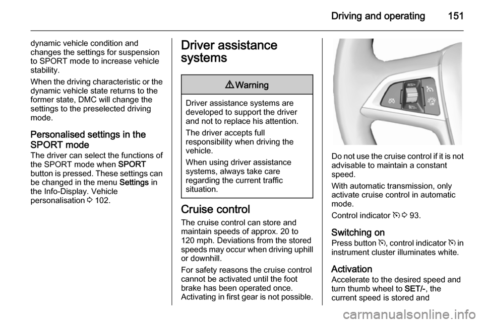
Control indicator m 3 93.
Switching on
Press button m, control indicator m in
instrument cluster illuminates white.
Activation
Accelerate to the desired speed and
turn thumb wheel to SET/-, the
current speed is stored and
Page 156 of 247
154Driving and operating
The limited speed will flash in the
Driver Information Centre and,
depending on the vehicle, additionally
a chime sounds during this period.
Release the accelerator pedal andthe speed limiter function is
reactivated once a speed lower than
the limit speed is obtained.
Deactivation
Press button y: speed limiter is
deactivated and the vehicle can be
driven without speed limit.
The limited speed is stored and a
corresponding message appears in
the Driver Information Centre.
Resume limit speedTurn thumb wheel to RES/+. The
stored speed limit will be obtained.
Switching off
Press button L, the speed limit
indication in the Driver Information Centre extinguishes. The stored
speed is deleted.By pressing button m to activate
cruise control or by switching off the
ignition, speed limiter is also
deactivated and the stored speed is
deleted.
Forward collision alert The forward collision alert can help to
avoid or reduce the harm caused by
front-end crashes. If a vehicle directly
ahead is approached too quickly, a
warning chime and alert in the Driver
Information Centre is provided.
Forward collision alert uses the front
camera system in the windscreen to
detect a vehicle directly ahead, in
your path, within a distance of approx. 60 metres.
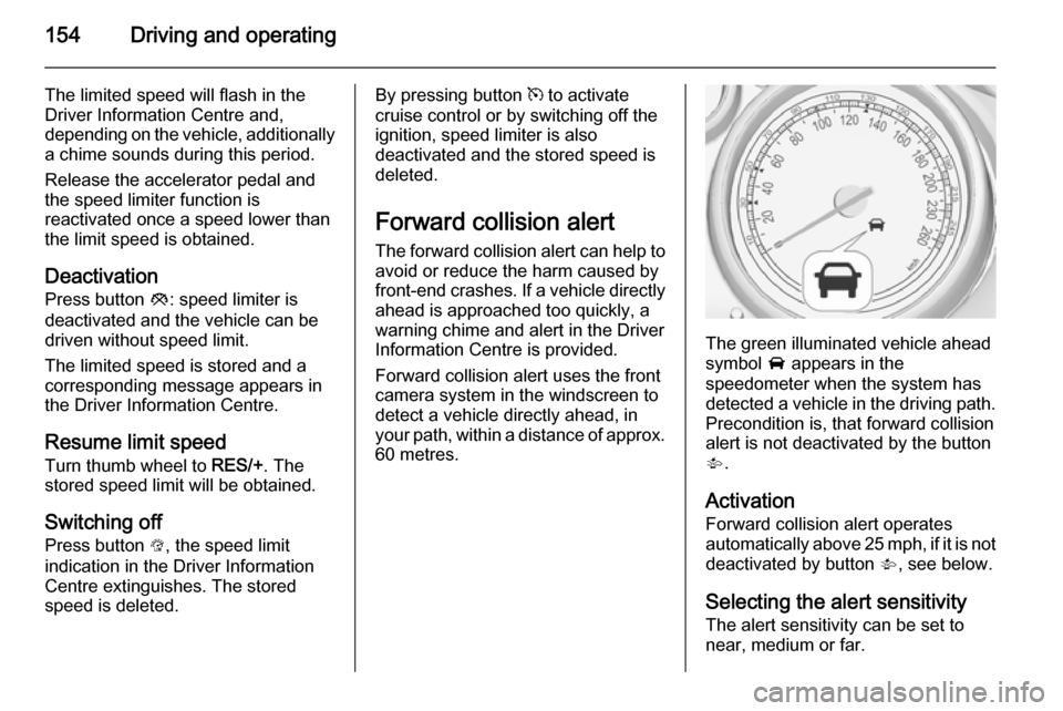
The green illuminated vehicle ahead
symbol A appears in the
speedometer when the system has
detected a vehicle in the driving path.
Precondition is, that forward collision
alert is not deactivated by the button
V .
Activation Forward collision alert operates
automatically above 25 mph, if it is not
deactivated by button V, see below.
Selecting the alert sensitivity
The alert sensitivity can be set to
near, medium or far.
Page 157 of 247
Driving and operating155
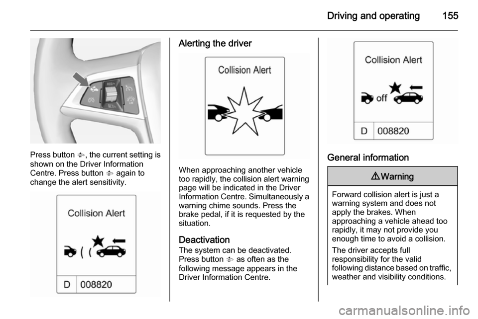
Press button V, the current setting is
shown on the Driver Information
Centre. Press button V again to
change the alert sensitivity.
Alerting the driver
When approaching another vehicle
too rapidly, the collision alert warning page will be indicated in the Driver
Information Centre. Simultaneously a
warning chime sounds. Press the
brake pedal, if it is requested by the
situation.
Deactivation
The system can be deactivated.
Press button V as often as the
following message appears in the
Driver Information Centre.
General information
9 Warning
Forward collision alert is just a
warning system and does not
apply the brakes. When
approaching a vehicle ahead too
rapidly, it may not provide you
enough time to avoid a collision.
The driver accepts full
responsibility for the valid
following distance based on traffic,
weather and visibility conditions.
Page 158 of 247
156Driving and operatingThe complete attention of the
driver is always required while
driving. He shall always be ready
to take action and apply the
brakes.
System limitations
The system is designed to warn only for vehicles, but may react also on
other objects.
In the following cases, forward
collision alert may not detect a vehicle ahead or sensor performance is
limited:
■ on winding roads,
■ when weather limits visibility, such as fog, rain, or snow,
■ when the sensor is blocked by snow, ice, slush, mud, dirt, or
windscreen damage.
Following distance
indication
The following distance indication
displays the distance to a preceding
moving vehicle. The front camera in
the windscreen is used to detect the
distance of a vehicle directly ahead in
the vehicle's path. It is active at
speeds above 25 mph.
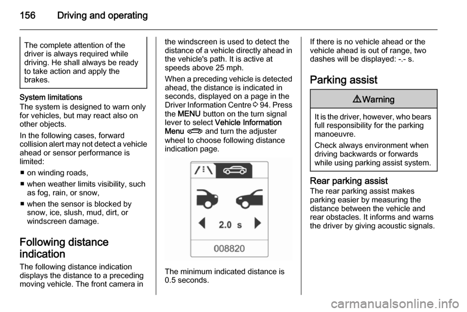
When a preceding vehicle is detected
ahead, the distance is indicated in
seconds, displayed on a page in the
Driver Information Centre 3 94 . Press
the MENU button on the turn signal
lever to select Vehicle Information
Menu X and turn the adjuster
wheel to choose following distance
indication page.
The minimum indicated distance is
0.5 seconds.
If there is no vehicle ahead or the vehicle ahead is out of range, two
dashes will be displayed: -.- s.
Parking assist9 Warning
It is the driver, however, who bears
full responsibility for the parking
manoeuvre.
Check always environment when
driving backwards or forwards
while using parking assist system.
Rear parking assist
The rear parking assist makes
parking easier by measuring the
distance between the vehicle and
rear obstacles. It informs and warns
the driver by giving acoustic signals.
Page 161 of 247
Driving and operating159
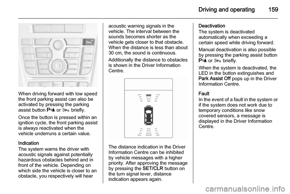
When driving forward with low speed
the front parking assist can also be
activated by pressing the parking
assist button r or D briefly.
Once the button is pressed within an
ignition cycle, the front parking assist
is always reactivated when the
vehicle underruns a certain value.
Indication
The system warns the driver with
acoustic signals against potentially
hazardous obstacles behind and in
front of the vehicle. Depending on
which side the vehicle is closer to an
obstacle, you respectively will hear
acoustic warning signals in the
vehicle. The interval between the
sounds becomes shorter as the
vehicle gets closer to that obstacle.
When the distance is less than about 30 cm, the sound is continuous.
Additionally the distance to obstacles
is shown in the Driver Information
Centre.
The distance indication in the Driver
Information Centre can be inhibited
by vehicle messages with a higher
priority. After approving the message
by pressing the SET/CLR button on
the turn signal lever, distance
indication appears again.
Deactivation
The system is deactivated
automatically when exceeding a
certain speed while driving forward.
Manual deactivation is also possible
by pressing the parking assist button
r or D briefly.
When the system is deactivated, the
LED in the button extinguishes and
Park Assist Off pops up in the Driver
Information Centre.
Fault
In the event of a fault in the system or if the system does not work due to
temporary conditions like snow
covered sensors, a message is
displayed in the Driver Information
Centre.
Page 165 of 247
Driving and operating163
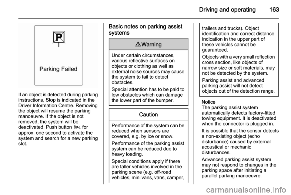
If an object is detected during parkinginstructions, Stop is indicated in the
Driver Information Centre. Removing
the object will resume the parking
manoeuvre. If the object is not
removed, the system will be
deactivated. Push button D for
approx. one second to activate the
system and search for a new parking
slot.
Basic notes on parking assist
systems9 Warning
Under certain circumstances,
various reflective surfaces on
objects or clothing as well as
external noise sources may cause the system to fail to detect
obstacles.
Special attention has to be paid to
low obstacles which can damage
the lower part of the bumper.
Caution
Performance of the system can be reduced when sensors are
covered, e.g. by ice or snow.
Performance of the parking assist
system can be reduced due to
heavy loading.
Special conditions apply if there
are taller vehicles involved in the
parking scene (e.g. off-road
vehicles, mini vans, vans, camper,
trailers and trucks). Object
identification and correct distance
indication in the upper part of
these vehicles cannot be
guaranteed.
Objects with a very small reflection
cross section, like objects of
narrow size or soft materials, may
not be detected by the system.
Parking assist and advanced
parking assist will not detect
objects out of the detection range.
Notice
The parking assist system
automatically detects factory-fitted
towing equipment. It is deactivated
when the connector is plugged in.
It is possible that the sensor detects a non-existing object (echo
disturbance) caused by external
acoustical or mechanic
disturbances.
Advanced parking assist system
may not respond to changes in the
parking space after initiating a
parallel parking manoeuvre.
Page 172 of 247
170Driving and operating
FaultThe traffic sign assistant system may
not operate correctly when:
■ the area of the windscreen, where the front camera is located, is notclean
■ traffic signs are completely or partially covered or difficult to
discern
■ there are adverse environmental conditions, e.g. heavy rain, snow,
direct sunlight or shadows. In this
case No Traffic Sign Detection due
to Weather is indicated on the
display
■ traffic signs are incorrectly mounted
or damaged
■ traffic signs do not comply with the Vienna Convention on traffic signs
(Wiener Übereinkommen über
Straßenverkehrszeichen)Caution
The system is intended to help the driver within a defined speed
range to discern certain traffic
signs. Do not ignore traffic signs
which are not displayed by the
system.
The system does not discern any other than the conventional traffic
signs that might give or end a
speed limit.
Do not let this special feature
tempt you into taking risks when
driving.
Always adapt speed to the road
conditions.
The driver assistance systems do not relieve the driver from full
responsibility for vehicle
operation.
Lane departure warning
The lane departure warning systemobserves the lane markings between
which the vehicle is driving via a front camera. The system detects lane
changes and warns the driver in the
event of an unintended lane change
via visual and acoustic signals.
Criteria for the detection of an
unintended lane change are:
■ no operation of turn signals
■ no brake pedal operation
■ no active accelerator operation or speeding-up
■ no active steering
If the driver is performing these
actions, no warning will be issued.
Activation
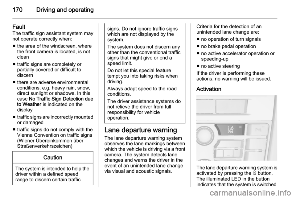
The lane departure warning system isactivated by pressing the ) button.
The illuminated LED in the button
indicates that the system is switched
Page 177 of 247

Driving and operating175Trailer towingTrailer loads
The permissible trailer loads are
vehicle and engine-dependent
maximum values which must not be
exceeded. The actual trailer load is
the difference between the actual
gross weight of the trailer and the
actual coupling socket load with the
trailer coupled.
The permissible trailer loads are
specified in the vehicle documents. In general, they are valid for gradients
up to max. 12 %.
The permitted trailer load applies up
to the specified incline and up to an
altitude of 1000 metres above sea
level. Since engine power decreases
as altitude increases due to the air
becoming thinner, therefore reducing
climbing ability, the permissible gross
train weight also decreases by 10 %
for every 1000 metres of additional
altitude. The gross train weight does
not have to be reduced when driving
on roads with slight inclines (less than
8 %, e.g. motorways).The permissible gross train weight
must not be exceeded. This weight is specified on the identification plate3 226.
Vertical coupling load
The vertical coupling load is the load
exerted by the trailer on the coupling
ball. It can be varied by changing the
weight distribution when loading the
trailer.
The maximum permissible vertical
coupling load (75 kg) is specified on
the towing equipment identification
plate and in the vehicle documents.
Always aim for the maximum load,
especially in the case of heavy
trailers. The vertical coupling load
should never fall below 25 kg.Rear axle load
When the trailer is coupled and the
towing vehicle fully loaded, the
permissible rear axle load (see
identification plate or vehicle
documents) may be exceeded by
100 kg, the gross vehicle weight
rating may be exceeded by 100 kg. If
the permissible rear axle load is
exceeded, a maximum speed of
60 mph applies.
Towing equipmentCaution
When operating without a trailer,
remove the coupling ball bar.
Stowage of coupling ball bar
The coupling ball bar is stowed in a
bag and must be secured in the load
compartment.
Page 185 of 247
Vehicle care183
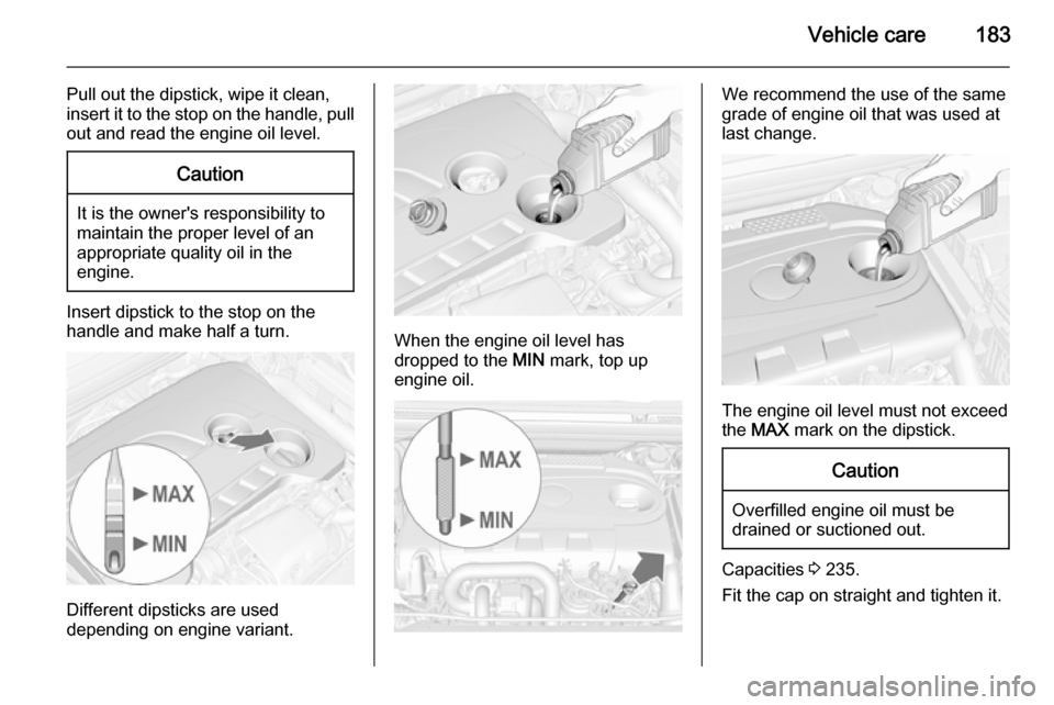
Pull out the dipstick, wipe it clean,
insert it to the stop on the handle, pull
out and read the engine oil level.Caution
It is the owner's responsibility to
maintain the proper level of an
appropriate quality oil in the
engine.
Insert dipstick to the stop on the
handle and make half a turn.
Different dipsticks are used
depending on engine variant.
When the engine oil level has
dropped to the MIN mark, top up
engine oil.
We recommend the use of the same
grade of engine oil that was used at
last change.
The engine oil level must not exceed
the MAX mark on the dipstick.
Caution
Overfilled engine oil must be
drained or suctioned out.
Capacities 3 235.
Fit the cap on straight and tighten it.
Page 198 of 247
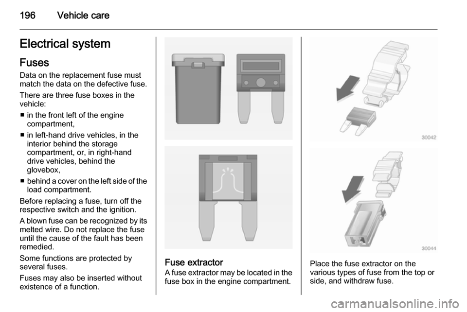
196Vehicle careElectrical systemFuses
Data on the replacement fuse must
match the data on the defective fuse.
There are three fuse boxes in the
vehicle:
■ in the front left of the engine compartment,
■ in left-hand drive vehicles, in the interior behind the storage
compartment, or, in right-hand
drive vehicles, behind the
glovebox,
■ behind a cover on the left side of the
load compartment.
Before replacing a fuse, turn off the
respective switch and the ignition.
A blown fuse can be recognized by its melted wire. Do not replace the fuse
until the cause of the fault has been
remedied.
Some functions are protected by
several fuses.
Fuses may also be inserted without existence of a function.
Fuse extractor
A fuse extractor may be located in the fuse box in the engine compartment.Place the fuse extractor on the
various types of fuse from the top or
side, and withdraw fuse.