engine VAUXHALL CASCADA 2016.5 Manual PDF
[x] Cancel search | Manufacturer: VAUXHALL, Model Year: 2016.5, Model line: CASCADA, Model: VAUXHALL CASCADA 2016.5Pages: 263, PDF Size: 7.72 MB
Page 216 of 263

214Vehicle care8.Start with the left side front wheel.
9. Place the relearn tool against the tyre sidewall, near the valve stem.Then press the button to activate
the tyre pressure sensor. A horn
chirp confirms that the sensor
identification code has been
matched to this wheel position.
10. Proceed to the right side front wheel, and repeat the procedure
in Step 9.
11. Proceed to the right side rear wheel, and repeat the procedure
in Step 9.
12. Proceed to the left side rear wheel, and repeat the procedure
in Step 9. The horn sounds twice
to indicate the sensor
identification code has been
matched to the left side rear tyre,
and the tyre pressure sensor
matching process is no longer
active.
13. Turn off the ignition.14. Set all four tyres to the recommended air pressure level
as indicated on the tyre pressure
information label.
15. Ensure the tyre loading status is set according to the selected
pressure 3 95.
Tyre pressure
Check the pressure of cold tyres at
least every 14 days and before any
long journey. Do not forget the spare
wheel. This also applies to vehicles
with tyre pressure monitoring system.
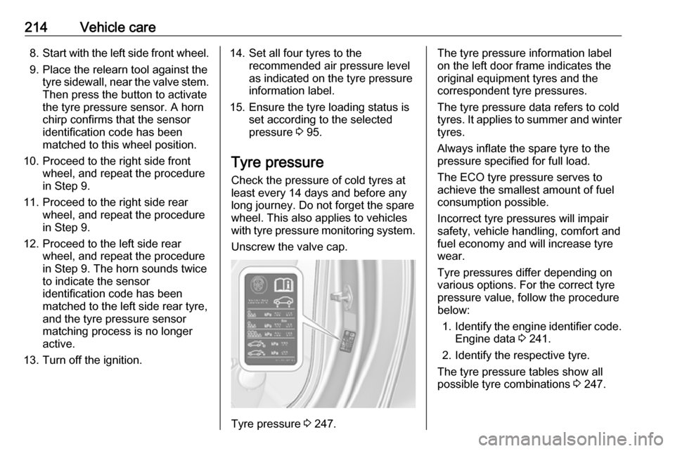
Unscrew the valve cap.
Tyre pressure 3 247.
The tyre pressure information label
on the left door frame indicates the
original equipment tyres and the
correspondent tyre pressures.
The tyre pressure data refers to cold
tyres. It applies to summer and winter tyres.
Always inflate the spare tyre to the
pressure specified for full load.
The ECO tyre pressure serves to
achieve the smallest amount of fuel
consumption possible.
Incorrect tyre pressures will impair
safety, vehicle handling, comfort and
fuel economy and will increase tyre
wear.
Tyre pressures differ depending on
various options. For the correct tyre
pressure value, follow the procedure
below:
1. Identify the engine identifier code.
Engine data 3 241.
2. Identify the respective tyre.
The tyre pressure tables show all
possible tyre combinations 3 247.
Page 220 of 263

218Vehicle care
4.Screw the compressor air hose to
the connection on the sealant
bottle.
5. Fit the sealant bottle into the retainer on the compressor.
Set the compressor near the tyre
in such a way that the sealant
bottle is upright.6. Unscrew valve cap from defective
tyre.
7. Screw the filler hose to the tyre valve.
8. The switch on the compressor must be set to J.
9. Connect the compressor plug to the power outlet or cigarette
lighter socket.
To avoid discharging the vehicle
battery, we recommend running
the engine.10. Set the rocker switch on the compressor to I. The tyre is filled
with sealant.
11. The compressor pressure gauge briefly indicates up to 6 bar whilstthe sealant bottle is emptying
(approx. 30 seconds). Then the
pressure starts to drop.
12. All of the sealant is pumped into the tyre. Then the tyre is inflated.
13. The prescribed tyre pressure should be obtained within
10 minutes. Tyre pressure
3 247 . When the correct pressure
is obtained, switch off the
compressor.
Page 228 of 263

226Vehicle careJump startingDo not start with quick charger.
A vehicle with a discharged vehicle
battery can be started using jump
leads and the vehicle battery of
another vehicle.9 Warning
Be extremely careful when starting
with jump leads. Any deviation
from the following instructions can
lead to injuries or damage caused
by battery explosion or damage to the electrical systems of both
vehicles.
9 Warning
Avoid contact of the battery with
eyes, skin, fabrics and painted
surfaces. The fluid contains
sulphuric acid which can cause
injuries and damage in the event
of direct contact.
● Never expose the battery to naked flames or sparks.
● A discharged vehicle battery canalready freeze at a temperature
of 0 °C. Defrost the frozen battery
before connecting jump leads.
● Wear eye protection and protective clothing when
handling a battery.
● Use a booster battery with the same voltage (12 Volts). Its
capacity (Ah) must not be much less than that of the discharged
battery.
● Use jump leads with insulated terminals and a cross section of
at least 16 mm 2
(25 mm 2
for
diesel engines).
● Do not disconnect the discharged
battery from the vehicle.
● Switch off all unnecessary electrical consumers.
● Do not lean over the battery during jump starting.
● Do not allow the terminals of one
lead to touch those of the other
lead.
● The vehicles must not come into contact with each other during
the jump starting process.● Apply the parking brake, transmission in neutral,
automatic transmission in P.
● Open the positive terminal protection caps of both batteries.
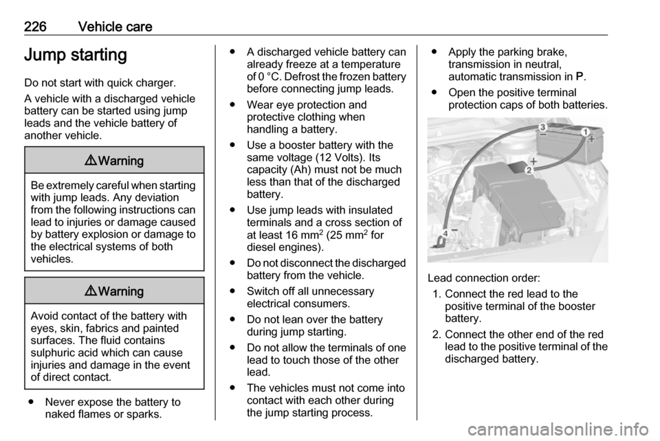
Lead connection order:
1. Connect the red lead to the positive terminal of the booster
battery.
2. Connect the other end of the red lead to the positive terminal of the
discharged battery.
Page 229 of 263

Vehicle care2273. Connect the black lead to thenegative terminal of the booster
battery.
4. Connect the other end of the black
lead to a vehicle grounding point,
such as the engine block or an
engine mounting bolt. Connect as far away from the discharged
battery as possible, however at
least 60 cm.
Route the leads so that they cannot
catch on rotating parts in the engine
compartment.
To start the engine: 1. Start the engine of the vehicle providing the jump.
2. After 5 minutes, start the other engine. Start attempts should be
made for no longer than
15 seconds at an interval of
1 minute.
3. Allow both engines to idle for approx. 3 minutes with the leads
connected.4. Switch on electrical consumers (e.g. headlights, heated rear
window) of the vehicle receiving
the jump start.
5. Reverse above sequence exactly when removing leads.Towing
Towing the vehicle
Insert a screwdriver in the slot at the
lower part of the cap. Release the cap
by carefully moving the screwdriver
downwards.
The towing eye is stowed with the
vehicle tools 3 209.
Page 230 of 263

228Vehicle care
Screw in the towing eye anticlockwise
as far as it will go until it stops in a
horizontal position.
Attach a tow rope – or better still a tow
rod – to the towing eye.
The towing eye must only be used for
towing and not for recovering the
vehicle.
Switch on ignition to release steering
wheel lock and to permit operation of
brake lights, horn and windscreen
wiper.
Transmission in neutral.
Caution
Drive slowly. Do not drive jerkily.
Excessive tractive force can
damage the vehicle.
When the engine is not running,
considerably more force is needed to
brake and steer.
To prevent the entry of exhaust gases from the towing vehicle, switch on the
air recirculation and close the
windows, when soft top is closed.
Vehicles with automatic transmission: The vehicle must be towed facing
forwards, not faster than 50 mph nor further than 60 miles. In all other
cases and when the transmission is
defective, the front axle must be
raised off the ground.
Seek the assistance of a workshop. After towing, unscrew the towing eye
clockwise.
Insert cap at the top and engage
downwards.
Towing another vehicle
Insert a screwdriver in the slot at the
lower bend of the cap. Release the
cap by carefully moving the
screwdriver downwards.
The towing eye is stowed with the
vehicle tools 3 209.
Page 231 of 263

Vehicle care229
Screw in the towing eye anticlockwise
as far as it will go until it stops in a
horizontal position.
The lashing eye at the rear
underneath the vehicle must never be used as a towing eye.
Attach a tow rope – or even better a
tow bar – to the towing eye.
The towing eye must only be used for
towing and not for recovering a
vehicle.
Caution
Drive slowly. Do not drive jerkily.
Excessive tractive force can
damage the vehicle.
After towing, unscrew the towing eye clockwise.
Insert cap at the top and engage
downwards.
Appearance care
Exterior care Locks
The locks are lubricated at the factory using a high quality lock cylinder
grease. Use de-icing agent only when absolutely necessary, as this has a
degreasing effect and impairs lock
function. After using a de-icing agent,
have the locks regreased by a
workshop.
WashingThe paintwork of your vehicle is
exposed to environmental influences,
therefore wash your vehicle regularly.
When using automatic vehicle
washes, we recommend one with
textile brushes and a programme
without wax additives.
When doing a hand wash, use clear
water and a soft brush, cleaning in the
grain direction of the textile hood.
Never use a steam-jet or high-
pressure jet cleaner for the soft top or
the engine compartment.
Page 236 of 263

234Service and maintenanceConfirmations
Confirmation of service is recorded in the Service and Warranty Booklet.The date and mileage is completed
with the stamp and signature of the servicing workshop.
Make sure that the Service and
warranty booklet is completed
correctly as continuous proof of
service is essential if any warranty or goodwill claims are to be met, and is
also a benefit when selling the
vehicle.
Service interval with remaining
engine oil life duration
The service interval is based on
several parameters depending on
usage.
The service display lets you know
when to change the engine oil.
Service display 3 85.Recommended fluids,
lubricants and parts
Recommended fluids andlubricants
Only use products that meet the
recommended specifications.9 Warning
Operating materials are
hazardous and could be
poisonous. Handle with care. Pay
attention to information given on
the containers.
Engine oil
Engine oil is identified by its quality
and its viscosity. Quality is more
important than viscosity when
selecting which engine oil to use. The oil quality ensures e.g. engine
cleanliness, wear protection and oil
aging control, whereas viscosity
grade gives information on the oil's
thickness over a temperature range.
Dexos is the newest engine oil quality
that provides optimum protection for
petrol and diesel engines. If it is
unavailable, engine oils of other listed qualities must be used.
Select the appropriate engine oil
based on its quality and on the
minimum ambient temperature
3 238.
Topping up engine oil
Engine oils of different manufacturers
and brands can be mixed as long as
they comply with the required engine
oil quality and viscosity.
Use of engine oil with only
ACEA A1/B1 or only A5/B5 quality is
prohibited, since it can cause long-
term engine damage under certain
operating conditions.
Select the appropriate engine oil
based on its quality and on the
minimum ambient temperature
3 238.
Additional engine oil additives
The use of additional engine oil
additives could cause damage and
invalidate the warranty.
Page 237 of 263

Service and maintenance235Engine oil viscosity grades
The SAE viscosity grade gives
information on the thickness of the oil.
Multigrade oil is indicated by two
figures, e.g. SAE 5W-30. The first
figure, followed by a W, indicates the
low temperature viscosity and the
second figure the high temperature
viscosity.
Select the appropriate viscosity grade depending on the minimum ambient
temperature 3 238.
All of the recommended viscosity
grades are suitable for high ambient
temperatures.
Coolant and antifreeze
Use only organic acid type-long life
coolant (LLC) antifreeze approved for
the vehicle. Consult a workshop.
The system is factory filled with
coolant designed for excellent
corrosion protection and frost
protection down to approx. -28 °C. In
northern countries with very low
temperatures the factory filled coolant
provides frost protection down to
approx. -37 °C. This concentrationshould be maintained all year round.
The use of additional coolant
additives that intend to give additional
corrosion protection or seal against
minor leaks can cause function
problems. Liability for consequences resulting from the use of additional
coolant additives will be rejected.
Brake and clutch fluidOver time, brake fluid absorbs
moisture which will reduce braking
effectiveness. The brake fluid should
therefore be replaced at the specified interval.
AdBlue
Only use AdBlue to reduce the
nitrogen oxides in the exhaust
emission 3 143.
Page 238 of 263

236Technical dataTechnical dataVehicle identification..................236
Vehicle Identification Number ..236
Identification plate ...................236
Engine identification ................237
Vehicle data ............................... 238
Recommended fluids and lubricants ................................ 238
Engine data ............................. 241
Performance ............................ 242
Vehicle weight ......................... 244
Vehicle dimensions .................244
Capacities ................................ 246
Tyre pressures ........................ 247Vehicle identification
Vehicle IdentificationNumber
The Vehicle Identification Number
may be stamped on the identification plate and on the floor pan, under thefloor covering, visible under a cover.
The Vehicle Identification Number
may be embossed on the instrument
panel, visible through the windscreen,
or in the engine compartment on the
right body panel.
Identification plate
The identification plate is located on
the front left or right door frame.
Page 239 of 263

Technical data237Information on identification label:1:Manufacturer2:Type approval number3:Vehicle Identification Number4:Permissible gross vehicle weight
rating in kg5:Permissible gross train weight
in kg6:Maximum permissible front axle
load in kg7:Maximum permissible rear axle
load in kg8:Vehicle-specific or country-
specific data
The combined total of front and rear
axle loads must not exceed the
permissible gross vehicle weight. For
example, if the front axle is bearing its
maximum permissible load, the rear
axle can only bear a load that is equal
to the gross vehicle weight minus the front axle load.
The technical data is determined in
accordance with European
Community standards. We reserve
the right to make modifications.
Specifications in the vehicle
documents always have priority over
those given in this manual.
Engine identification
The technical data tables show the
engine identifier code. Engine data
3 241.
To identify the respective engine,
refer to the engine power in the EEC
Certificate of Conformity provided
with your vehicle or other national
registration documents.