engine VAUXHALL COMBO 2014 Owner's Manual
[x] Cancel search | Manufacturer: VAUXHALL, Model Year: 2014, Model line: COMBO, Model: VAUXHALL COMBO 2014Pages: 187, PDF Size: 4.15 MB
Page 5 of 187

Introduction3Vehicle specific data
Please enter your vehicle's data on
the previous page to keep it easily
accessible. This information is
available in the sections "Service and maintenance" and "Technical data"
as well as on the identification plate.
Introduction
Your vehicle is a designed
combination of advanced technology, safety, environmental friendliness
and economy.
This Owner's Manual provides you
with all the necessary information to
enable you to drive your vehicle
safely and efficiently.
Make sure your passengers are
aware of the possible risk of accident
and injury which may result from
improper use of the vehicle.
You must always comply with the
specific laws and regulations of the
country that you are in. These laws
may differ from the information in this Owner's Manual.When this Owner's Manual refers to aworkshop visit, we recommend your
Vauxhall Authorised Repairer.
All Vauxhall Authorised Repairers
provide first-class service at
reasonable prices. Experienced
mechanics trained by Vauxhall work
according to specific Vauxhall
instructions.
The customer literature pack should
always be kept ready to hand in the
vehicle.
Using this manual ■ This manual describes all options and features available for this
model. Certain descriptions,
including those for display and
menu functions, may not apply to
your vehicle due to model variant,
country specifications, special
equipment or accessories.
■ The "In brief" section will give you an initial overview.
■ The table of contents at the beginning of this manual and withineach section shows where the
information is located.■ The index will enable you to search
for specific information.
■ This Owner's Manual depicts left- hand drive vehicles. Operation is
similar for right-hand drive vehicles.
■ The Owner's Manual uses the factory engine designations. The
corresponding sales designations
can be found in the section
"Technical data".
■ Directional data, e.g. left or right, or
front or back, always relate to the
direction of travel.
■ The vehicle display screens may not support your specific language.
■ Display messages and interior labelling are written in bold letters.
Danger, Warnings and
Cautions9 Danger
Text marked 9 Danger provides
information on risk of fatal injury.
Disregarding this information may
endanger life.
Page 18 of 187
16In brief
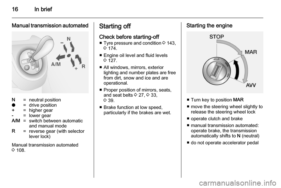
Manual transmission automatedN=neutral positiono=drive position+=higher gear-=lower gearA/M=switch between automatic
and manual modeR=reverse gear (with selector
lever lock)
Manual transmission automated
3 108.
Starting off
Check before starting-off ■ Tyre pressure and condition 3 143,
3 174.
■ Engine oil level and fluid levels 3 127.
■ All windows, mirrors, exterior lighting and number plates are free
from dirt, snow and ice and are
operational.
■ Proper position of mirrors, seats, and seat belts 3 27, 3 33,
3 39.
■ Brake function at low speed, particularly if the brakes are wet.Starting the engine
■ Turn key to position MAR
■ move the steering wheel slightly to release the steering wheel lock
■ operate clutch and brake
■ manual transmission automated: operate brake, the transmission
automatically shifts to N (neutral)
■ do not operate accelerator pedal
Page 19 of 187
In brief17
■ diesel engines: turn the key toposition MAR for preheating and
wait until control indicator ! goes
out
■ turn key to position AVV and
release
Starting the engine 3 102.Stop-start system
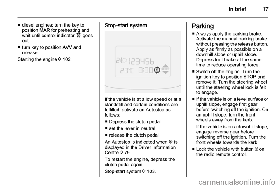
If the vehicle is at a low speed or at a
standstill and certain conditions are
fulfilled, activate an Autostop as
follows:
■ Depress the clutch pedal
■ set the lever in neutral
■ release the clutch pedal
An Autostop is indicated when ^ is
displayed in the Driver Information
Centre 3 79.
To restart the engine, depress the
clutch pedal again.
Stop-start system 3 103.
Parking
■ Always apply the parking brake. Activate the manual parking brake
without pressing the release button.
Apply as firmly as possible on a
downhill slope or uphill slope.
Depress foot brake at the same
time to reduce operating force.
■ Switch off the engine. Turn the ignition key to position STOP and
remove it. Turn the steering wheel
until the steering wheel lock is felt
to engage.
■ If the vehicle is on a level surface or
uphill slope, engage first gear
before switching off the ignition. On
an uphill slope, turn the front
wheels away from the kerb.
If the vehicle is on a downhill slope, engage reverse gear before
switching off the ignition. Turn the
front wheels towards the kerb.
■ Lock the vehicle with button e on
the radio remote control.
Page 20 of 187

18In brief
■Do not park the vehicle on an easily
ignitable surface. The high
temperature of the exhaust system
could ignite the surface.
■ Close the windows.
■ The engine cooling fans may run after the engine has been switchedoff 3 126.
■ After running at high engine speeds
or with high engine loads, operate
the engine briefly at a low load or
run in neutral for
approx. 30 seconds before
switching off, in order to protect the
turbocharger.
Keys, locks 3 19, Laying the vehicle
up for a long period of time 3 125.
Page 29 of 187

Keys, doors and windows27
If the control indicator d illuminates
when starting, there is a fault in the system; the engine cannot be started. Switch off the ignition and repeat the
start attempt.
If d remains illuminated, attempt to
start the engine using the spare key
and seek the assistance of a
workshop.
Notice
The immobiliser does not lock the
doors. Always lock the vehicle after
leaving it 3 21.
Control indicator d 3 78.Exterior mirrors
Convex shape
The convex exterior mirror contains
an aspherical area and reduces blind spots. The shape of the mirror makes objects appear smaller, which will
affect the ability to estimate
distances.
Manual adjustment
Adjust mirrors by swivelling lever in
required direction.
The lower mirrors are not adjustable.
Electric adjustment
Select the relevant exterior mirror by
turning the control to left _ or right 6.
Then swivel the control to adjust the
mirror.
In position o no mirror is selected.
Page 30 of 187
28Keys, doors and windowsFolding
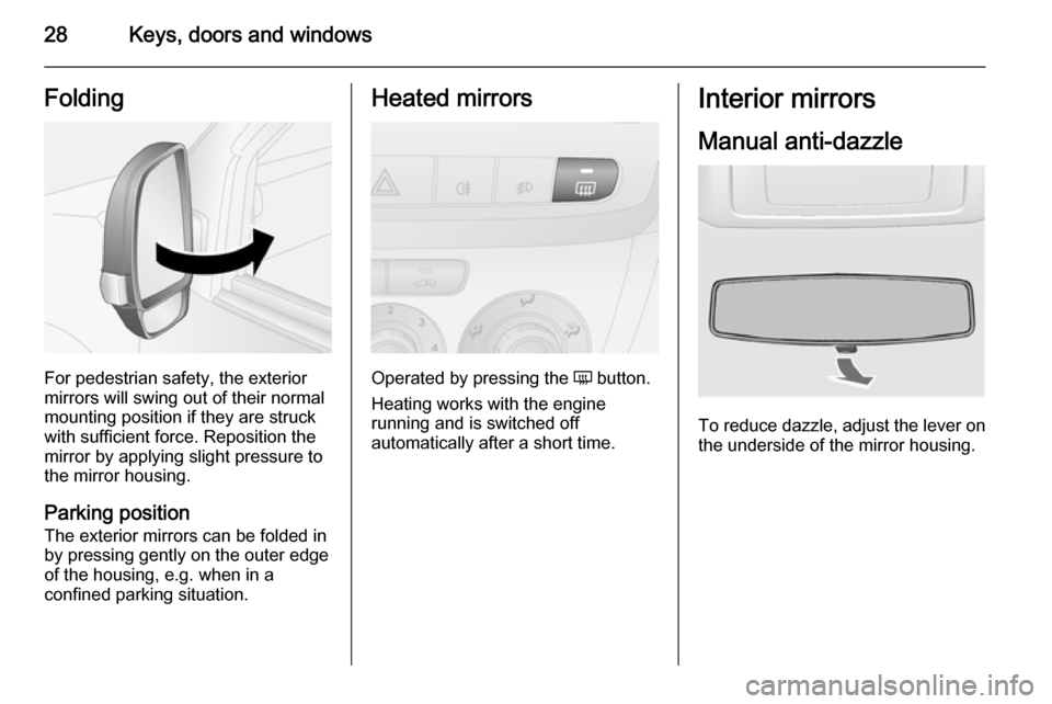
For pedestrian safety, the exterior
mirrors will swing out of their normal
mounting position if they are struck
with sufficient force. Reposition the mirror by applying slight pressure tothe mirror housing.
Parking position
The exterior mirrors can be folded in
by pressing gently on the outer edge
of the housing, e.g. when in a
confined parking situation.
Heated mirrors
Operated by pressing the Ü button.
Heating works with the engine
running and is switched off
automatically after a short time.
Interior mirrors
Manual anti-dazzle
To reduce dazzle, adjust the lever on the underside of the mirror housing.
Page 33 of 187
Keys, doors and windows31Rear windows
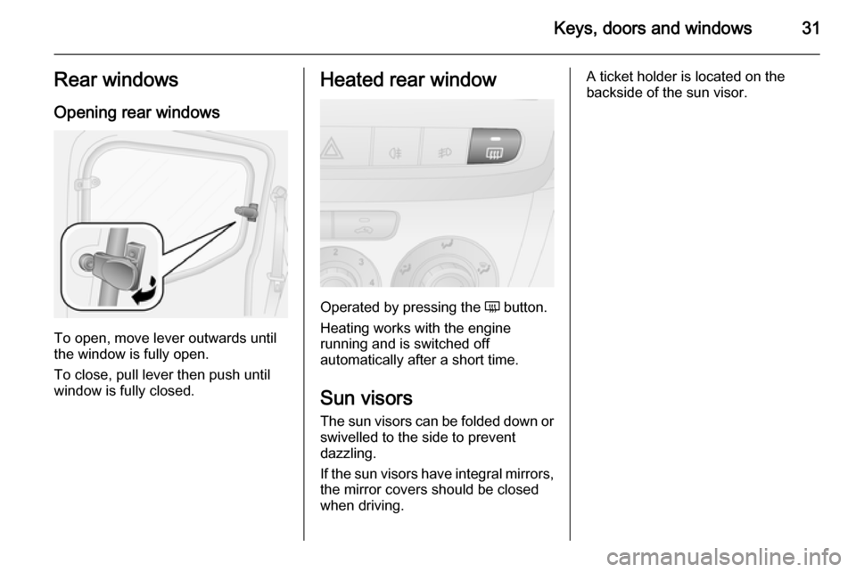
Opening rear windows
To open, move lever outwards until
the window is fully open.
To close, pull lever then push until
window is fully closed.
Heated rear window
Operated by pressing the Ü button.
Heating works with the engine
running and is switched off
automatically after a short time.
Sun visors The sun visors can be folded down orswivelled to the side to prevent
dazzling.
If the sun visors have integral mirrors, the mirror covers should be closed
when driving.
A ticket holder is located on the
backside of the sun visor.
Page 43 of 187

Seats, restraints41Airbag system
The airbag system consists of a
number of individual systems
depending on the scope of
equipment.
When triggered, the airbags inflate
within milliseconds. They also deflate
so quickly that it is often unnoticeable during the collision.
Notice
Depending on the severity of a
collision, the fuel system may also be cut-off and the engine switched
off automatically, for safety reasons.
Resetting the fuel cut-off system;
refer to "Fuel system messages"
3 85.
Notice
Expiry dates for replacing the airbag system components may be found
on the label inside the glovebox.
Contact a workshop to have the
airbag system components
replaced.9 Warning
If handled improperly the airbag
systems can be triggered in an
explosive manner.
Notice
The airbag systems and belt
pretensioner control electronics are
located in the centre console area.
Do not put any magnetic objects in
this area.
Do not fix any objects onto the airbag
covers and do not cover them with
other materials.
Each airbag is triggered only once.
Have deployed airbags replaced by
a workshop. Furthermore, it might be necessary to have the steering
wheel, the instrument panel, parts of
the panelling, the door seals,
handles and the seats replaced.
Do not make any modifications to
the airbag system as this will
invalidate the vehicle type approval.
9 Warning
When the airbags inflate, escaping
hot gases may cause burns.
Control indicator v for airbag systems
3 73.
Fault If there is a fault in the airbag and belttensioner system, the control
indicator v illuminates in the
instrument cluster. The system is not
operational.
Have the cause of the fault remedied
by a workshop.
Control indicator v 3 73.
Child restraint systems on front passenger seat with airbag
systems
Warning according to ECE R94.02:
Page 70 of 187
68Instruments and controls
To reset the trip odometer, press andhold the TRIP button for a few
seconds while the relevant trip
odometer is displayed.
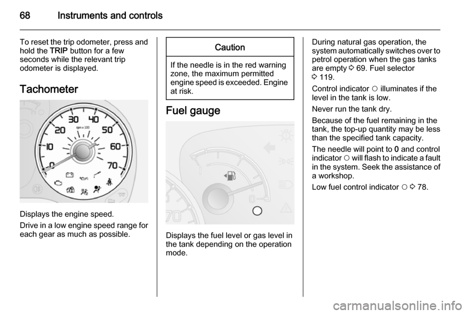
Tachometer
Displays the engine speed.
Drive in a low engine speed range for each gear as much as possible.
Caution
If the needle is in the red warning
zone, the maximum permitted
engine speed is exceeded. Engine at risk.
Fuel gauge
Displays the fuel level or gas level in
the tank depending on the operation
mode.
During natural gas operation, the
system automatically switches over to
petrol operation when the gas tanks
are empty 3 69. Fuel selector
3 119.
Control indicator $ illuminates if the
level in the tank is low.
Never run the tank dry.
Because of the fuel remaining in the
tank, the top-up quantity may be less
than the specified tank capacity.
The needle will point to 0 and control
indicator $ will flash to indicate a fault
in the system. Seek the assistance of a workshop.
Low fuel control indicator $ 3 78.
Page 71 of 187

Instruments and controls69
CNG fuel gauge
In natural gas operation mode, the
four vertical bars next to CNG
correspond to the methane level in
the cylinders. As the fuel level
diminishes, the bars in the CNG fuel
gauge disappear.
CNG and the one remaining bar will
flash if the methane level in the
cylinders is low.
Refuelling 3 120.
Fuel selector
Pressing button Y in the centre
console switches between petrol and
natural gas operation. The LED 1
status shows the current operating
mode.
1 off=natural gas
operation.1 illumi‐
nates=petrol operation.
During natural gas operation, if
control indicator Y illuminates in the
Driver Information Centre (DIC)
3 79, the natural gas tanks are
empty and petrol operation is
automatically engaged.
Fuel for natural gas operation 3 119,
Refuelling 3 120.
Engine coolant
temperature gauge
Displays the coolant temperature.