indicator VAUXHALL COMBO 2014 Owner's Manual
[x] Cancel search | Manufacturer: VAUXHALL, Model Year: 2014, Model line: COMBO, Model: VAUXHALL COMBO 2014Pages: 187, PDF Size: 4.15 MB
Page 19 of 187
In brief17
■ diesel engines: turn the key toposition MAR for preheating and
wait until control indicator ! goes
out
■ turn key to position AVV and
release
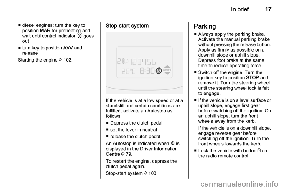
Starting the engine 3 102.Stop-start system
If the vehicle is at a low speed or at a
standstill and certain conditions are
fulfilled, activate an Autostop as
follows:
■ Depress the clutch pedal
■ set the lever in neutral
■ release the clutch pedal
An Autostop is indicated when ^ is
displayed in the Driver Information
Centre 3 79.
To restart the engine, depress the
clutch pedal again.
Stop-start system 3 103.
Parking
■ Always apply the parking brake. Activate the manual parking brake
without pressing the release button.
Apply as firmly as possible on a
downhill slope or uphill slope.
Depress foot brake at the same
time to reduce operating force.
■ Switch off the engine. Turn the ignition key to position STOP and
remove it. Turn the steering wheel
until the steering wheel lock is felt
to engage.
■ If the vehicle is on a level surface or
uphill slope, engage first gear
before switching off the ignition. On
an uphill slope, turn the front
wheels away from the kerb.
If the vehicle is on a downhill slope, engage reverse gear before
switching off the ignition. Turn the
front wheels towards the kerb.
■ Lock the vehicle with button e on
the radio remote control.
Page 29 of 187

Keys, doors and windows27
If the control indicator d illuminates
when starting, there is a fault in the system; the engine cannot be started. Switch off the ignition and repeat the
start attempt.
If d remains illuminated, attempt to
start the engine using the spare key
and seek the assistance of a
workshop.
Notice
The immobiliser does not lock the
doors. Always lock the vehicle after
leaving it 3 21.
Control indicator d 3 78.Exterior mirrors
Convex shape
The convex exterior mirror contains
an aspherical area and reduces blind spots. The shape of the mirror makes objects appear smaller, which will
affect the ability to estimate
distances.
Manual adjustment
Adjust mirrors by swivelling lever in
required direction.
The lower mirrors are not adjustable.
Electric adjustment
Select the relevant exterior mirror by
turning the control to left _ or right 6.
Then swivel the control to adjust the
mirror.
In position o no mirror is selected.
Page 40 of 187

38Seats, restraintsSeat belts
The seat belts are locked during
heavy acceleration or deceleration of
the vehicle holding the occupants in
the sitting position. Therefore the risk
of injury is considerably reduced.
9 Warning
Fasten seat belt before each trip.
In the event of an accident, people
not wearing seat belts endanger their fellow occupants and
themselves.
Seat belts are designed to be used by only one person at a time. Child
restraint system 3 47.
Periodically check all parts of the belt
system for damage, pollution and
proper functionality.
Have damaged components
replaced. After an accident, have the
belts and triggered belt pretensioners replaced by a workshop.
Notice
Make sure that the belts are not
damaged by shoes or sharp-edged
objects or are trapped. Prevent dirt
from getting into the belt retractors.
Seat belt reminder X 3 73.
Belt force limiters On the front seats, stress on the body
is reduced by the gradual release of
the belt during a collision.
Belt pretensioners In the event of a head-on or rear-end
collision of a certain severity, the front
seat belts are tightened.9 Warning
Incorrect handling (e.g. removal or
fitting of belts) can trigger the belt
pretensioners.
Deployment of the belt pretensioners
is indicated by continuous illumination
of control indicator v 3 73.
Triggered belt pretensioners must be replaced by a workshop. Belt
pretensioners can only be triggered
once.
Notice
Do not affix or install accessories or
other objects that may interfere with
the operation of the belt
pretensioners. Do not make any
modifications to belt pretensioner components as this will invalidate
the approval of your vehicle.
Page 43 of 187

Seats, restraints41Airbag system
The airbag system consists of a
number of individual systems
depending on the scope of
equipment.
When triggered, the airbags inflate
within milliseconds. They also deflate
so quickly that it is often unnoticeable during the collision.
Notice
Depending on the severity of a
collision, the fuel system may also be cut-off and the engine switched
off automatically, for safety reasons.
Resetting the fuel cut-off system;
refer to "Fuel system messages"
3 85.
Notice
Expiry dates for replacing the airbag system components may be found
on the label inside the glovebox.
Contact a workshop to have the
airbag system components
replaced.9 Warning
If handled improperly the airbag
systems can be triggered in an
explosive manner.
Notice
The airbag systems and belt
pretensioner control electronics are
located in the centre console area.
Do not put any magnetic objects in
this area.
Do not fix any objects onto the airbag
covers and do not cover them with
other materials.
Each airbag is triggered only once.
Have deployed airbags replaced by
a workshop. Furthermore, it might be necessary to have the steering
wheel, the instrument panel, parts of
the panelling, the door seals,
handles and the seats replaced.
Do not make any modifications to
the airbag system as this will
invalidate the vehicle type approval.
9 Warning
When the airbags inflate, escaping
hot gases may cause burns.
Control indicator v for airbag systems
3 73.
Fault If there is a fault in the airbag and belttensioner system, the control
indicator v illuminates in the
instrument cluster. The system is not
operational.
Have the cause of the fault remedied
by a workshop.
Control indicator v 3 73.
Child restraint systems on front passenger seat with airbag
systems
Warning according to ECE R94.02:
Page 48 of 187
46Seats, restraints
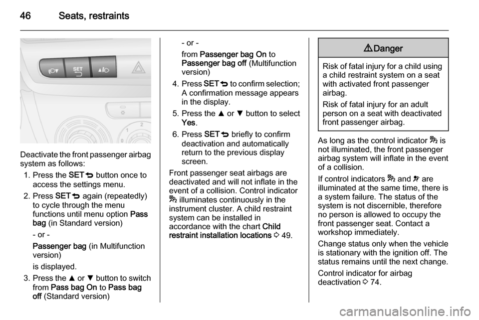
Deactivate the front passenger airbagsystem as follows:
1. Press the SETq button once to
access the settings menu.
2. Press SETq again (repeatedly)
to cycle through the menu
functions until menu option Pass
bag (in Standard version)
- or -
Passenger bag (in Multifunction
version)
is displayed.
3. Press the R or S button to switch
from Pass bag On to Pass bag
off (Standard version)
- or -
from Passenger bag On to
Passenger bag off (Multifunction
version)
4. Press SETq to confirm selection;
A confirmation message appears
in the display.
5. Press the R or S button to select
Yes .
6. Press SETq briefly to confirm
deactivation and automatically
return to the previous display
screen.
Front passenger seat airbags are deactivated and will not inflate in the
event of a collision. Control indicator
* illuminates continuously in the
instrument cluster. A child restraint
system can be installed in
accordance with the chart Child
restraint installation locations 3 49.9 Danger
Risk of fatal injury for a child using
a child restraint system on a seat
with activated front passenger
airbag.
Risk of fatal injury for an adult
person on a seat with deactivated
front passenger airbag.
As long as the control indicator * is
not illuminated, the front passenger
airbag system will inflate in the event
of a collision.
If control indicators * and v are
illuminated at the same time, there is
a system failure. The status of the system is not discernible, therefore
no person is allowed to occupy the
front passenger seat. Contact a
workshop immediately.
Change status only when the vehicle
is stationary with the ignition off. The
status remains until the next change.
Control indicator for airbag
deactivation 3 74.
Page 69 of 187
Instruments and controls67AshtraysCaution
To be used only for ash and not forcombustible rubbish.
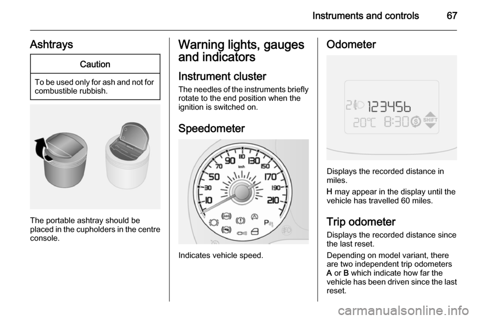
The portable ashtray should be
placed in the cupholders in the centre
console.
Warning lights, gauges
and indicators
Instrument cluster
The needles of the instruments briefly rotate to the end position when the
ignition is switched on.
Speedometer
Indicates vehicle speed.
Odometer
Displays the recorded distance in
miles.
H may appear in the display until the
vehicle has travelled 60 miles.
Trip odometer Displays the recorded distance since
the last reset.
Depending on model variant, there are two independent trip odometers
A or B which indicate how far the
vehicle has been driven since the last
reset.
Page 70 of 187
68Instruments and controls
To reset the trip odometer, press andhold the TRIP button for a few
seconds while the relevant trip
odometer is displayed.
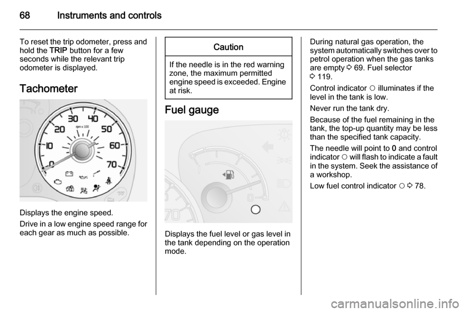
Tachometer
Displays the engine speed.
Drive in a low engine speed range for each gear as much as possible.
Caution
If the needle is in the red warning
zone, the maximum permitted
engine speed is exceeded. Engine at risk.
Fuel gauge
Displays the fuel level or gas level in
the tank depending on the operation
mode.
During natural gas operation, the
system automatically switches over to
petrol operation when the gas tanks
are empty 3 69. Fuel selector
3 119.
Control indicator $ illuminates if the
level in the tank is low.
Never run the tank dry.
Because of the fuel remaining in the
tank, the top-up quantity may be less
than the specified tank capacity.
The needle will point to 0 and control
indicator $ will flash to indicate a fault
in the system. Seek the assistance of a workshop.
Low fuel control indicator $ 3 78.
Page 71 of 187

Instruments and controls69
CNG fuel gauge
In natural gas operation mode, the
four vertical bars next to CNG
correspond to the methane level in
the cylinders. As the fuel level
diminishes, the bars in the CNG fuel
gauge disappear.
CNG and the one remaining bar will
flash if the methane level in the
cylinders is low.
Refuelling 3 120.
Fuel selector
Pressing button Y in the centre
console switches between petrol and
natural gas operation. The LED 1
status shows the current operating
mode.
1 off=natural gas
operation.1 illumi‐
nates=petrol operation.
During natural gas operation, if
control indicator Y illuminates in the
Driver Information Centre (DIC)
3 79, the natural gas tanks are
empty and petrol operation is
automatically engaged.
Fuel for natural gas operation 3 119,
Refuelling 3 120.
Engine coolant
temperature gauge
Displays the coolant temperature.
Page 72 of 187
70Instruments and controls
C=engine operating
temperature not yet
reachedcentral
area=normal operating
temperatureH=temperature too high
If control indicator $ illuminates in
conjunction with a message in the
Driver Information Centre 3 79 the
coolant temperature is too high. Seek
the assistance of a workshop.
Caution
If engine coolant temperature is
too high, stop vehicle, switch off
engine. Danger to engine. Check
coolant level.
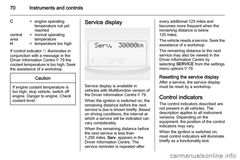
Service display
Service display is available in
vehicles with Multifunction version of the Driver Information Centre 3 79.
When the ignition is switched on, the remaining distance before the next
service is due is shown briefly. Based on driving conditions, the interval at
which a service will be indicated can
vary considerably.
When the remaining distance before
the next service is less than
1,250 miles, Serv. appears in the
Driver Information Centre. The service reminder is repeated after
every additional 125 miles and
becomes more frequent when the
remaining distance is below
125 miles.
The vehicle needs a service. Seek the
assistance of a workshop.
The remaining distance to the next
service may also be viewed in the
Driver Information Centre by
selecting SERVICE from the settings
menu options 3 79.
Resetting the service display After a service, the service displaymust be reset by a workshop.
Control indicators The control indicators described are
not present in all vehicles. The
description applies to all instrument
versions. Depending on the
equipment, the position of the control
indicators may vary.
When the ignition is switched on,
most control indicators will illuminate
briefly as a functionality test.
Page 73 of 187

Instruments and controls71
The control indicator colours mean:red=danger, important
reminderyellow=warning, information, faultgreen=confirmation of activationblue=confirmation of activation