SIDE VAUXHALL COMBO E 2020 Owner's Manual
[x] Cancel search | Manufacturer: VAUXHALL, Model Year: 2020, Model line: COMBO E, Model: VAUXHALL COMBO E 2020Pages: 279, PDF Size: 28.6 MB
Page 224 of 279

222Vehicle careSidelight / daytime running light
with bulbs
1. Rotate the bulb socket anticlockwise to disengage and
withdraw from the reflector.
2. Remove the bulb from the bulb socket by pulling.
3. Replace and insert the new bulb into the bulb socket.
4. Insert the bulb socket into the light
assembly and turn clockwise.
Sidelight / daytime running light
with LEDs
In case of defective LEDs, have them replaced by a workshop.
LED headlights Daytime running lights are designed
as LEDs and can not be changed.
Have lights repaired by a workshop in case of failure.
Front fog lights
1. Wrap a cloth around the tip of a flat
screwdriver to prevent paint
damage. Insert the screwdriver in
the recess at the edge of the
cover. Release the cover by
levering it out carefully.
Page 228 of 279

226Vehicle careTail light / brake light (1)
Turn light / hazard warning flasher ( 2 ) outer bulb
Reversing light ( 3) inner bulb
Rear fog light ( 4)
6. Attach the bulb carrier to the light assembly.
7. Attach the cable to the retainer. 8. Attach the light assembly to the vehicle body and tighten both
screws.
3rd-brake light The 3rd-brake light is designed as
LED and can not be changed.
Have lights repaired by a workshop in case of failure.
Bulb check
Switch on the ignition, operate and
check all lights.Side turn lights
To replace the bulb, remove the lamp
housing:
1. Slide the lamp housing forward and remove it at the back.
2. Press the retaining lug upwardsand remove the bulb socket from
the plug connector.
3. Replace the complete unit.
4. Insert left end of the lamp, slide to
the left and insert right end.
Page 230 of 279
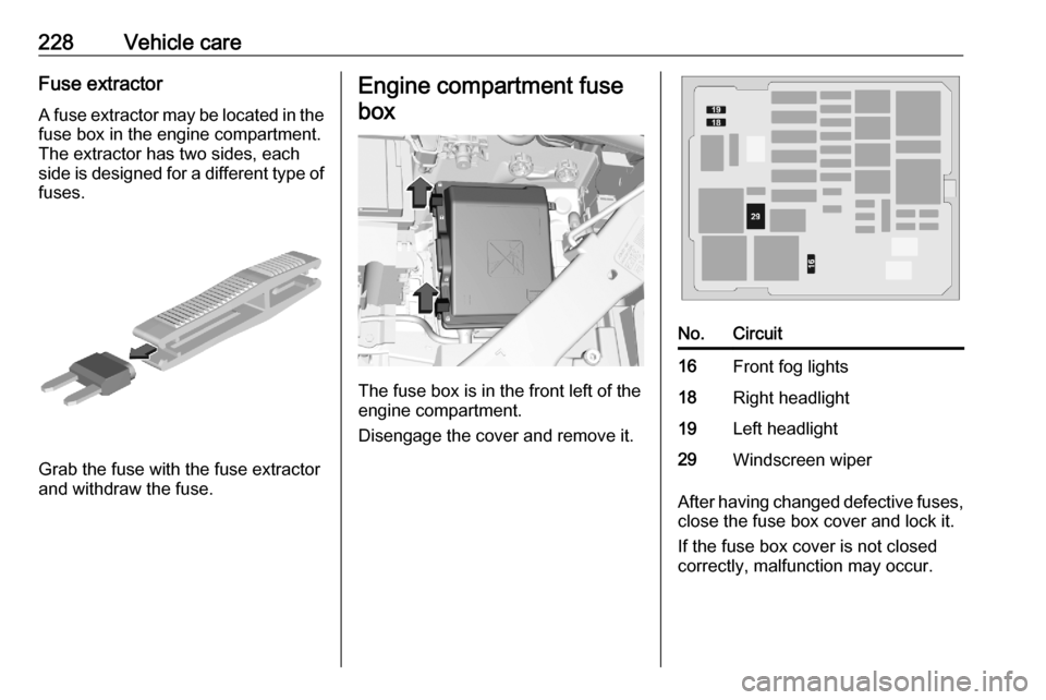
228Vehicle careFuse extractorA fuse extractor may be located in the
fuse box in the engine compartment.
The extractor has two sides, each
side is designed for a different type of fuses.
Grab the fuse with the fuse extractor
and withdraw the fuse.
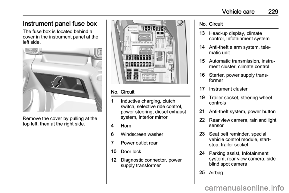
Engine compartment fuse
box
The fuse box is in the front left of the
engine compartment.
Disengage the cover and remove it.
No.Circuit16Front fog lights18Right headlight19Left headlight29Windscreen wiper
After having changed defective fuses,
close the fuse box cover and lock it.
If the fuse box cover is not closed
correctly, malfunction may occur.
Page 231 of 279
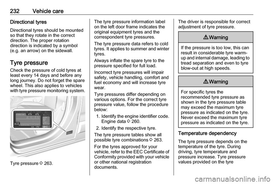
Vehicle care229Instrument panel fuse boxThe fuse box is located behind a
cover in the instrument panel at the
left side.
Remove the cover by pulling at the
top left, then at the right side.
No.Circuit1Inductive charging, clutch
switch, selective ride control,
power steering, diesel exhaust
system, interior mirror4Horn6Windscreen washer7Power outlet rear10Door lock12Diagnostic connector, power
supply transformerNo.Circuit13Head-up display, climate
control, Infotainment system14Anti-theft alarm system, tele‐
matic unit15Automatic transmission, instru‐
ment cluster, climate control16Starter, power supply trans‐
former17Instrument cluster19Trailer socket, steering wheel
controls21Anti-theft system, power button22Rear view camera, rain and light sensor23Seat belt reminder, special
vehicle control module, start-
stop, trailer socket24Parking assist, Infotainment
system, rear view camera, side
blind spot camera25Airbag
Page 234 of 279
232Vehicle careDirectional tyres
Directional tyres should be mounted so that they rotate in the correct
direction. The proper rotation
direction is indicated by a symbol
(e.g. an arrow) on the sidewall.
Tyre pressure
Check the pressure of cold tyres at
least every 14 days and before any
long journey. Do not forget the spare
wheel. This also applies to vehicles
with tyre pressure monitoring system.
Tyre pressure 3 263.
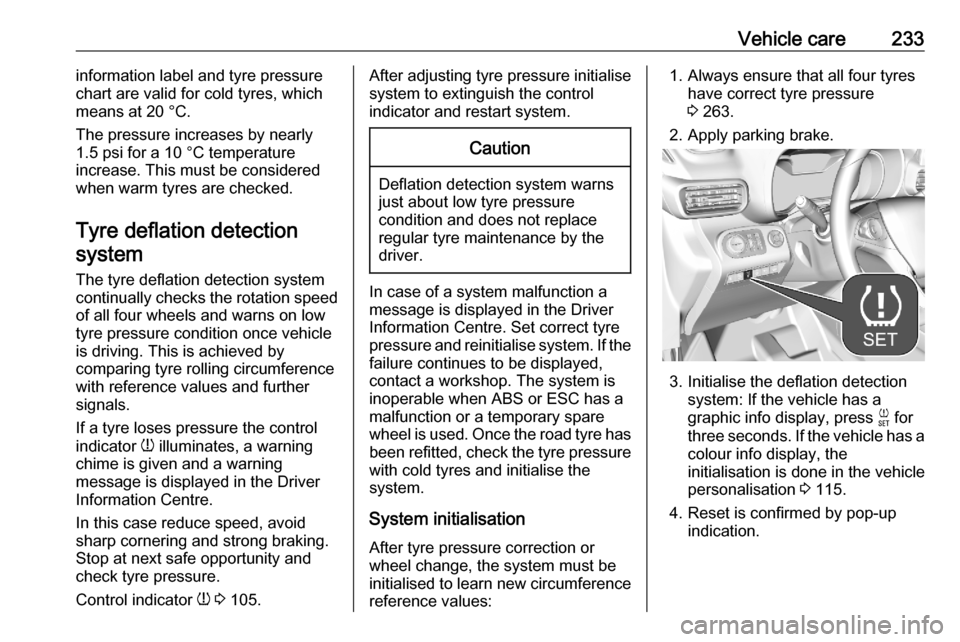
The tyre pressure information label
on the left door frame indicates the
original equipment tyres and the
correspondent tyre pressures.
The tyre pressure data refers to cold
tyres. It applies to summer and winter tyres.
Always inflate the spare tyre to the
pressure specified for full load.
Incorrect tyre pressures will impair
safety, vehicle handling, comfort and
fuel economy and will increase tyre
wear.
Tyre pressures differ depending on
various options. For the correct tyre
pressure value, follow the procedure
below:
1. Identify the engine identifier code.
Engine data 3 260.
2. Identify the respective tyre.
The tyre pressure tables show all
possible tyre combinations 3 263.
For the tyres approved for your
vehicle, refer to the EEC Certificate of Conformity provided with your vehicle
or other national registration
documents.The driver is responsible for correct adjustment of tyre pressure.9 Warning
If the pressure is too low, this can
result in considerable tyre warm-
up and internal damage, leading to tread separation and even to tyre
blow-out at high speeds.
9 Warning
For specific tyres the
recommended tyre pressure as
shown in the tyre pressure table may exceed the maximum tyre
pressure as indicated on the tyre.
Never exceed the maximum tyre
pressure as indicated on the tyre.
Temperature dependency
The tyre pressure depends on the
temperature of the tyre. During
driving, tyre temperature and
pressure increase. Tyre pressure
values provided on the tyre
Page 235 of 279
Vehicle care233information label and tyre pressure
chart are valid for cold tyres, which
means at 20 °C.
The pressure increases by nearly
1.5 psi for a 10 °C temperature
increase. This must be considered
when warm tyres are checked.
Tyre deflation detectionsystem
The tyre deflation detection system
continually checks the rotation speed
of all four wheels and warns on low
tyre pressure condition once vehicle
is driving. This is achieved by
comparing tyre rolling circumference
with reference values and further
signals.
If a tyre loses pressure the control
indicator w illuminates, a warning
chime is given and a warning
message is displayed in the Driver
Information Centre.
In this case reduce speed, avoid
sharp cornering and strong braking.
Stop at next safe opportunity and
check tyre pressure.
Control indicator w 3 105.After adjusting tyre pressure initialise
system to extinguish the control
indicator and restart system.Caution
Deflation detection system warns
just about low tyre pressure
condition and does not replace
regular tyre maintenance by the
driver.
In case of a system malfunction a
message is displayed in the Driver
Information Centre. Set correct tyre
pressure and reinitialise system. If the
failure continues to be displayed,
contact a workshop. The system is
inoperable when ABS or ESC has a
malfunction or a temporary spare
wheel is used. Once the road tyre has
been refitted, check the tyre pressure with cold tyres and initialise the
system.
System initialisation
After tyre pressure correction or
wheel change, the system must be
initialised to learn new circumference reference values:
1. Always ensure that all four tyres have correct tyre pressure
3 263.
2. Apply parking brake.
3. Initialise the deflation detection system: If the vehicle has a
graphic info display, press F for
three seconds. If the vehicle has a
colour info display, the
initialisation is done in the vehicle
personalisation 3 115.
4. Reset is confirmed by pop-up indication.
Page 236 of 279
234Vehicle careAfter initialisation system
automatically calibrates to new tyre
pressures during driving. After longer
drive the system will adopt and
monitor new pressures.
Always check tyre pressure with cold
tyres.
System has to be reinitialised when: ● Tyre pressure has been changed
● Load condition has been changed
● Wheels have been swapped or exchanged
The system will not warn
instantaneously on a tyre blow out or a rapid deflation. This is due to
required calculation time.
Tread depth
Check tread depth at regular
intervals.
Tyres should be replaced for safety
reasons at a tread depth of 2-3 mm
(4 mm for winter tyres).For safety reasons, it is
recommended that the tread depth of
the tyres on one axle should not vary
by more than 2 mm.
The legally permissible minimum
tread depth (1.6 mm) has been
reached when the tread has worn
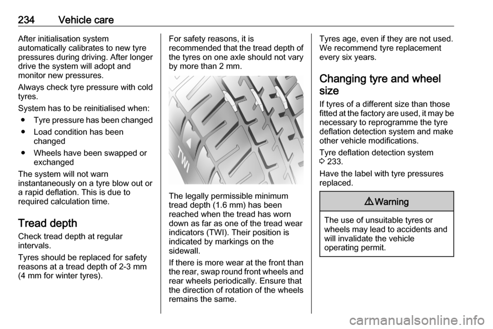
down as far as one of the tread wear
indicators (TWI). Their position is
indicated by markings on the
sidewall.
If there is more wear at the front than
the rear, swap round front wheels and rear wheels periodically. Ensure that
the direction of rotation of the wheels
remains the same.
Tyres age, even if they are not used.
We recommend tyre replacement
every six years.
Changing tyre and wheel size
If tyres of a different size than those
fitted at the factory are used, it may be necessary to reprogramme the tyre
deflation detection system and make
other vehicle modifications.
Tyre deflation detection system
3 233.
Have the label with tyre pressures
replaced.9 Warning
The use of unsuitable tyres or
wheels may lead to accidents and will invalidate the vehicle
operating permit.
Page 237 of 279
Vehicle care235Wheel covers
Wheel covers and tyres that are
factory approved for the respective
vehicle and comply with all of the
relevant wheel and tyre combination
requirements must be used.
If the wheel covers and tyres used are
not factory approved, the tyres must
not have a rim protection ridge.
Wheel covers must not impair brake
cooling.9 Warning
Use of unsuitable tyres or wheel
covers could lead to sudden
pressure loss and thereby
accidents.
Vehicles with steel wheels: When
using locking wheel nuts, do not
attach wheel covers.
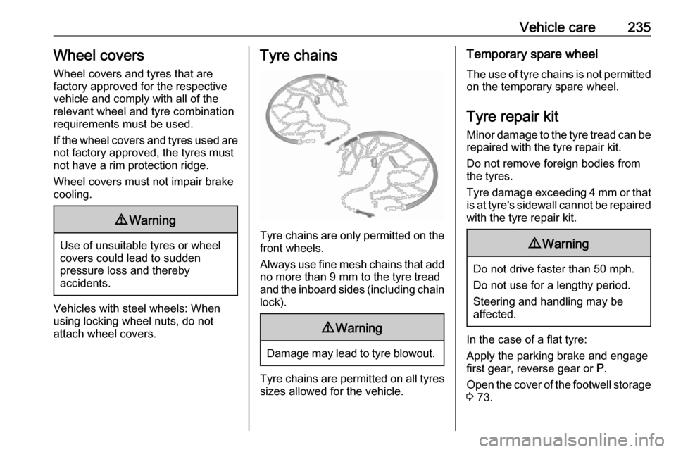
Tyre chains
Tyre chains are only permitted on the
front wheels.
Always use fine mesh chains that add no more than 9 mm to the tyre tread
and the inboard sides (including chain
lock).
9 Warning
Damage may lead to tyre blowout.
Tyre chains are permitted on all tyres
sizes allowed for the vehicle.
Temporary spare wheel
The use of tyre chains is not permitted on the temporary spare wheel.
Tyre repair kit
Minor damage to the tyre tread can be
repaired with the tyre repair kit.
Do not remove foreign bodies from
the tyres.
Tyre damage exceeding 4 mm or that
is at tyre's sidewall cannot be repaired with the tyre repair kit.9 Warning
Do not drive faster than 50 mph.
Do not use for a lengthy period.
Steering and handling may be
affected.
In the case of a flat tyre:
Apply the parking brake and engage
first gear, reverse gear or P.
Open the cover of the footwell storage
3 73.
Page 238 of 279

236Vehicle care
The tyre repair kit is located in the
storage compartment underneath the passenger front seat.
1. Remove the sealant bottle and the
compressor.
2. Pull speed limit label from sealant
bottle and place it in driver's
visible area.3. Remove the electrical connection cable and air hose from the
storage compartments on the
underside of the compressor.
4. Screw the compressor air hose to
the connection on the sealant
bottle.
5. Fit the sealant bottle into the bracket on the compressor.
Set the compressor near the tyre
in such a way that the sealant
bottle is upright.
6. Unscrew valve cap from defective
tyre.
7. Screw the filler hose to the tyre valve.
8. The switch on the compressor must be set to J.
Page 243 of 279
Vehicle care2415. Change the wheel.
6. Position the damaged wheel with the outside down in the spare
wheel holder.
7. Lift the spare wheel holder and engage in the catch. The open
side of the catch must point in the direction of travel.
8. Close the spare wheel holder by turning the hexagon bolt
clockwise using the wheel
wrench.
9. Stow wheel wrench in the storage.
10. Close the tailgate or the rear doors.
Only mount one temporary spare
wheel. The permissible maximum
speed on the label on the temporary
spare wheel is only valid for the
factory-fitted tyre size.
Fitting the spare wheel Make the following preparations and
observe the following information:
● Park the vehicle on a level, firm and non-skid surface. The front
wheels must be in the straight-
ahead position.● If necessary, place a chock under
the wheel diagonally opposite the wheel to be changed.
● Apply the parking brake and engage first gear, reverse gear or
P .
● Remove the spare wheel 3 240.
● Never change more than one wheel at once.
● Use the jack only to change wheels in case of puncture, not
for seasonal winter or summer
tyre change.
● The jack is maintenance-free. ● If the ground on which the vehicle
is standing is soft, a solid board
(max. 1 cm thick) should be
placed under the jack.
● Take heavy objects out of the vehicle before jacking up.
● No people or animals may be in the vehicle when it is jacked-up.
● Never crawl under a jacked-up vehicle.
● Do not start the vehicle when it is
raised on the jack.● Before screwing in the wheel bolts, clean them.9Warning
Do not grease wheel bolts.
9Warning
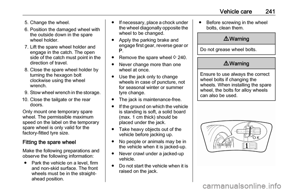
Ensure to use always the correct
wheel bolts if changing the
wheels. When installing the spare
wheel, the bolts for alloy wheels can also be used.