brake light VAUXHALL COMBO E 2020 Owner's Guide
[x] Cancel search | Manufacturer: VAUXHALL, Model Year: 2020, Model line: COMBO E, Model: VAUXHALL COMBO E 2020Pages: 279, PDF Size: 28.6 MB
Page 201 of 279

Driving and operating199● the change of trajectory is notaccompanied by operation of theturn signals
● the Electronic Stability Control is activated and not in operation
● the vehicle is not connected to a trailer or an electric bicycle carrier
● normal driving behaviour (system
detects dynamic driving style, i.e. pressure on the brake or
accelerator pedal)
● roads with poor lane markings
● no spare wheel is used
● the driver needs to be active during the correction
● the vehicle is not driven in a tight
cornerActivation
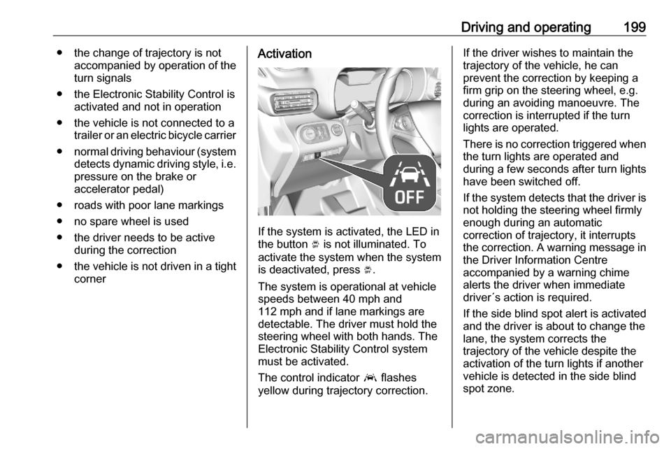
If the system is activated, the LED in
the button Ó is not illuminated. To
activate the system when the system
is deactivated, press Ó.
The system is operational at vehicle
speeds between 40 mph and
112 mph and if lane markings are
detectable. The driver must hold the
steering wheel with both hands. The Electronic Stability Control system
must be activated.
The control indicator a flashes
yellow during trajectory correction.
If the driver wishes to maintain the
trajectory of the vehicle, he can
prevent the correction by keeping a
firm grip on the steering wheel, e.g.
during an avoiding manoeuvre. The correction is interrupted if the turn
lights are operated.
There is no correction triggered when
the turn lights are operated and
during a few seconds after turn lights
have been switched off.
If the system detects that the driver is not holding the steering wheel firmly
enough during an automatic
correction of trajectory, it interrupts
the correction. A warning message in
the Driver Information Centre
accompanied by a warning chime
alerts the driver when immediate
driver´s action is required.
If the side blind spot alert is activated
and the driver is about to change the
lane, the system corrects the
trajectory of the vehicle despite the
activation of the turn lights if another
vehicle is detected in the side blind
spot zone.
Page 208 of 279

206Driving and operatingTrailer hitch
General information
Only use towing equipment that has
been approved for your vehicle.
Entrust retrofitting of towing
equipment to a workshop. It may be
necessary to make changes that
affect the cooling system, heat
shields or other equipment.
The bulb outage detection function for trailer brake light cannot detect a
partial bulb outage e.g. in case of four
bulbs with a power of 5 W each, the
function only detects lamp outage
when only a single 5 W lamp remains
or none remain.
Fitting of towing equipment could
cover the opening of the towing eye.
If this is the case use the coupling ball bar for towing. Always keep the
coupling ball bar in the vehicle to have
it on hand if needed.Driving characteristics and
towing tips
Before attaching a trailer, lubricate
the coupling ball. However, do not do
so if a stabiliser, which acts on the coupling ball, is being used to reduce snaking movements.
During trailer towing do not exceed a
speed of 50 mph. A maximum speed
of 60 mph is only appropriate if an
oscillation damper is used and the
permissible gross trailer weight does
not exceed the vehicle's curb weight.
For trailers with low driving stability
and caravan trailers, the use of an
oscillation damper is strongly
recommended.
If the trailer starts snaking, drive more slowly, do not attempt to correct the
steering and brake sharply if
necessary.
When driving downhill, drive in the
same gear as if driving uphill and
drive at a similar speed.
Adjust tyre pressure to the value
specified for full load 3 263.Trailer towing
Trailer loadsThe permissible trailer loads are
vehicle and engine-dependent
maximum values which must not be exceeded. The actual trailer load is
the difference between the actual
gross weight of the trailer and the
actual coupling socket load with the trailer coupled.
The permissible trailer loads are
specified in the vehicle documents. In general, they are valid for inclines up
to 12%.
The permissible trailer load applies
up to the specified incline and at sea
level. Since engine power decreases
as altitude increases due to the air
becoming thinner, therefore reducing
climbing ability, the permissible gross
train weight also decreases by 10%
for every 1000 metres of altitude. The gross train weight does not have to be
reduced when driving on roads with
slight inclines (less than 8%, e.g.
motorways).
Page 213 of 279

Vehicle care211Vehicle careGeneral Information...................211
Accessories and vehicle modifications .......................... 211
Vehicle storage ........................212
End-of-life vehicle recovery .....213
Vehicle checks ........................... 213
Performing work ......................213
Bonnet ..................................... 213
Engine oil ................................. 214
Engine coolant ......................... 215
Washer fluid ............................ 216
Brakes ..................................... 216
Brake fluid ............................... 216
Vehicle battery ......................... 217
Diesel fuel system bleeding .....219
Wiper blade replacement ........219
Bulb replacement .......................220
Halogen headlights ..................220
LED headlights ........................ 222
Front fog lights ......................... 222
Front turn lights .......................223
Tail lights ................................. 224
Side turn lights ......................... 226
Number plate light ...................227
Interior lights ............................ 227Electrical system........................227
Fuses ....................................... 227
Engine compartment fuse box . 228
Instrument panel fuse box .......229
Vehicle tools .............................. 230
Tools ........................................ 230
Wheels and tyres .......................231
Winter tyres ............................. 231
Tyre designations ....................231
Tyre pressure .......................... 232
Tyre deflation detection system .................................... 233
Tread depth ............................. 234
Changing tyre and wheel size . 234
Wheel covers ........................... 235
Tyre chains .............................. 235
Tyre repair kit .......................... 235
Wheel changing .......................238
Spare wheel ............................ 240
Jump starting ............................. 243
Towing ....................................... 245
Towing the vehicle ...................245
Towing another vehicle ...........246
Appearance care .......................247
Exterior care ............................ 247
Interior care ............................. 249
Floor mats ............................... 249General Information
Accessories and vehicle modifications
We recommend the use of genuine parts and accessories and factory
approved parts specific for your
vehicle type. We cannot assess or
guarantee reliability of other products - even if they have a regulatory or
otherwise granted approval.
Any modification, conversion or other
changes made to standard vehicle
specifications (including, without
limitation, software modifications,
modifications of the electronic control units) may invalidate the warranty
offered by Vauxhall. Furthermore,
such changes may affect driver
assistance systems, may impact fuel
consumption, CO 2 emissions and
other emissions of the vehicle and
cause the vehicle to no longer
conform to the operating permit,
impacting the validity of your vehicle
registration.
Page 227 of 279

Vehicle care2255. Push the bulb slightly down, turnit and remove it from the bulb
carrier. Replace the bulb:
Rear fog light ( 1)
Reversing light ( 2)
Turn light / hazard warning flasher ( 3 )
Tail light / brake light ( 4)
6. Attach the bulb carrier to the light assembly.
7. Attach the cable to the retainer.
8. Attach the light assembly to the vehicle body and tighten both
screws.
Vehicle with rear doors1. Unscrew and remove the two screws.
2. Carefully withdraw the tail lightassembly from recess and
remove. Take care that the cable
duct remains in position.
3. Detach the cable from the retainer.
4. Disengage the retaining lugs toremove the bulb carrier.
5. Push the bulb slightly down, turnit and remove it from the bulb
carrier. Replace the bulb:
Page 228 of 279

226Vehicle careTail light / brake light (1)
Turn light / hazard warning flasher ( 2 ) outer bulb
Reversing light ( 3) inner bulb
Rear fog light ( 4)
6. Attach the bulb carrier to the light assembly.
7. Attach the cable to the retainer. 8. Attach the light assembly to the vehicle body and tighten both
screws.
3rd-brake light The 3rd-brake light is designed as
LED and can not be changed.
Have lights repaired by a workshop in case of failure.
Bulb check
Switch on the ignition, operate and
check all lights.Side turn lights
To replace the bulb, remove the lamp
housing:
1. Slide the lamp housing forward and remove it at the back.
2. Press the retaining lug upwardsand remove the bulb socket from
the plug connector.
3. Replace the complete unit.
4. Insert left end of the lamp, slide to
the left and insert right end.
Page 246 of 279

244Vehicle care● A discharged vehicle battery canalready freeze at a temperature
of 0 °C. Defrost the frozen battery before connecting jump leads.
● Wear eye protection and protective clothing when
handling a battery.
● Use a booster battery with the same voltage (12 V). Its capacity
(Ah) must not be much less than
that of the discharged vehicle
battery.
● Use jump leads with insulated terminals and a cross section of
at least 16 mm 2
(25 mm 2
for
diesel engines).
● Do not disconnect the discharged
vehicle battery from the vehicle.
● Switch off all unnecessary electrical consumers.
● Do not lean over the vehicle battery during jump starting.
● Do not allow the terminals of one
lead to touch those of the other
lead.● The vehicles must not come into contact with each other during
the jump starting process.
● Apply the parking brake, transmission in neutral,
automatic transmission in P.
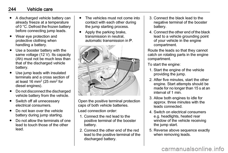
Open the positive terminal protection
caps of both vehicle batteries.
Lead connection order: 1. Connect the red lead to the positive terminal of the booster
battery.
2. Connect the other end of the red lead to the positive terminal of the
discharged battery.
3. Connect the black lead to the negative terminal of the boosterbattery.
4. Connect the other end of the black
lead to a vehicle grounding point
of your vehicle in the engine
compartment.
Route the leads so that they cannot
catch on rotating parts in the engine
compartment.
To start the engine: 1. Start the engine of the vehicle providing the jump.
2. After five minutes, start the other engine. Start attempts should be
made for no longer than 15 s at an interval of 1 min.
3. Allow both engines to idle for approx. three minutes with the
leads connected.
4. Switch on electrical consumers e.g. headlights, heated rear
window of the vehicle receiving
the jump start.
5. Reverse above sequence exactly when removing leads.
Page 247 of 279

Vehicle care245Towing
Towing the vehicle
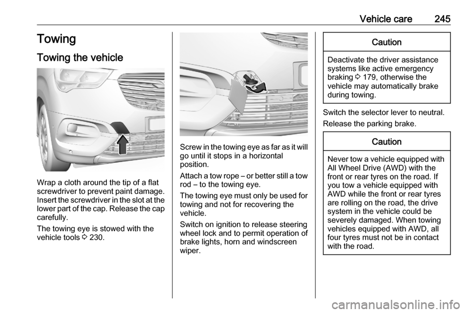
Wrap a cloth around the tip of a flat
screwdriver to prevent paint damage. Insert the screwdriver in the slot at the
lower part of the cap. Release the cap carefully.
The towing eye is stowed with the
vehicle tools 3 230.
Screw in the towing eye as far as it will
go until it stops in a horizontal
position.
Attach a tow rope – or better still a tow
rod – to the towing eye.
The towing eye must only be used for
towing and not for recovering the
vehicle.
Switch on ignition to release steering wheel lock and to permit operation of
brake lights, horn and windscreen
wiper.
Caution
Deactivate the driver assistance
systems like active emergency
braking 3 179, otherwise the
vehicle may automatically brake during towing.
Switch the selector lever to neutral.
Release the parking brake.
Caution
Never tow a vehicle equipped with All Wheel Drive (AWD) with the
front or rear tyres on the road. If
you tow a vehicle equipped with
AWD while the front or rear tyres
are rolling on the road, the drive
system in the vehicle could be
severely damaged. When towing
vehicles equipped with AWD, all
four tyres must not be in contact
with the road.
Page 251 of 279

Vehicle care249Liquid gas system9Danger
Liquid gas is heavier than air and
can collect in sink points.
Take care when performing work
at the underbody in a pit.
For painting work and when using a
drying booth at a temperature above
60 °C, the liquid gas tank must be
removed.
Do not make any modifications to the
liquid gas system.
Towing equipment
Do not clean the coupling ball bar with a steam-jet or high-pressure jet
cleaner.
Interior care
Interior and upholstery
Only clean the vehicle interior,
including the instrument panel fascia
and panelling, with a dry cloth or
interior cleaner.
Clean the leather upholstery with
clear water and a soft cloth. In case of heavy soiling, use leather care.
The instrument cluster and the
displays should only be cleaned using
a soft damp cloth. If necessary use a
weak soap solution.
Clean fabric upholstery with a
vacuum cleaner and brush. Remove
stains with an upholstery cleaner.
Clothing fabrics may not be
colourfast. This could cause visible
discolourations, especially on light-
coloured upholstery. Removable
stains and discolourations should be
cleaned as soon as possible.
Clean seat belts with lukewarm water or interior cleaner.Caution
Close Velcro fasteners as open
Velcro fasteners on clothing could damage seat upholstery.
The same applies to clothing with
sharp-edged objects, like zips or
belts or studded jeans.
Plastic and rubber parts
Plastic and rubber parts can be
cleaned with the same cleaner as
used to clean the body. Use interior cleaner if necessary. Do not use any
other agent. Avoid solvents and petrol in particular. Do not use high-
pressure jet cleaners.
Floor mats9 Warning
If a floor mat has the wrong size or
is not properly installed, it can
interfere with the accelerator pedal
and/or brake pedal, what can
cause unintended acceleration
and/or increased stopping
distance which can cause a crash and injury.
Use the following guidelines for
proper floor mat usage.
● The original equipped floor mats were designed for your vehicle.
Have damaged floor mats only
Page 271 of 279

Customer information269Depending on technical equipment
level, the data stored is as follows:
● system component operating states (e.g. fill level, tyre
pressure, battery status)
● faults and defects in important system components (e.g. lights,
brakes)
● system reactions in special driving situations (e.g. triggeringof an airbag, actuation of the
stability control systems)
● information on events damaging the vehicle
● for electric vehicles the amount of
charge in the high-voltage
battery, estimated range
In special cases (e.g. if the vehicle
has detected a malfunction), it may be
necessary to save data that would
otherwise just be volatile.
When you use services (e.g. repairs,
maintenance), the operating data
saved can be read together with the
vehicle identification number and
used when necessary. Staff working
for the service network ( e.g. garages,
manufacturers) or third parties (e.g.breakdown services) can read the
data from the vehicle. The same
applies to warranty work and quality
assurance measures.
Data is generally read via the OBD
(On-Board Diagnostics) port
prescribed by law in the vehicle. The operating data which is read out,
documents the technical condition of
the vehicle or individual components
and assists with fault diagnosis,
compliance with warranty obligations
and quality improvement. This data,
in particular information on
component stress, technical events,
operator errors and other faults, is
transmitted to the manufacturer
where appropriate, together with the
vehicle identification number. The
manufacturer is also subject to
product liability. The manufacturer
potentially also uses operating data
from vehicles for product recalls. This
data can also be used to check
customer warranty and guarantee
claims.
Fault memories in the vehicle can be
reset by a service company when
carrying out servicing or repairs or at
your request.Comfort and infotainment
functions
Comfort settings and custom settings can be stored in the vehicle and
changed or reset at any time.
Depending on the equipment level in
question, these include
● seat and steering wheel position settings
● chassis and air conditioning settings
● custom settings such as interior lighting
You can input your own data in the
infotainment functions for your
vehicle as part of the selected
features.
Depending on the equipment level in
question, these include
● multimedia data such as music, videos or photos for playback in
an integrated multimedia system
● address book data for use with an
integrated hands-free system or an integrated navigation system
Page 274 of 279

272IndexAAccessories and vehicle modifications .......................... 211
Active emergency braking ..107, 179
Adaptive cruise control .......107, 171
AdBlue ................................ 105, 152
Adjustable air vents ...................140
Advanced parking assist ............187
Airbag and belt tensioners .........101
Airbag deactivation ..............62, 102
Airbag label................................... 57 Airbag system .............................. 57
Air conditioning regular operation ................................ 141
Air conditioning system .............. 131
Air intake .................................... 141
Air vents...................................... 140
Antilock brake system ................ 159
Antilock brake system (ABS) .....104
Anti-theft alarm system ................34
Anti-theft locking system .............. 34 Appearance care ........................247
Armrest ......................................... 49
Ashtrays ....................................... 96
Automatic anti-dazzle ..................39
Automatic crash notification (ACN) ...................................... 119
Automatic light control ...............122
Automatic locking ........................27Automatic transmission .............155
Autostop ............................. 106, 147
B Battery discharge protection ......129
BlueInjection ............................... 152
Bonnet ....................................... 213
Brake and clutch system ...........103
Brake assist ............................... 162
Brake fluid .......................... 216, 254
Brakes ............................... 159, 216
Breakdown.................................. 245
Bulb replacement ....................... 220
C Capacities .................................. 263
Cargo management system ........78
Catalytic converter .....................151
Central locking system ................24
Centre console lighting ..............128
Centre console storage ...............73
Changing tyre and wheel size ...234
Charging system ........................ 102
Child locks ................................... 27
Child restraint installation locations ................................... 66
Child restraints.............................. 63
Child restraint systems ................63
Child surveillance mirror ...............39
Cigarette lighter ........................... 95
Climate control ............................. 15