ESP VAUXHALL CORSA 2014.5 Owner's Manual
[x] Cancel search | Manufacturer: VAUXHALL, Model Year: 2014.5, Model line: CORSA, Model: VAUXHALL CORSA 2014.5Pages: 231, PDF Size: 6.8 MB
Page 5 of 231

Introduction3Vehicle specific data
Please enter your vehicle's data on
the previous page to keep it easily
accessible. This information is
available in the sections "Service and maintenance" and "Technical data"
as well as on the identification plate.
Introduction
Your vehicle is a designed
combination of advanced technology, safety, environmental friendliness
and economy.
This Owner's Manual provides you
with all the necessary information to
enable you to drive your vehicle
safely and efficiently.
Make sure your passengers are
aware of the possible risk of accident
and injury which may result from
improper use of the vehicle.
You must always comply with the
specific laws and regulations of the
country that you are in. These laws
may differ from the information in this Owner's Manual.When this Owner's Manual refers to aworkshop visit, we recommend your
Vauxhall Authorised Repairer. For
gas vehicles, we recommend a
Vauxhall Authorised Repairer
licensed to service gas vehicles.
All Vauxhall Authorised Repairers
provide first-class service at
reasonable prices. Experienced
mechanics trained by Vauxhall work
according to specific Vauxhall
instructions.
The customer literature pack should
always be kept ready to hand in the
vehicle.
Using this manual ■ This manual describes all options and features available for this
model. Certain descriptions,
including those for display and
menu functions, may not apply to
your vehicle due to model variant,
country specifications, special
equipment or accessories.
■ The "In brief" section will give you an initial overview.■ The table of contents at thebeginning of this manual and withineach section shows where the
information is located.
■ The index will enable you to search
for specific information.
■ This Owner's Manual depicts left- hand drive vehicles. Operation is
similar for right-hand drive vehicles.
■ The Owner's Manual uses the factory engine designations. The
corresponding sales designations
can be found in the section
"Technical data".
■ Directional data, e.g. left or right, or
front or back, always relate to the
direction of travel.
■ The vehicle display screens may not support your specific language.
■ In this manual all display messages
and interior labellings are written in bold type.
Page 50 of 231

48Seats, restraintsChild restraintsChild restraint systems
We recommend the Vauxhall child
restraint system which is tailored
specifically to the vehicle.
When a child restraint system is being used, pay attention to the following
usage and installation instructions
and also those supplied with the child
restraint system.
Always comply with local or national
regulations. In some countries, the
use of child restraint systems is
forbidden on certain seats.9 Warning
When using a child restraint
system on the front passenger
seat, the airbag systems for the
front passenger seat must be
deactivated; if not, the triggering of the airbags poses a risk of fatal
injury to the child.
This is especially the case if rear-
facing child restraint systems are
used on the front passenger seat.
Airbag deactivation 3 46.
Airbag label 3 41.
Selecting the right system The rear seats are the most
convenient location to fasten a child
restraint system.
Children should travel facing
rearwards in the vehicle as long as
possible. This makes sure that the child's backbone, which is still very
weak, is under less strain in the event
of an accident.
Suitable are restraint systems that
comply with valid UN ECE
regulations. Check local laws and
regulations for mandatory use of child restraint systems.
Ensure that the child restraint system to be installed is compatible with the
vehicle type.
Ensure that the mounting location of
the child restraint system within the
vehicle is correct, see following
tables.
Allow children to enter and exit the
vehicle only on the side facing away
from the traffic.
When the child restraint system is not
in use, secure the seat with a seat belt or remove it from the vehicle.
Notice
Do not stick anything on the child
restraint systems and do not cover
them with any other materials.
A child restraint system which has
been subjected to stress in an
accident must be replaced.
Page 64 of 231
62Storage
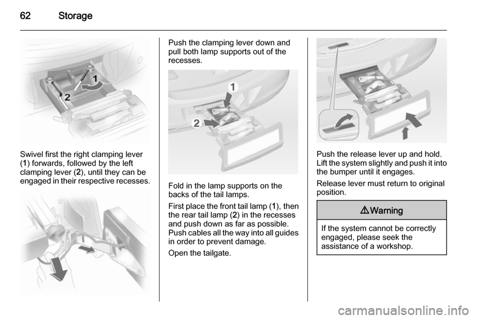
Swivel first the right clamping lever
( 1 ) forwards, followed by the left
clamping lever ( 2), until they can be
engaged in their respective recesses.
Push the clamping lever down and
pull both lamp supports out of the recesses.
Fold in the lamp supports on the
backs of the tail lamps.
First place the front tail lamp ( 1), then
the rear tail lamp ( 2) in the recesses
and push down as far as possible. Push cables all the way into all guides
in order to prevent damage.
Open the tailgate.
Push the release lever up and hold.
Lift the system slightly and push it into the bumper until it engages.
Release lever must return to original
position.
9 Warning
If the system cannot be correctly
engaged, please seek the
assistance of a workshop.
Page 68 of 231
66StorageRear floor storage cover
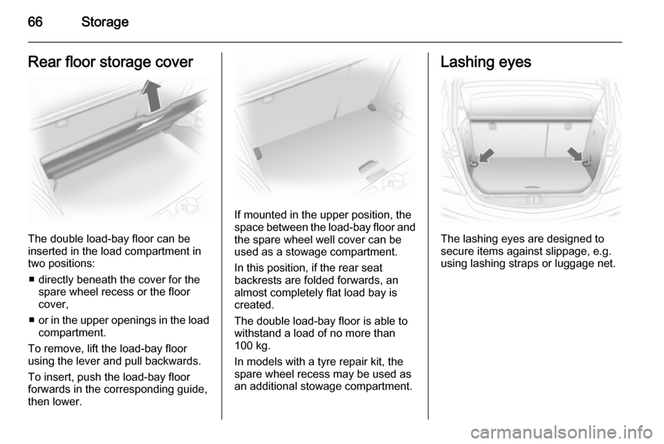
The double load-bay floor can be
inserted in the load compartment in
two positions:
■ directly beneath the cover for the spare wheel recess or the floor
cover,
■ or in the upper openings in the load
compartment.
To remove, lift the load-bay floor
using the lever and pull backwards.
To insert, push the load-bay floor
forwards in the corresponding guide,
then lower.
If mounted in the upper position, the
space between the load-bay floor and
the spare wheel well cover can be
used as a stowage compartment.
In this position, if the rear seat
backrests are folded forwards, an
almost completely flat load bay is
created.
The double load-bay floor is able to
withstand a load of no more than
100 kg.
In models with a tyre repair kit, the spare wheel recess may be used asan additional stowage compartment.
Lashing eyes
The lashing eyes are designed to
secure items against slippage, e.g.
using lashing straps or luggage net.
Page 104 of 231
102LightingFront fog lights
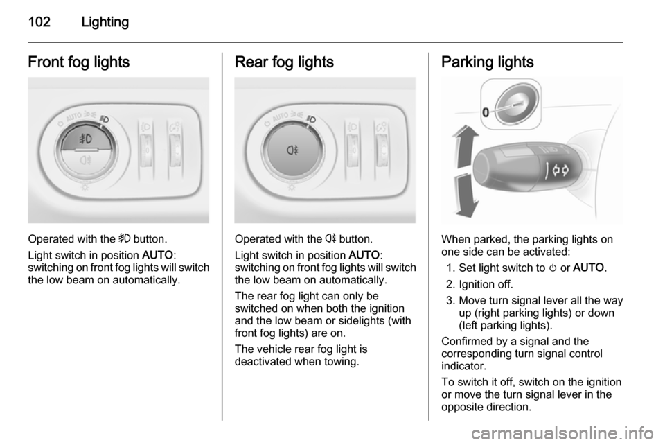
Operated with the > button.
Light switch in position AUTO:
switching on front fog lights will switch the low beam on automatically.
Rear fog lights
Operated with the r button.
Light switch in position AUTO:
switching on front fog lights will switch the low beam on automatically.
The rear fog light can only be
switched on when both the ignition and the low beam or sidelights (with
front fog lights) are on.
The vehicle rear fog light is
deactivated when towing.
Parking lights
When parked, the parking lights on
one side can be activated:
1. Set light switch to m or AUTO .
2. Ignition off.
3. Move turn signal lever all the way up (right parking lights) or down
(left parking lights).
Confirmed by a signal and the
corresponding turn signal control
indicator.
To switch it off, switch on the ignition
or move the turn signal lever in the
opposite direction.
Page 112 of 231
110Climate control
Notice
If the temperature is set to Lo or Hi,
an Autostop will be inhibited.
If the temperature is set to Lo or Hi
while the engine is in an Autostop,
the engine will restart automatically.
Stop-start system 3 116.
Fan speed The selected fan speed is indicated
with x and the number in the display.
If the fan is switched off the air
conditioning is also deactivated.
To return to automatic mode: Press AUTO button.
Demisting and defrosting the
windows
Press the V button. V appears in
the display.
Temperature and air distribution are
set automatically and the fan runs at
a high speed.
To return to automatic mode: Press button V or AUTO .
Switch on heated rear window Ü.Notice
If the V button is pressed with fan
switched on while the engine is
running, an Autostop will be inhibited
until the V button is pressed again.
If the V button is pressed with fan
switched on while the engine is in an Autostop, the engine will restart
automatically.
Stop-start system 3 116.
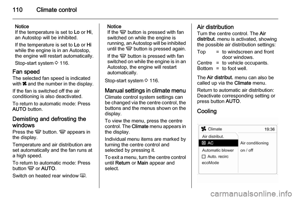
Manual settings in climate menu Climate control system settings can
be changed via the centre control, the
buttons and the menus shown on the
display.
To view the menu, press the centre
control. The Climate menu appears in
the display.
Individual menu items are marked by
turning the centre control and
selected by pressing it.
To exit a menu, turn the centre control until Return or Main appear and
select.Air distribution
Turn the centre control. The Air
distribut. menu is activated, showing
the possible air distribution settings:Top=to windscreen and front
door windows.Centre=to vehicle occupants.Bottom=to foot well.
The Air distribut. menu can also be
called up via the Climate menu.
Return to automatic air distribution:
Deactivate corresponding setting or press button AUTO.
Cooling
Page 115 of 231
Climate control113
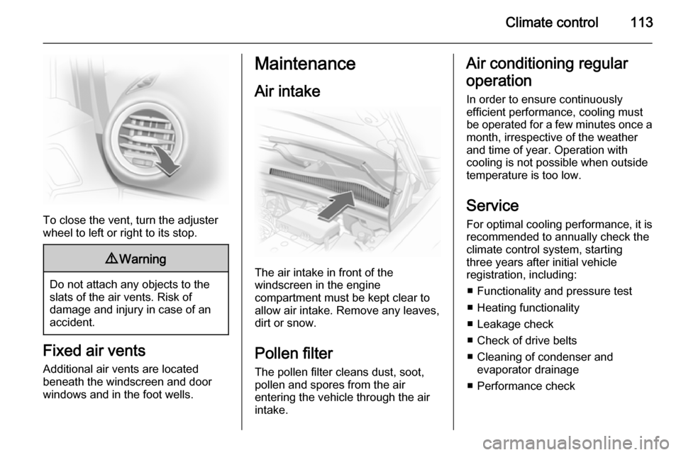
To close the vent, turn the adjuster
wheel to left or right to its stop.
9 Warning
Do not attach any objects to the
slats of the air vents. Risk of
damage and injury in case of an
accident.
Fixed air vents
Additional air vents are located
beneath the windscreen and door windows and in the foot wells.
Maintenance
Air intake
The air intake in front of the
windscreen in the engine
compartment must be kept clear to
allow air intake. Remove any leaves,
dirt or snow.
Pollen filter
The pollen filter cleans dust, soot,
pollen and spores from the air
entering the vehicle through the air
intake.
Air conditioning regular
operation In order to ensure continuously
efficient performance, cooling must
be operated for a few minutes once a
month, irrespective of the weather
and time of year. Operation with
cooling is not possible when outside
temperature is too low.
Service For optimal cooling performance, it isrecommended to annually check the
climate control system, starting
three years after initial vehicle
registration, including:
■ Functionality and pressure test■ Heating functionality
■ Leakage check
■ Check of drive belts
■ Cleaning of condenser and evaporator drainage
■ Performance check
Page 118 of 231
116Driving and operating
During an Autostop, the engine can
be started by depressing the clutch
pedal.
Starting the vehicle at low
temperatures
The start of the engine without
additional heaters is possible down to -25 °С for diesel engines and -30 °C
for petrol engines. Required is an
engine oil with the correct viscosity,
the correct fuel, performed services
and a sufficiently charged battery.
With temperatures below -30 °C the
automatic transmission need a
warming phase of approx. 5 minutes. The selector lever must be in position
P .
Turbo engine warm-up Upon start-up, engine available
torque may be limited for a short time,
especially when the engine
temperature is cold. The limitation is
to allow the lubrication system to fully protect the engine.Overrun cut-off
The fuel supply is automatically cut off
during overrun, i.e. when the vehicle
is driven with a gear engaged but accelerator is released. Overrun cut-
off is deactivated if catalytic converter
temperature is high.
Stop-start system
The stop-start system helps to save
fuel and to reduce the exhaust
emissions. When conditions allow, it
switches off the engine as soon as the
vehicle is at a low speed or at a
standstill, e.g. at a traffic light or in a
traffic jam. It starts the engine
automatically as soon as the clutch is
depressed. A battery sensor ensures
that an Autostop is only performed if
the battery is sufficiently charged for a restart.
Activation The stop-start system is available as
soon as the engine is started, the
vehicle starts-off and the conditions
as stated below in this section are
fulfilled.Deactivation
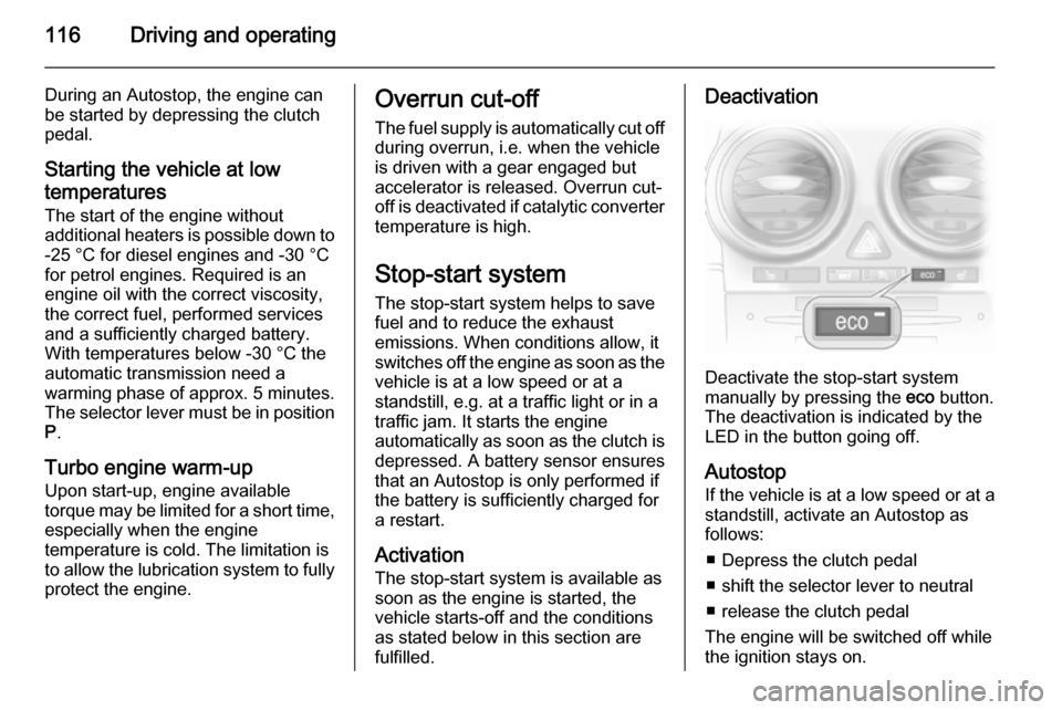
Deactivate the stop-start system
manually by pressing the eco button.
The deactivation is indicated by the
LED in the button going off.
Autostop
If the vehicle is at a low speed or at a standstill, activate an Autostop as
follows:
■ Depress the clutch pedal
■ shift the selector lever to neutral
■ release the clutch pedal
The engine will be switched off while the ignition stays on.
Page 127 of 231

Driving and operating125
Always move the selector lever in the
appropriate direction as far as it will
go. Upon release, it automatically
returns to the centre position.N=Neutral position.A=Switch between automatic and
manual mode. The
transmission display shows A
or M.R=Reverse gear. Engage only
when vehicle is stationary.+=Shift to a higher gear.-=Shift to a lower gear.
Starting off
Depress the foot brake and move the
selector lever to A, + or -. The
transmission is in automatic mode
and first gear is engaged. If R is
selected, reverse gear is engaged.
The vehicle starts to move when the
brake is released.
To start off without depressing the
foot brake, accelerate immediately
after engaging a gear.
If neither the accelerator nor the
brake pedal are depressed, no gear
is engaged and A or R flashes for a
brief time in the display.
Stopping the vehicle In A, first gear is engaged and the
clutch is released when the vehicle is
stopped. In R, reverse gear remains
engaged.
Engine braking
Automatic mode
When driving downhill, the manual
transmission automated does not
shift into higher gears until a fairly
high engine speed has been reached. It shifts down in good time when
braking.
Manual mode
To utilise the engine braking effect,
select a lower gear in good time when
driving downhill.Rocking the vehicle
Rocking the vehicle is only
permissible if the vehicle is stuck in
sand, mud or snow. Move the selector
lever between R and A (or + or -) in a
repeat pattern. Do not race the engine and avoid sudden acceleration.
Parking
Apply the parking brake. The most recently engaged gear (see
transmission display) remains
engaged. With N, no gear is engaged.
When the ignition is switched off the
transmission no longer responds to
movement of the selector lever.
Manual mode
If a higher gear is selected when the
engine speed is too low, or a lower
gear when the speed is too high, the
shift is not executed. This prevents
the engine from running at too low or
too high an engine speed.
If engine speed is too low, the
transmission automatically shifts to a
lower gear.
Page 130 of 231
128Driving and operating
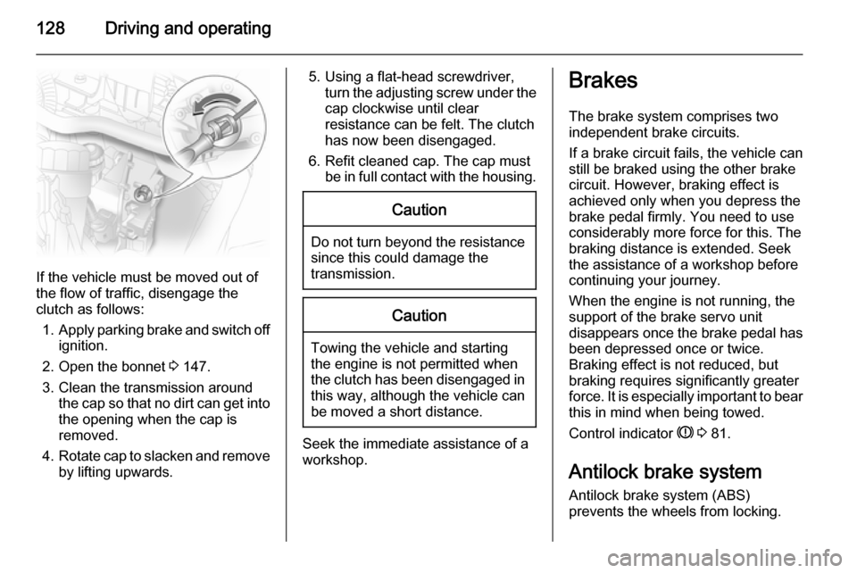
If the vehicle must be moved out of
the flow of traffic, disengage the
clutch as follows:
1. Apply parking brake and switch off
ignition.
2. Open the bonnet 3 147.
3. Clean the transmission around the cap so that no dirt can get into
the opening when the cap is
removed.
4. Rotate cap to slacken and remove
by lifting upwards.
5. Using a flat-head screwdriver,
turn the adjusting screw under the
cap clockwise until clear
resistance can be felt. The clutch
has now been disengaged.
6. Refit cleaned cap. The cap must be in full contact with the housing.Caution
Do not turn beyond the resistancesince this could damage the
transmission.
Caution
Towing the vehicle and starting
the engine is not permitted when
the clutch has been disengaged in this way, although the vehicle can
be moved a short distance.
Seek the immediate assistance of a
workshop.
Brakes
The brake system comprises two
independent brake circuits.
If a brake circuit fails, the vehicle can
still be braked using the other brake
circuit. However, braking effect is
achieved only when you depress the
brake pedal firmly. You need to use
considerably more force for this. The
braking distance is extended. Seek
the assistance of a workshop before continuing your journey.
When the engine is not running, the
support of the brake servo unit
disappears once the brake pedal has
been depressed once or twice.
Braking effect is not reduced, but
braking requires significantly greater
force. It is especially important to bear this in mind when being towed.
Control indicator R 3 81.
Antilock brake system Antilock brake system (ABS)
prevents the wheels from locking.