tow VAUXHALL CORSA 2017 Owner's Guide
[x] Cancel search | Manufacturer: VAUXHALL, Model Year: 2017, Model line: CORSA, Model: VAUXHALL CORSA 2017Pages: 267, PDF Size: 7.82 MB
Page 186 of 267
184Driving and operatingThe permissible gross train weight
must not be exceeded. This weight is
specified on the identification plate
3 239.
Vertical coupling load The vertical coupling load is the load
exerted by the trailer on the coupling
ball. It can be varied by changing the
weight distribution when loading the
trailer.Petrol and diesel engines
The maximum permissible vertical
coupling load (55 kg) is specified on
the towing equipment identification
plate and in the vehicle documents.
Always aim for the maximum load,
especially in the case of heavy
trailers. The vertical coupling load
should never fall below 25 kg.Engine B14XEL LPG
The maximum permissible vertical
coupling load (45 kg) is specified on
the towing equipment identification
plate and in the vehicle documents.
Always aim for the maximum load,
especially in the case of heavy
trailers. The vertical coupling load
should never fall below 25 kg.Rear axle loadPetrol and diesel engines
When the trailer is coupled and the
towing vehicle fully loaded, the
permissible rear axle load (see
identification plate or vehicle
documents) for passenger vehicles
may be exceeded by 70 kg for the 5-
door vehicle and 60 kg for the 3-door
vehicle, the gross vehicle weight
rating by 55 kg.Engine B14XEL LPG
When the trailer is coupled and the
towing vehicle fully loaded, the
permissible rear axle load (see
identification plate or vehicle
documents) for passenger vehicles
may be exceeded by 70 kg for the 5-
door vehicle and 70 kg for the 3-door
vehicle and the gross vehicle weight
rating by 45 kg.Delivery van
When the trailer is coupled and the
towing vehicle fully loaded, the
permissible rear axle load (see
identification plate or vehicle
documents) for passenger vehicles
may be exceeded by 60 kg and the
gross vehicle weight rating by 55 kg.General
If the permitted rear axle load is
exceeded a maximum speed of
60 mph applies. If lower national
maximum speeds are specified for
trailer operation, they must be
complied with.
Towing equipmentCaution
When operating without a trailer,
remove the coupling ball bar.
Stowage of coupling ball bar
The coupling ball bar is stowed in a
bag in the spare wheel well and
secured to the lashing eyes in the
load compartment.
Page 187 of 267
Driving and operating185
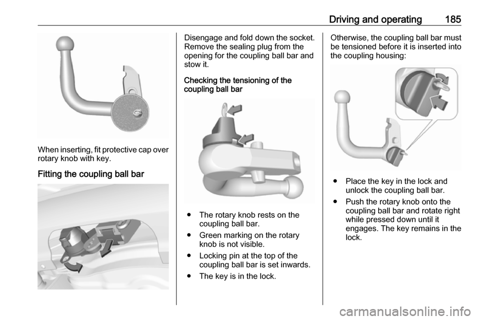
When inserting, fit protective cap over
rotary knob with key.
Fitting the coupling ball bar
Disengage and fold down the socket. Remove the sealing plug from the
opening for the coupling ball bar and
stow it.
Checking the tensioning of the
coupling ball bar
● The rotary knob rests on the
coupling ball bar.
● Green marking on the rotary knob is not visible.
● Locking pin at the top of the coupling ball bar is set inwards.
● The key is in the lock.
Otherwise, the coupling ball bar must be tensioned before it is inserted into
the coupling housing:
● Place the key in the lock and unlock the coupling ball bar.
● Push the rotary knob onto the coupling ball bar and rotate right
while pressed down until it
engages. The key remains in the
lock.
Page 189 of 267
Driving and operating1879Warning
Towing a trailer is permitted only
when a coupling ball bar is fitted correctly. If the coupling ball bardoes not engage correctly, seekthe assistance of a workshop.
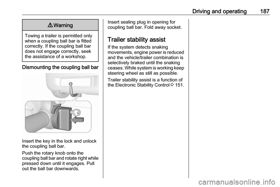
Dismounting the coupling ball bar
Insert the key in the lock and unlock
the coupling ball bar.
Push the rotary knob onto the
coupling ball bar and rotate right while pressed down until it engages. Pull
out the ball bar downwards.
Insert sealing plug in opening for
coupling ball bar. Fold away socket.
Trailer stability assist
If the system detects snaking
movements, engine power is reduced
and the vehicle/trailer combination is
selectively braked until the snaking ceases. While system is working keep
steering wheel as still as possible.
Trailer stability assist is a function of
the Electronic Stability Control 3 151.
Page 190 of 267

188Vehicle careVehicle careGeneral Information...................189
Accessories and vehicle modifications .......................... 189
Vehicle storage ........................189
End-of-life vehicle recovery .....190
Vehicle checks ........................... 190
Performing work ......................190
Bonnet ..................................... 190
Engine oil ................................. 191
Engine coolant ......................... 192
Washer fluid ............................ 194
Brakes ..................................... 194
Brake fluid ............................... 194
Vehicle battery ......................... 194
Diesel fuel system bleeding .....196
Wiper blade replacement ........196
Bulb replacement .......................197
Halogen headlights ..................197
Xenon headlights .....................200
Fog lights ................................. 201
Front turn signal lights .............201
Tail lights ................................. 201
Side turn signal lights ..............203
Centre high-mounted brake light ......................................... 204Number plate light...................204
Interior lights ............................ 205
Instrument panel illumination ...205
Electrical system ........................205
Fuses ....................................... 205
Engine compartment fuse box . 206
Instrument panel fuse box .......208
Vehicle tools .............................. 210
Tools ........................................ 210
Wheels and tyres .......................211
Winter tyres ............................. 211
Tyre designations ....................211
Tyre pressure .......................... 212
Tyre pressure monitoring system .................................... 213
Tread depth ............................. 217
Changing tyre and wheel size . 217
Wheel covers ........................... 218
Tyre chains .............................. 218
Tyre repair kit .......................... 218
Wheel changing .......................224
Spare wheel ............................ 226
Jump starting ............................. 228
Towing ....................................... 230
Towing the vehicle ...................230
Towing another vehicle ...........231Appearance care .......................232
Exterior care ............................ 232
Interior care ............................. 234
Page 212 of 267
210Vehicle careNo.Circuit34–35Tyre repair kit36–37Rear wiper38Cigarette lighter39Power windows/Sunroof/Auto‐
matic transmission display40–Vehicle tools
Tools
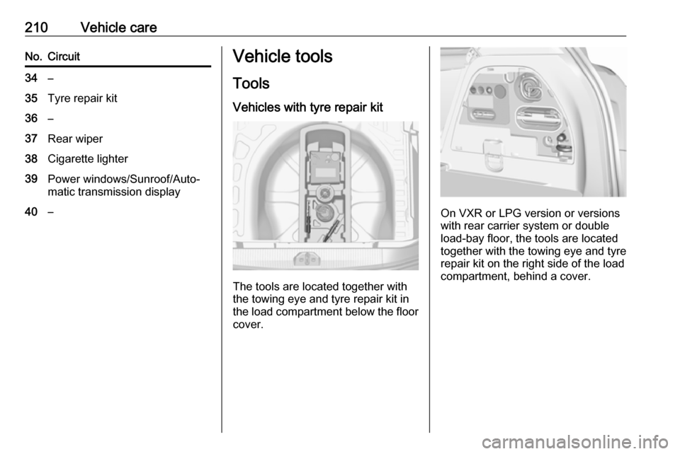
Vehicles with tyre repair kit
The tools are located together with
the towing eye and tyre repair kit in the load compartment below the floor cover.
On VXR or LPG version or versions
with rear carrier system or double
load-bay floor, the tools are located
together with the towing eye and tyre
repair kit on the right side of the load
compartment, behind a cover.
Page 221 of 267

Vehicle care219Do not remove foreign bodies from
the tyres.
Tyre damage exceeding 4 mm or that
is at the tyre's side wall near the rim
cannot be repaired with the tyre repair kit.9 Warning
Do not drive faster than 50 mph.
Do not use for a lengthy period.
Steering and handling may be
affected.
If you have a flat tyre:
Apply the parking brake and engage
first gear, reverse gear or P.
The tyre repair kit is stowed in the load
compartment.
Depending on the equipment, the tyre repair kit is in a compartment in the
right sidewall or in a compartment
under the floor cover.
Vehicles with tyre repair kit under
the floor cover
1. Take the tyre repair kit from the compartment.
2. Remove the compressor.
3. Remove the electrical connection cable and air hose from the
stowage compartments on the
underside of the compressor.
Page 223 of 267
Vehicle care221Drain excess tyre pressure with
the button over the pressure
indicator.
Do not run the compressor for
longer than ten minutes.
14. Detach the tyre repair kit. Push catch on bracket to remove
sealant bottle from bracket. Screw the tyre inflation hose to the freeconnection of the sealant bottle.
This prevents sealant from
escaping. Stow tyre repair kit in
load compartment.
15. Remove any excess sealant using a cloth.
16. Take the label indicating maximum permitted speed from
the sealant bottle and affix in the
driver's field of view.
17. Continue driving immediately so that sealant is evenly distributedin the tyre. After driving approx.
six miles (but no more than ten
minutes), stop and check tyre
pressure. Screw compressor air
hose directly onto tyre valve and
compressor when doing this.
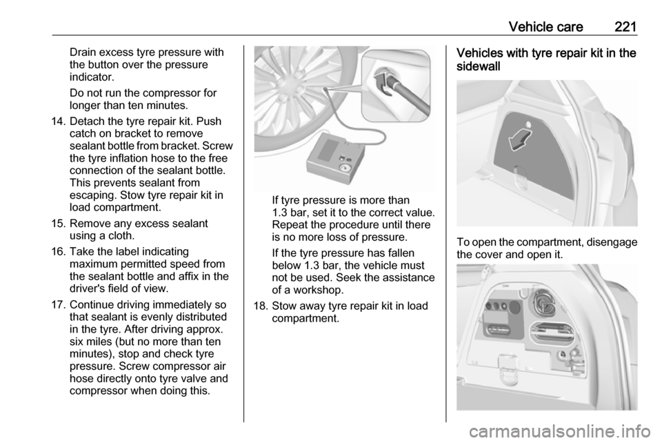
If tyre pressure is more than 1.3 bar , set it to the correct value.
Repeat the procedure until there
is no more loss of pressure.
If the tyre pressure has fallen
below 1.3 bar, the vehicle must
not be used. Seek the assistance
of a workshop.
18. Stow away tyre repair kit in load compartment.
Vehicles with tyre repair kit in the
sidewall
To open the compartment, disengage the cover and open it.
Page 225 of 267

Vehicle care22310. All of the sealant is pumped intothe tyre. Then the tyre is inflated.
11. The prescribed tyre pressure should be obtained within ten
minutes.
Tyre pressure 3 251.
When the correct pressure is
obtained, switch off the
compressor by pressing the on/off switch again.
If the prescribed tyre pressure is
not obtained within ten minutes,
remove the tyre repair kit. Move
the vehicle one tyre rotation.
Reattach the tyre repair kit and
continue the filling procedure for
ten minutes. If the prescribed tyre
pressure is still not obtained, the
tyre is too badly damaged. Seek
the assistance of a workshop.
Release excess tyre pressure
using ].
Do not run the compressor for
longer than ten minutes.
12. Push catch on bracket to remove sealant bottle from bracket. Screwthe tyre inflation hose to the free
connection of the sealant bottle.This prevents sealant from
escaping. Stow tyre repair kit in
load compartment.
13. Remove any excess sealant using a cloth.
14. Take the label indicating maximum permitted speed from
the sealant bottle and affix in the
driver's field of view.
15. Continue driving immediately so that sealant is evenly distributed
in the tyre. After driving approx.
six miles (but no more than ten
minutes), stop and check tyre
pressure. Screw compressor air
hose directly onto tyre valve and
compressor when doing this.
If tyre pressure is more than
1.3 bar , set it to the correct value.
Repeat the procedure until there
is no more loss of pressure.
If the tyre pressure has fallen
below 1.3 bar, the vehicle must
not be used. Seek the assistance
of a workshop.
16. Stow away tyre repair kit in load compartment.General information
Notice
The driving characteristics of the repaired tyre are severely affected,
therefore have this tyre replaced.
If unusual noise is heard or the
compressor becomes hot, turn
compressor off for at least
30 minutes.
The built-in safety valve opens at a
pressure of seven bar (102 psi).
Note the expiry date of the kit. After
this date its sealing capability is no
longer guaranteed. Pay attention to
storage information on sealant
bottle.
Replace the used sealant bottle. Dispose of the bottle as prescribed
by applicable laws.
The compressor and sealant can be used from approx. -30 °C.
The adapters supplied can be used
to pump up other items e.g.
footballs, air mattresses, inflatable
dinghies etc. They are located on the underside of the compressor. To
remove, screw on compressor air
hose and withdraw adapter.
Page 228 of 267
226Vehicle careInstall wheel bolt caps or centre
cap on alloy wheel.
11. Install vehicle jacking point cover.
12. Stow and secure the replaced wheel, the vehicle tools 3 210 and
the adapter for the locking wheel
bolts 3 56.
13. Check the tyre pressure of the installed tyre and the wheel bolt
torque as soon as possible.
Have the defective tyre renewed or
repaired as soon as possible.
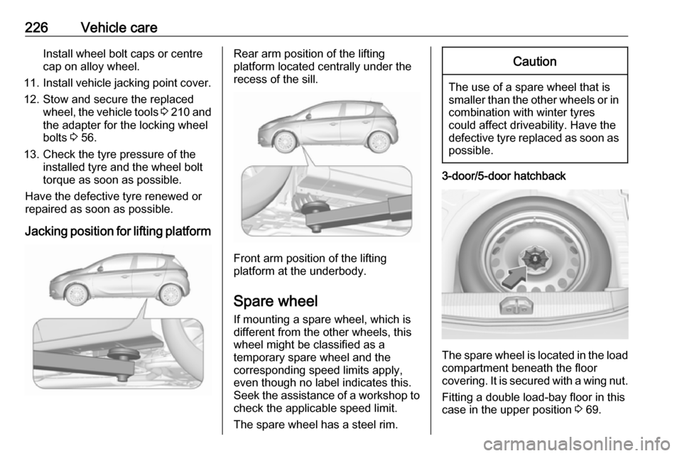
Jacking position for lifting platformRear arm position of the lifting
platform located centrally under the
recess of the sill.
Front arm position of the lifting
platform at the underbody.
Spare wheel If mounting a spare wheel, which is
different from the other wheels, this
wheel might be classified as a
temporary spare wheel and the
corresponding speed limits apply,
even though no label indicates this.
Seek the assistance of a workshop to
check the applicable speed limit.
The spare wheel has a steel rim.
Caution
The use of a spare wheel that is smaller than the other wheels or in combination with winter tyres
could affect driveability. Have the defective tyre replaced as soon as
possible.
3-door/5-door hatchback
The spare wheel is located in the load
compartment beneath the floor
covering. It is secured with a wing nut.
Fitting a double load-bay floor in this
case in the upper position 3 69.
Page 229 of 267
Vehicle care227To remove, unscrew wing nut, lift
spare wheel, move to a vertical
position and remove from above.
When stowing the replaced wheel or
the temporary spare wheel back in
the spare wheel well, always secure
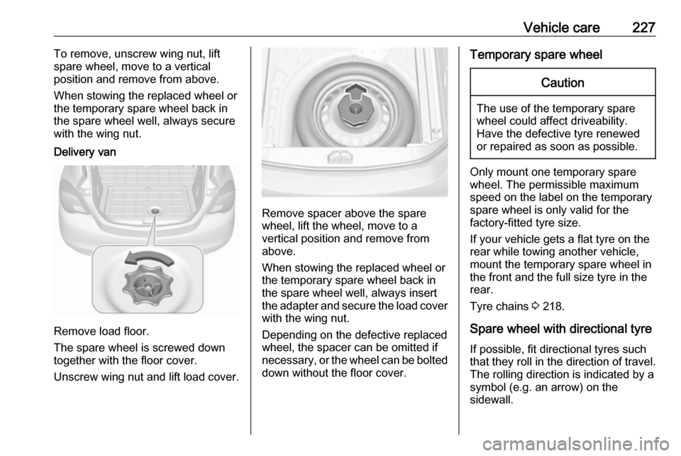
with the wing nut.Delivery van
Remove load floor.
The spare wheel is screwed down
together with the floor cover.
Unscrew wing nut and lift load cover.
Remove spacer above the spare
wheel, lift the wheel, move to a
vertical position and remove from
above.
When stowing the replaced wheel or
the temporary spare wheel back in
the spare wheel well, always insert
the adapter and secure the load cover with the wing nut.
Depending on the defective replaced
wheel, the spacer can be omitted if
necessary, or the wheel can be bolted down without the floor cover.
Temporary spare wheelCaution
The use of the temporary spare
wheel could affect driveability.
Have the defective tyre renewed
or repaired as soon as possible.
Only mount one temporary spare
wheel. The permissible maximum
speed on the label on the temporary
spare wheel is only valid for the
factory-fitted tyre size.
If your vehicle gets a flat tyre on the
rear while towing another vehicle,
mount the temporary spare wheel in
the front and the full size tyre in the
rear.
Tyre chains 3 218.
Spare wheel with directional tyre If possible, fit directional tyres such
that they roll in the direction of travel.
The rolling direction is indicated by a
symbol (e.g. an arrow) on the
sidewall.