tyre pressure VAUXHALL CORSA F 2018 Owner's Guide
[x] Cancel search | Manufacturer: VAUXHALL, Model Year: 2018, Model line: CORSA F, Model: VAUXHALL CORSA F 2018Pages: 271, PDF Size: 7.86 MB
Page 220 of 271

218Vehicle care3. On vehicles with automatictransmission: set the selector
lever to P.
On vehicles with manual
transmission automated: Keep
brake pedal depressed. Move and hold the selector lever for five
seconds to position N until P is
displayed in the Driver
Information Centre. P indicates
that the tyre pressure sensor
matching process can be started.
On vehicles with manual
transmission: select neutral.
4. Use MENU on the turn signal
lever to select the Vehicle
Information Menu ? in the
Driver Information Centre.
5. Turn the adjuster wheel to scroll to
the tyre pressure menu.
Midlevel display:
Uplevel display:
6. Press SET/CLR to begin the
sensor matching process. A
message requesting acceptance
of the process should be
displayed.
7. Press SET/CLR again to confirm
the selection. The horn sounds
twice to indicate that the receiver
is in relearn mode.
8. Start with the left side front wheel.
9. Place the relearn tool against the tyre sidewall, near the valve stem.Then press the button to activate
the tyre pressure sensor. A horn
chirp confirms that the sensor
identification code has been
matched to this wheel position.
10. Proceed to the right side front wheel, and repeat the procedure
in Step 9.
11. Proceed to the right side rear wheel, and repeat the procedure
in Step 9.
12. Proceed to the left side rear wheel, and repeat the procedure
in Step 9. The horn sounds twice
to indicate that the sensor
identification code has been
Page 221 of 271

Vehicle care219matched to the left side rear
wheel, and the tyre pressure
sensor matching process is no
longer active.
13. Turn off the ignition.
14. Set all four tyres to the recommended air pressure level
as indicated on the tyre pressure
information label.
15. Ensure the tyre loading status is set according to the selected
pressure 3 97.
Tread depth
Check tread depth at regular
intervals.
Tyres should be replaced for safety
reasons at a tread depth of 2-3 mm
(4 mm for winter tyres).
For safety reasons it is recommended
that the tread depth of the tyres on
one axle should not vary by more than 2 mm.
The legally permissible minimum
tread depth (1.6 mm) has been
reached when the tread has worn
down as far as one of the tread wear
indicators (TWI). Their position is
indicated by markings on the
sidewall.
Tyres age, even if they are not used.
We recommend tyre replacement
every six years.
Changing tyre and wheel size
If tyres of a different size than those
fitted at the factory are used, it may be necessary to reprogramme the
speedometer as well as the nominal
tyre pressure and to make other
vehicle modifications.
After converting to a different tyre
size, have the label with tyre
pressures replaced.
Tyre pressure monitoring system
3 215.Caution
When converting to wheels with
14 inch diameter, the ground
clearance will be reduced. This
must be considered when passing
over obstacles.
9 Warning
The use of unsuitable tyres or
wheels may lead to accidents and will invalidate the vehicle
operating permit.
Page 222 of 271
220Vehicle careWheel coversWheel covers and tyres that are
factory approved for the respective
vehicle and comply with all of the
relevant wheel and tyre combination
requirements must be used.
If the wheel covers and tyres used are
not factory approved, the tyres must
not have a rim protection ridge.
Wheel covers must not impair brake
cooling.9 Warning
Use of unsuitable tyres or wheel
covers could lead to sudden
pressure loss and thereby
accidents.
Steel wheels: When using locking
wheel nuts don't attach wheel covers.
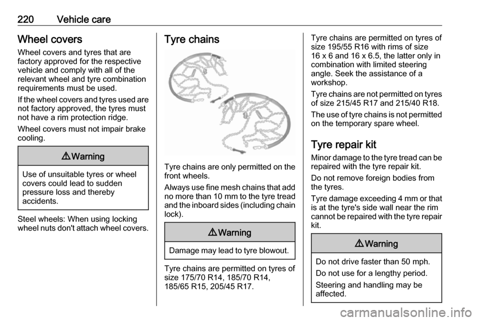
Tyre chains
Tyre chains are only permitted on the
front wheels.
Always use fine mesh chains that add no more than 10 mm to the tyre tread
and the inboard sides (including chain lock).
9 Warning
Damage may lead to tyre blowout.
Tyre chains are permitted on tyres of
size 175/70 R14, 185/70 R14,
185/65 R15, 205/45 R17.
Tyre chains are permitted on tyres of
size 195/55 R16 with rims of size
16 x 6 and 16 x 6.5, the latter only in combination with limited steering
angle. Seek the assistance of a
workshop.
Tyre chains are not permitted on tyres of size 215/45 R17 and 215/40 R18.
The use of tyre chains is not permitted on the temporary spare wheel.
Tyre repair kit Minor damage to the tyre tread can be
repaired with the tyre repair kit.
Do not remove foreign bodies from
the tyres.
Tyre damage exceeding 4 mm or that is at the tyre's side wall near the rim
cannot be repaired with the tyre repair kit.9 Warning
Do not drive faster than 50 mph.
Do not use for a lengthy period.
Steering and handling may be
affected.
Page 224 of 271

222Vehicle care9. Connect the compressor plug tothe power outlet or cigarette
lighter socket.
To avoid discharging the battery,
we recommend running the
engine.
10. Set the rocker switch on the compressor to I. The tyre is filled
with sealant.
11. The compressor pressure gauge briefly indicates up to six bar
whilst the sealant bottle is
emptying (approx. 30 seconds).
Then the pressure starts to drop.
12. All of the sealant is pumped into the tyre. Then the tyre is inflated.
13. The prescribed tyre pressureshould be obtained within ten
minutes.
Tyre pressure 3 254.
When the correct pressure is
obtained, switch off the
compressor.
If the prescribed tyre pressure is
not obtained within ten minutes,
remove the tyre repair kit. Move
the vehicle one tyre rotation.
Reattach the tyre repair kit and
continue the filling procedure for
ten minutes. If the prescribed tyre
pressure is still not obtained, the
tyre is too badly damaged. Seek
the assistance of a workshop.
Drain excess tyre pressure with
the button over the pressure indicator.
Do not run the compressor for
longer than ten minutes.
14. Detach the tyre repair kit. Push catch on bracket to remove
sealant bottle from bracket. Screw the tyre inflation hose to the freeconnection of the sealant bottle.
This prevents sealant from
escaping. Stow tyre repair kit in
load compartment.
15. Remove any excess sealant using a cloth.
16. Take the label indicating maximum permitted speed from
the sealant bottle and affix in the
driver's field of view.
17. Continue driving immediately so that sealant is evenly distributedin the tyre. After driving approx.
six miles (but no more than ten
minutes), stop and check tyre
pressure. Screw compressor air
hose directly onto tyre valve and
compressor when doing this.
Page 225 of 271

Vehicle care223
If tyre pressure is more than
1.3 bar , set it to the correct value.
Repeat the procedure until there
is no more loss of pressure.
If the tyre pressure has fallen
below 1.3 bar, the vehicle must
not be used. Seek the assistance
of a workshop.
18. Stow away tyre repair kit in load compartment.
Vehicles with tyre repair kit in the
sidewall
To open the compartment, disengage the cover and open it.
1. Take the sealant bottle and bracket with air hose from the
insert.
2. Detach air hose from bracket and screw onto sealant bottle
connection.
Page 226 of 271

224Vehicle care
3. Position the sealant bottle on thebracket. Make sure that the bottle
does not fall.
4. Unscrew valve cap from defective
tyre.
5. Screw tyre inflation hose to valve.
6. Screw air hose onto compressor connection.
7. Switch on ignition. To avoid discharging the battery,
we recommend running the
engine.
8. Press on/off switch on the compressor. The tyre is filled withsealant.
9. The compressor pressure gauge briefly indicates up to six bar
whilst the sealant bottle is
emptying (approx. 30 seconds).
Then the pressure starts to drop.
10. All of the sealant is pumped into the tyre. Then the tyre is inflated.
11. The prescribed tyre pressure should be obtained within ten
minutes.
Tyre pressure 3 254.
When the correct pressure is
obtained, switch off the
compressor by pressing the on/off
switch again.
If the prescribed tyre pressure is
not obtained within ten minutes,
remove the tyre repair kit. Move
the vehicle one tyre rotation.
Reattach the tyre repair kit and
continue the filling procedure for ten minutes. If the prescribed tyre pressure is still not obtained, the
tyre is too badly damaged. Seek
the assistance of a workshop.
Release excess tyre pressure
using ].
Do not run the compressor for
longer than ten minutes.
12. Push catch on bracket to remove sealant bottle from bracket. Screw
the tyre inflation hose to the free
connection of the sealant bottle.
Page 227 of 271

Vehicle care225This prevents sealant from
escaping. Stow tyre repair kit in
load compartment.
13. Remove any excess sealant using a cloth.
14. Take the label indicating maximum permitted speed from
the sealant bottle and affix in the
driver's field of view.
15. Continue driving immediately so that sealant is evenly distributedin the tyre. After driving approx.
six miles (but no more than ten
minutes), stop and check tyre
pressure. Screw compressor air
hose directly onto tyre valve and
compressor when doing this.
If tyre pressure is more than 1.3 bar , set it to the correct value.
Repeat the procedure until there
is no more loss of pressure.
If the tyre pressure has fallen
below 1.3 bar, the vehicle must
not be used. Seek the assistance
of a workshop.
16. Stow away tyre repair kit in load compartment.General information
Notice
The driving characteristics of the
repaired tyre are severely affected, therefore have this tyre replaced.
If unusual noise is heard or the
compressor becomes hot, turn
compressor off for at least
30 minutes.
The built-in safety valve opens at a
pressure of seven bar (102 psi).
Note the expiry date of the kit. After
this date its sealing capability is no
longer guaranteed. Pay attention to
storage information on sealant
bottle.
Replace the used sealant bottle. Dispose of the bottle as prescribed
by applicable laws.
The compressor and sealant can be
used from approx. -30 °C.
The adapters supplied can be used
to pump up other items e.g.
footballs, air mattresses, inflatable
dinghies etc. They are located on the underside of the compressor. To
remove, screw on compressor air hose and withdraw adapter.Wheel changing
Make the following preparations and
observe the following information:
● Park the vehicle on a level, firm and non-skid surface. The front
wheels must be in the straight- ahead position.
● Apply the parking brake and engage first gear, reverse gear or
P .
● Never change more than one wheel at once.
● Use the jack only to change wheels in case of puncture, not
for seasonal winter or summer
tyre change.
● The jack is maintenance-free.
● If the ground on which the vehicle
is standing is soft, a solid board
(max. 1 cm thick) should be
placed under the jack.
● Take heavy objects out of the vehicle before jacking up.
● No people or animals may be in the vehicle when it is jacked-up.
● Never crawl under a jacked-up vehicle.
Page 229 of 271

Vehicle care227
4. Set the jack to the necessaryheight. Position it directly below
the jacking point in a manner that
prevents it from slipping.
Attach jack handle and with the
jack correctly aligned rotate handle until wheel is clear of theground.
5. Unscrew the wheel bolts.
6. Change the wheel.
7. Screw on the wheel bolts.
8. Lower vehicle.
9. Install the wheel wrench ensuring that it is securely located and
tighten each bolt in a crosswise
sequence. Tightening torque is
110 Nm.
10. Align the valve hole in the wheel cover of the steel wheel with the
tyre valve before installing.
Install wheel bolt caps or centre
cap on alloy wheel.
11. Install vehicle jacking point cover.
12. Stow and secure the replaced wheel, the vehicle tools 3 212 and
the adapter for the locking wheel
bolts 3 56.
13. Check the tyre pressure of the installed tyre and the wheel bolt
torque as soon as possible.Have the defective tyre renewed or
repaired as soon as possible.
Jacking position for lifting platform
Rear arm position of the lifting
platform located centrally under the
recess of the sill.
Page 237 of 271

Vehicle care235Remove dirt residues from smearing
wiper blades by using a soft cloth and
window cleaner. Also make sure to
remove any residues such as wax,
insect residues and similar from the
window.
Ice residues, pollution and continuous wiping on dry windows will damage or
even destroy the wiper blades.
Sunroof Never clean with solvents or abrasive
agents, fuels, aggressive media (e.g.
paint cleaner, acetone-containing solutions etc.), acidic or highly
alkaline media or abrasive pads. Do
not apply wax or polishing agents to
the sunroof.
Wheels and tyres Do not use high-pressure jet
cleaners.
Clean rims with a pH-neutral wheel
cleaner.
Rims are painted and can be treated
with the same agents as the body.Paintwork damage
Rectify minor paintwork damage with
a touch-up pen before rust forms.
Have more extensive damage or rust areas repaired by a workshop.
Underbody
Some areas of the vehicle underbody
have a PVC undercoating while other critical areas have a durable
protective wax coating.
After the underbody is washed, check
the underbody and have it waxed if
necessary.
Bitumen/rubber materials could
damage the PVC coating. Have
underbody work carried out by a
workshop.
Before and after winter, wash the
underbody and have the protective
wax coating checked.Liquid gas system9 Danger
Liquid gas is heavier than air and
can collect in sink points.
Take care when performing work
at the underbody in a pit.
For painting work and when using a
drying booth at a temperature above
60 °C, the liquid gas tank must be
removed.
Do not make any modifications to the
liquid gas system.
Towing equipment
Do not clean the coupling ball bar with a steam-jet or high-pressure jet
cleaner.
Rear carrier system Clean the rear carrier system with a
steam-jet or high-pressure jet cleaner
at least once a year.
Operate the rear carrier system
periodically if not in regular use, in
particular during winter.
Page 243 of 271

Technical data241Technical dataVehicle identification..................241
Vehicle Identification Number ..241
Identification plate ...................242
Engine identification ................242
Vehicle data ............................... 243
Recommended fluids and lubricants ................................ 243
Engine data ............................. 246
Performance ............................ 248
Vehicle weight ......................... 250
Vehicle dimensions .................252
Capacities ................................ 253
Tyre pressures ........................ 254Vehicle identification
Vehicle IdentificationNumber
The Vehicle Identification Number is
stamped on the identification plate
and on the floor pan, under the floor
covering, visible under a cover.
The Vehicle Identification Number
may be embossed on the instrument
panel, visible through the windscreen,
or in the engine compartment on the
right body panel.