lock VAUXHALL CORSA F 2019 Workshop Manual
[x] Cancel search | Manufacturer: VAUXHALL, Model Year: 2019, Model line: CORSA F, Model: VAUXHALL CORSA F 2019Pages: 229, PDF Size: 6.72 MB
Page 166 of 229

164Vehicle careHigh beam
1. Rotate the cap (3) anticlockwiseand remove it.
2. Press the clip to disengage bulbholder. Withdraw the bulb holder
from the reflector.
3. Detach the bulb from the bulb holder and replace the bulb.
4. Insert the bulb holder with the clip
downwards and engage into the
reflector until it clicks.
5. Install cap.
Sidelight / daytime running light
with bulbs
1. Rotate bulb socket (1) anticlockwise to disengage.
Page 167 of 229

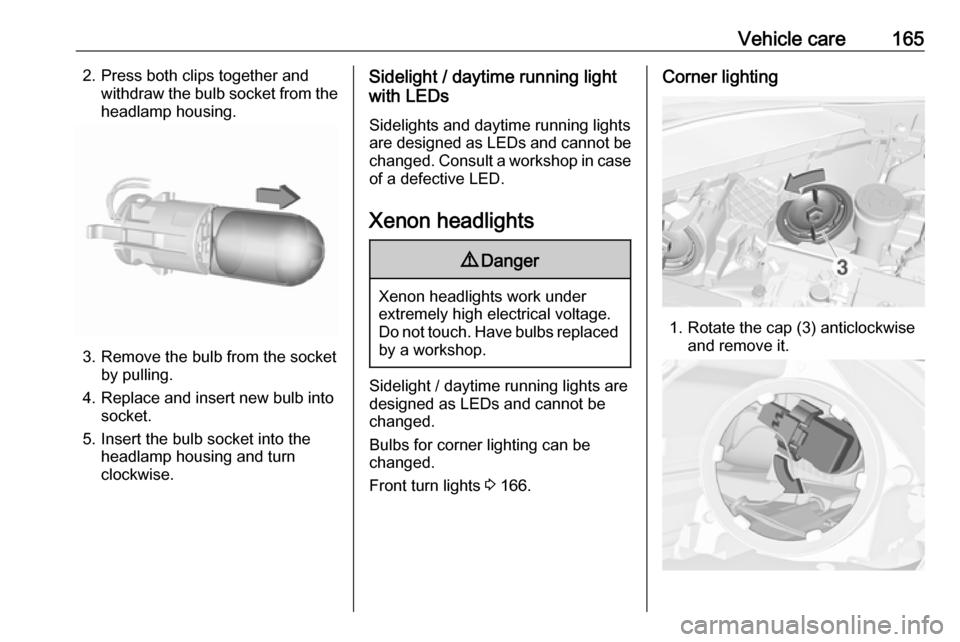
Vehicle care1652. Press both clips together andwithdraw the bulb socket from theheadlamp housing.
3. Remove the bulb from the socket by pulling.
4. Replace and insert new bulb into socket.
5. Insert the bulb socket into the headlamp housing and turn
clockwise.
Sidelight / daytime running light
with LEDs
Sidelights and daytime running lights
are designed as LEDs and cannot be
changed. Consult a workshop in case
of a defective LED.
Xenon headlights9 Danger
Xenon headlights work under
extremely high electrical voltage.
Do not touch. Have bulbs replaced by a workshop.
Sidelight / daytime running lights are
designed as LEDs and cannot be
changed.
Bulbs for corner lighting can be
changed.
Front turn lights 3 166.
Corner lighting
1. Rotate the cap (3) anticlockwise
and remove it.
Page 168 of 229

166Vehicle care2. Rotate the bulb holderanticlockwise to disengage.
Withdraw the bulb holder from the
reflector.
3. Remove the bulb from the plug connector by disengaging and
pulling.
4. Replace the bulb. Connect and engage bulb holder with the plug
connector.
5. Insert the bulb holder into the reflector and rotate clockwise to
secure.
6. Fit the cap and rotate clockwise.
Front fog lights
The bulbs are accessible from the
underside of the vehicle.
1. Turn the bulb holder anti- clockwise and remove it from the
reflector.
2. Disengage the bulb socket from the plug connector by pressing
the retaining lug.
3. Remove and replace the bulb socket with bulb and attach the
plug connector.
4. Insert the bulb socket into the reflector by turning clockwise and
engage.
Front turn lights Front turn lights consist of long-life
bulbs which cannot be changed.
Consult a workshop in case of a
defective long-life bulb.
Page 170 of 229

168Vehicle care5. Remove the bulb by pushing thebulb slightly into the socket and
rotating anticlockwise:
Tail light / brake light ( 1)
Turn light ( 2)
6. Insert bulb into bulb carrier and turn clockwise. Engage bulbcarrier into the light assembly. Fit
light assembly with the retaining
pins into the recesses of the
vehicle body and tighten the
plastic securing nuts from inside
the load compartment.
Close cover and engage.
Reversing light / rear fog light Reversing light is located on the leftlight assembly in the tailgate, and the
rear fog light is located on the right
light assembly in the tailgate.
The description of bulb replacement
is the same for both lights.
1. Remove screw from the tailgate.
2. Move light assembly slightly to the
outside, then withdraw from the
tailgate.
3. Remove the bulb holder by turning.
Page 171 of 229

Vehicle care1694. Remove the bulb by pushingslightly into the socket and
rotating anticlockwise. Replace
the bulb.
5. Insert the bulb socket into the assembly and turn to secure.
6. Attach light assembly into the tailgate and secure with the
screw.
Side turn lights To replace bulb, remove lamp
housing:
1. Slide lamp to its left side and remove with its right end.
2. Turn bulb holder anticlockwiseand remove from housing.
3. Pull bulb from bulb holder and replace it.
4. Insert bulb holder and turnclockwise.
5. Insert left end of the lamp, slide to
the left and insert right end.
Centre high-mounted brake light
Have LEDs replaced by a workshop.
Number plate light
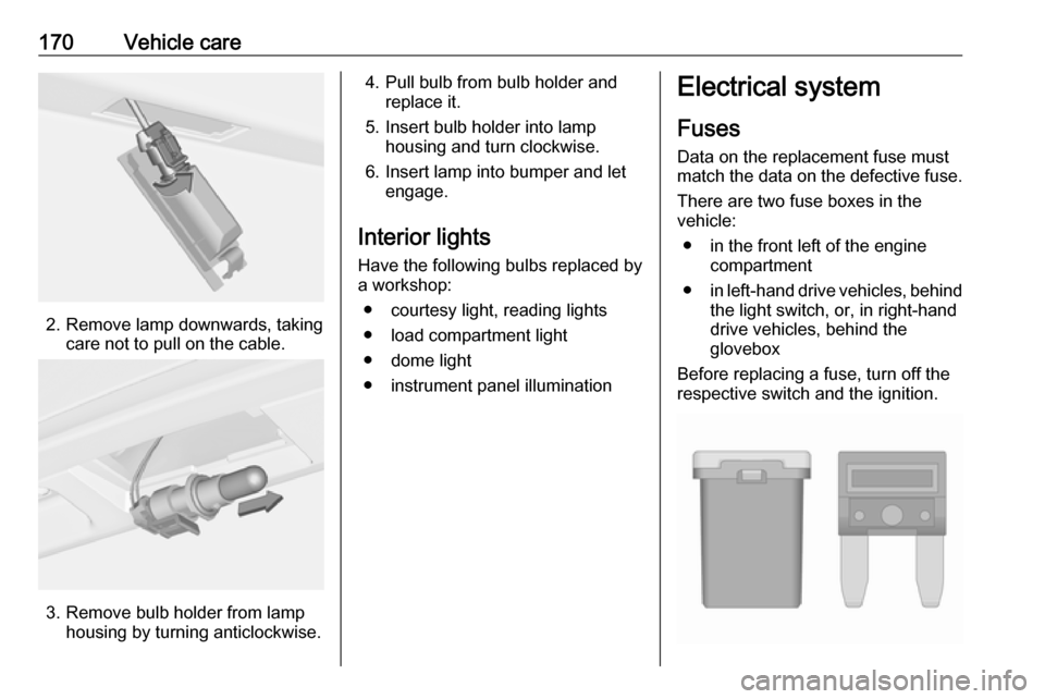
1. Insert screwdriver in recess of the
cover, press to the side and
release spring.
Page 172 of 229

170Vehicle care
2. Remove lamp downwards, takingcare not to pull on the cable.
3. Remove bulb holder from lamphousing by turning anticlockwise.
4. Pull bulb from bulb holder andreplace it.
5. Insert bulb holder into lamp housing and turn clockwise.
6. Insert lamp into bumper and let engage.
Interior lights
Have the following bulbs replaced by
a workshop:
● courtesy light, reading lights
● load compartment light
● dome light
● instrument panel illuminationElectrical system
Fuses Data on the replacement fuse must
match the data on the defective fuse.
There are two fuse boxes in the
vehicle:
● in the front left of the engine compartment
● in left-hand drive vehicles, behind
the light switch, or, in right-hand
drive vehicles, behind the
glovebox
Before replacing a fuse, turn off the respective switch and the ignition.
Page 185 of 229

Vehicle care183Tyres age, even if they are not used.
We recommend tyre replacement
every six years.
Changing tyre and wheel
size
If tyres of a different size than thosefitted at the factory are used, it may be
necessary to reprogramme the
nominal tyre pressure and to make
other vehicle modifications.
After converting to a different tyre
size, have the label with tyre
pressures replaced.
Tyre pressure monitoring system
3 178.Caution
When converting to wheels with
14 inch diameter, the ground
clearance will be reduced. This
must be considered when passing
over obstacles.
9 Warning
The use of unsuitable tyres or
wheels may lead to accidents and will invalidate the vehicle
operating permit.
Wheel covers
Wheel covers and tyres that are
factory approved for the respective
vehicle and comply with all of the
relevant wheel and tyre combination
requirements must be used.
If the wheel covers and tyres used are
not factory approved, the tyres must
not have a rim protection ridge.
Wheel covers must not impair brake
cooling.
9 Warning
Use of unsuitable tyres or wheel
covers could lead to sudden
pressure loss and thereby
accidents.
Steel wheels: When using locking
wheel nuts don't attach wheel covers.
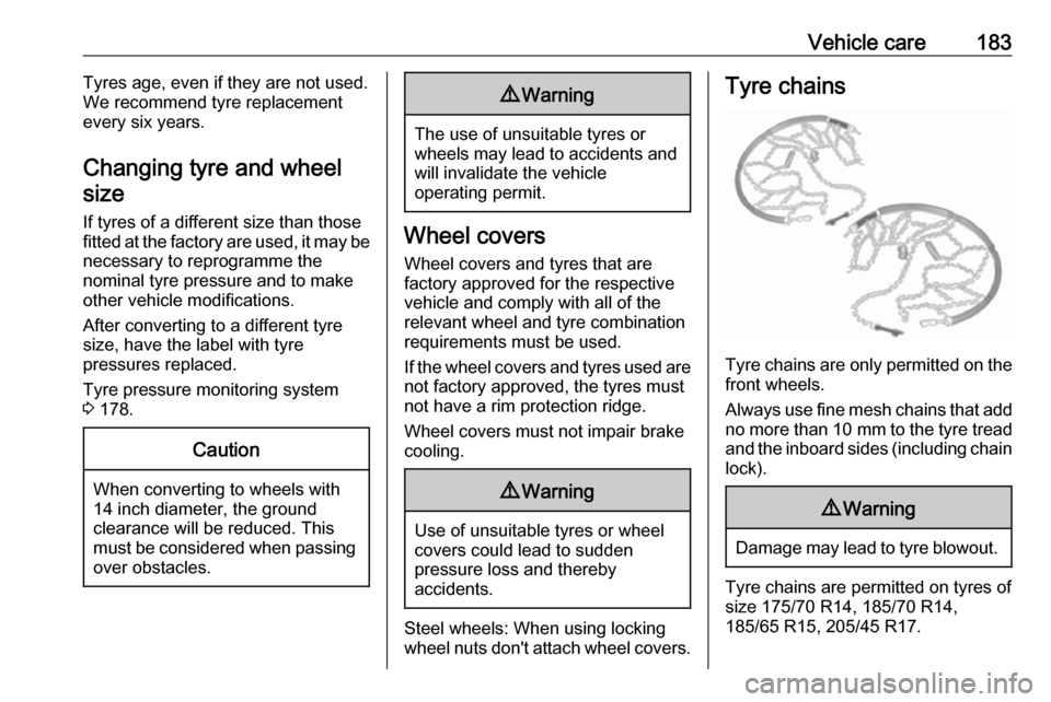
Tyre chains
Tyre chains are only permitted on the
front wheels.
Always use fine mesh chains that add no more than 10 mm to the tyre tread
and the inboard sides (including chain lock).
9 Warning
Damage may lead to tyre blowout.
Tyre chains are permitted on tyres of
size 175/70 R14, 185/70 R14,
185/65 R15, 205/45 R17.
Page 193 of 229

Vehicle care191●If the ground on which the vehicle
is standing is soft, a solid board
(max. 1 cm thick) should be
placed under the jack.
● Take heavy objects out of the vehicle before jacking up.
● No people or animals may be in the vehicle when it is jacked-up.
● Never crawl under a jacked-up vehicle.
● Do not start the vehicle when it is
raised on the jack.
● Before screwing in the wheel bolts, clean them and lightly coat
the taper of each wheel bolt with
commercially available grease.9 Warning
Do not grease the thread of the
wheel bolt.
1. Steel wheels:
Pull off the wheel cover.
Alloy wheels with bolt caps Disengage wheel bolt caps with a
screwdriver and remove. To
protect the wheel, place a soft
cloth between the screwdriver
and the alloy wheel.
2. Install the wheel wrench ensuring that it locates securely and loosen
each wheel bolt by half a turn.
The wheels might be protected by
locking wheel bolts. To loosen
these specific bolts, first attach
the adapter for the locking wheel
bolts onto the head of the bolt
before installing the wheel
wrench. The adapter is located in
the glovebox.
3. Ensure the jack is correctly positioned under the relevant
vehicle jacking point.
On versions with sill panels or
retrofitted sill panels, no jack may
be used. The vehicle may be
damaged.
Page 194 of 229

192Vehicle care
4. Set the jack to the necessaryheight. Position it directly below
the jacking point in a manner that
prevents it from slipping.
Attach jack handle and with the
jack correctly aligned rotate handle until wheel is clear of theground.
5. Unscrew the wheel bolts.
6. Change the wheel.
7. Screw on the wheel bolts.
8. Lower vehicle.
9. Install the wheel wrench ensuring that it is securely located and
tighten each bolt in a crosswise
sequence. Tightening torque is
110 Nm.
10. Align the valve hole in the wheel cover of the steel wheel with the
tyre valve before installing.
Install wheel bolt caps or centre
cap on alloy wheel.
11. Install vehicle jacking point cover.
12. Stow and secure the replaced wheel and the vehicle tools
3 175.
Stow the adapter for the locking
wheel bolts 3 53.
13. Check the tyre pressure of the installed tyre and the wheel bolt
torque as soon as possible.Spare wheel with directional tyre
If possible, fit directional tyres such
that they roll in the direction of travel.
The rolling direction is indicated by a
symbol (e.g. an arrow) on the
sidewall.
The following applies to tyres fitted
opposing the rolling direction:
● Driveability may be affected. Have the defective tyre renewed
or repaired as soon as possible
and fit it instead of the spare
wheel.
● Drive particularly carefully on wet
and snow-covered road
surfaces.
Page 196 of 229

194Vehicle care3. Connect the black lead to thenegative terminal of the booster
vehicle battery.
4. Connect the other end of the black
lead to a vehicle grounding point,
such as the engine block or an
engine mounting bolt. Connect as far away from the discharged
vehicle battery as possible,
however at least 60 cm.
Route the leads so that they cannot
catch on rotating parts in the engine
compartment.
To start the engine: 1. Start the engine of the vehicle providing the jump.
2. After 5 minutes, start the other engine. Start attempts should be
made for no longer than
15 seconds at an interval of 1 minute.
3. Allow both engines to idle for approx. 3 minutes with the leads
connected.4. Switch on electrical consumers (e.g. headlights, heated rear
window) of the vehicle receiving
the jump start.
5. Reverse above sequence exactly when removing leads.Towing
Towing the vehicle
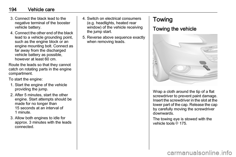
Wrap a cloth around the tip of a flat
screwdriver to prevent paint damage.
Insert the screwdriver in the slot at the
lower part of the cap. Release the cap by carefully moving the screwdriver
downwards.
The towing eye is stowed with the
vehicle tools 3 175.