engine VAUXHALL CORSA F 2019 Repair Manual
[x] Cancel search | Manufacturer: VAUXHALL, Model Year: 2019, Model line: CORSA F, Model: VAUXHALL CORSA F 2019Pages: 229, PDF Size: 6.72 MB
Page 161 of 229
Vehicle care159
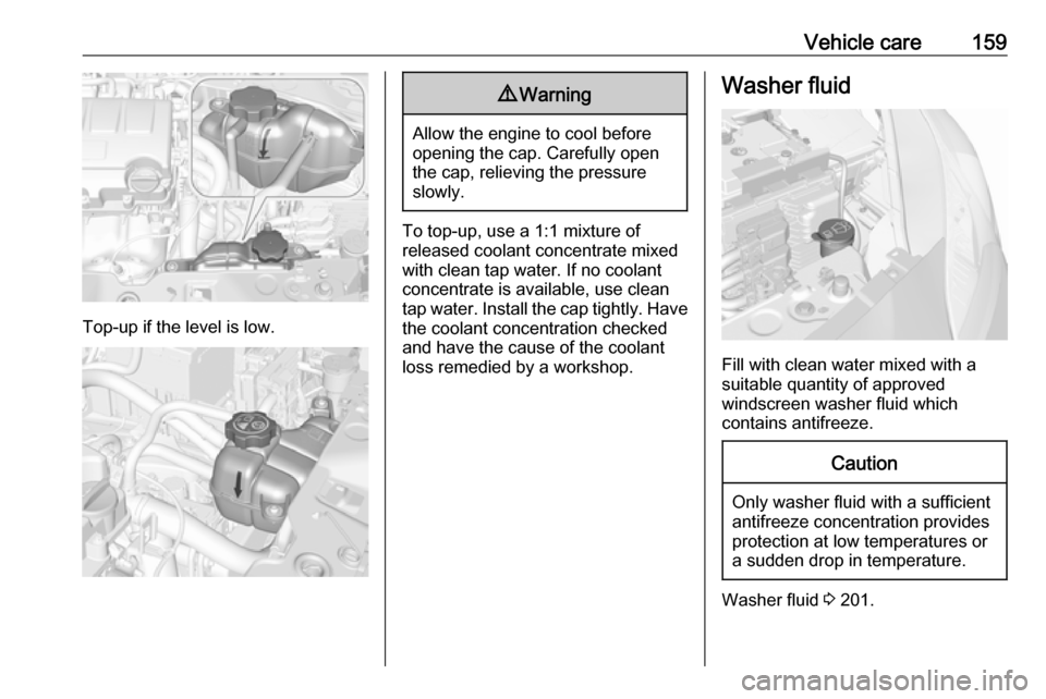
Top-up if the level is low.
9Warning
Allow the engine to cool before
opening the cap. Carefully open
the cap, relieving the pressure
slowly.
To top-up, use a 1:1 mixture of released coolant concentrate mixed
with clean tap water. If no coolant
concentrate is available, use clean
tap water. Install the cap tightly. Have
the coolant concentration checked
and have the cause of the coolant
loss remedied by a workshop.
Washer fluid
Fill with clean water mixed with a
suitable quantity of approved
windscreen washer fluid which
contains antifreeze.
Caution
Only washer fluid with a sufficient
antifreeze concentration provides
protection at low temperatures or
a sudden drop in temperature.
Washer fluid 3 201.
Page 162 of 229
160Vehicle careBrakesIn the event of minimum thickness of
the brake lining, a squealing noise
sounds during braking.
Continued driving is possible but
have the brake lining replaced as
soon as possible.
Once new brake linings are installed,
do not brake unnecessarily hard for
the first few journeys.
Brake fluid9 Warning
Brake fluid is poisonous and
corrosive. Avoid contact with eyes, skin, fabrics and painted surfaces.
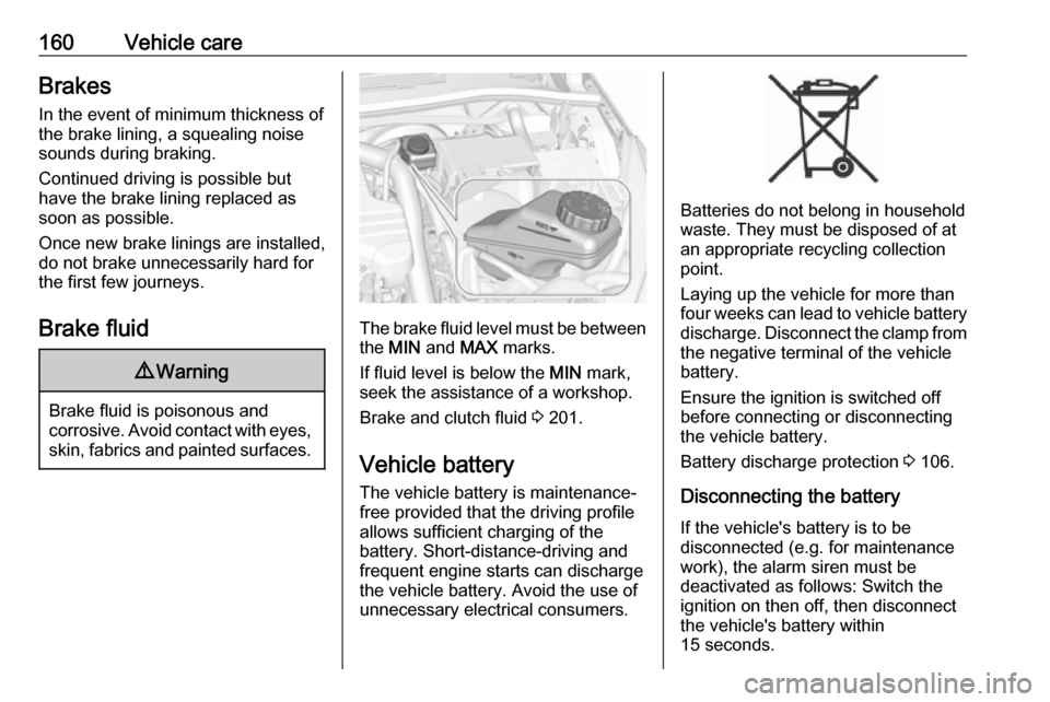
The brake fluid level must be betweenthe MIN and MAX marks.
If fluid level is below the MIN mark,
seek the assistance of a workshop.
Brake and clutch fluid 3 201.
Vehicle battery
The vehicle battery is maintenance-
free provided that the driving profile
allows sufficient charging of the
battery. Short-distance-driving and
frequent engine starts can discharge
the vehicle battery. Avoid the use of
unnecessary electrical consumers.
Batteries do not belong in household
waste. They must be disposed of at
an appropriate recycling collection
point.
Laying up the vehicle for more than
four weeks can lead to vehicle battery
discharge. Disconnect the clamp from
the negative terminal of the vehicle
battery.
Ensure the ignition is switched off
before connecting or disconnecting
the vehicle battery.
Battery discharge protection 3 106.
Disconnecting the battery If the vehicle's battery is to be
disconnected (e.g. for maintenance
work), the alarm siren must be
deactivated as follows: Switch the
ignition on then off, then disconnect
the vehicle's battery within
15 seconds.
Page 164 of 229
162Vehicle careWiper blade replacementWindscreen
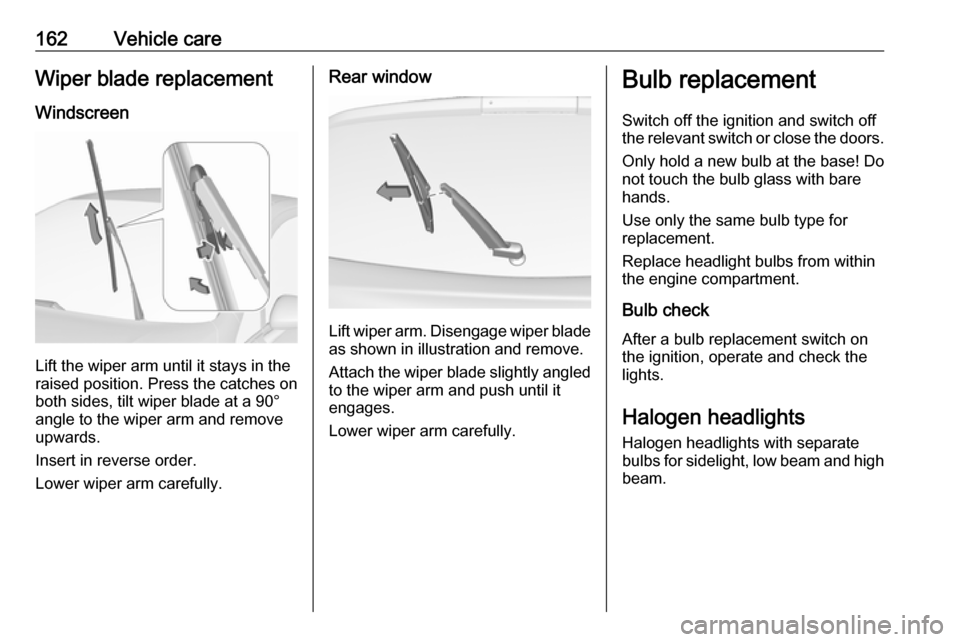
Lift the wiper arm until it stays in the
raised position. Press the catches on
both sides, tilt wiper blade at a 90°
angle to the wiper arm and remove
upwards.
Insert in reverse order.
Lower wiper arm carefully.
Rear window
Lift wiper arm. Disengage wiper blade as shown in illustration and remove.
Attach the wiper blade slightly angled
to the wiper arm and push until it
engages.
Lower wiper arm carefully.
Bulb replacement
Switch off the ignition and switch off
the relevant switch or close the doors.
Only hold a new bulb at the base! Do not touch the bulb glass with bare
hands.
Use only the same bulb type for
replacement.
Replace headlight bulbs from within
the engine compartment.
Bulb check
After a bulb replacement switch on
the ignition, operate and check the
lights.
Halogen headlights Halogen headlights with separate
bulbs for sidelight, low beam and high
beam.
Page 172 of 229
170Vehicle care
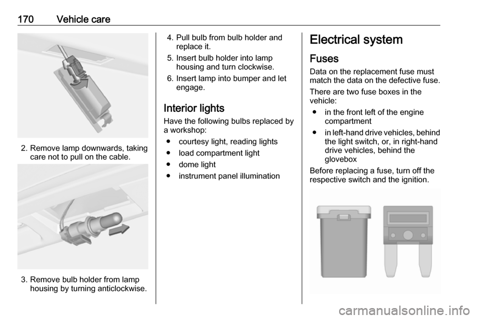
2. Remove lamp downwards, takingcare not to pull on the cable.
3. Remove bulb holder from lamphousing by turning anticlockwise.
4. Pull bulb from bulb holder andreplace it.
5. Insert bulb holder into lamp housing and turn clockwise.
6. Insert lamp into bumper and let engage.
Interior lights
Have the following bulbs replaced by
a workshop:
● courtesy light, reading lights
● load compartment light
● dome light
● instrument panel illuminationElectrical system
Fuses Data on the replacement fuse must
match the data on the defective fuse.
There are two fuse boxes in the
vehicle:
● in the front left of the engine compartment
● in left-hand drive vehicles, behind
the light switch, or, in right-hand
drive vehicles, behind the
glovebox
Before replacing a fuse, turn off the respective switch and the ignition.
Page 173 of 229
Vehicle care171There are different kinds of fuses in
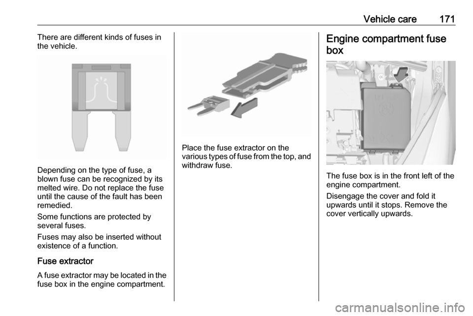
the vehicle.
Depending on the type of fuse, a
blown fuse can be recognized by its
melted wire. Do not replace the fuse until the cause of the fault has been
remedied.
Some functions are protected by
several fuses.
Fuses may also be inserted without existence of a function.
Fuse extractorA fuse extractor may be located in the
fuse box in the engine compartment.
Place the fuse extractor on the
various types of fuse from the top, and withdraw fuse.
Engine compartment fuse
box
The fuse box is in the front left of the
engine compartment.
Disengage the cover and fold it
upwards until it stops. Remove the
cover vertically upwards.
Page 174 of 229
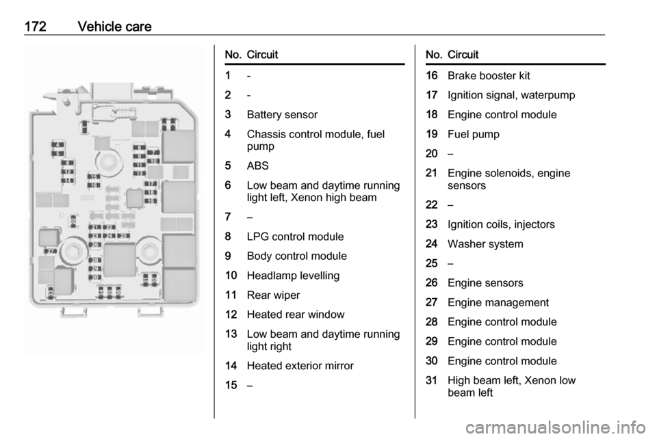
172Vehicle careNo.Circuit1-2-3Battery sensor4Chassis control module, fuel
pump5ABS6Low beam and daytime running
light left, Xenon high beam7–8LPG control module9Body control module10Headlamp levelling11Rear wiper12Heated rear window13Low beam and daytime running
light right14Heated exterior mirror15–No.Circuit16Brake booster kit17Ignition signal, waterpump18Engine control module19Fuel pump20–21Engine solenoids, engine
sensors22–23Ignition coils, injectors24Washer system25–26Engine sensors27Engine management28Engine control module29Engine control module30Engine control module31High beam left, Xenon low
beam left
Page 175 of 229
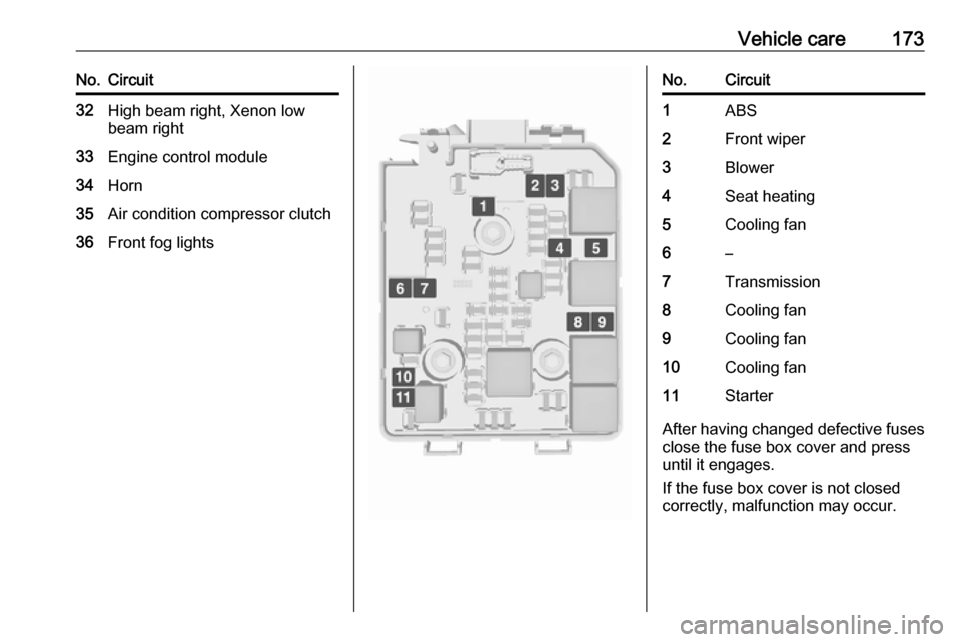
Vehicle care173No.Circuit32High beam right, Xenon low
beam right33Engine control module34Horn35Air condition compressor clutch36Front fog lightsNo.Circuit1ABS2Front wiper3Blower4Seat heating5Cooling fan6–7Transmission8Cooling fan9Cooling fan10Cooling fan11Starter
After having changed defective fuses
close the fuse box cover and press
until it engages.
If the fuse box cover is not closed
correctly, malfunction may occur.
Page 180 of 229
178Vehicle careTyre pressures differ depending onvarious options.
For the correct tyre pressure value,
follow the procedure below:
● Identify the engine identifier code. Engine data 3 208.
● Identify the respective tyre.
The tyre pressure table indicates the
required pressure for a specific tyre
size only 3 212.
For the tyres approved for your
vehicle, refer to the EEC Certificate of Conformity provided with your vehicle
or other national registration
documents.
The driver is responsible for correct
adjustment of tyre pressure.9 Warning
If the pressure is too low, this can
result in considerable tyre warm-
up and internal damage, leading to tread separation and even to tyre
blow-out at high speeds.
9 Warning
For specific tyres the
recommended tyre pressure as
shown in the tyre pressure table may exceed the maximum tyre
pressure as indicated on the tyre.
Never exceed the maximum tyre
pressure as indicated on the tyre.
If the tyre pressure must be reduced
or increased, switch off ignition. After
adjusting tyre pressure switch on
ignition and select the relevant setting on the page Tyre load in the Driver
Information Centre 3 81.
Temperature dependency
The tyre pressure depends on the
temperature of the tyre. During
driving, tyre temperature and
pressure increase. Tyre pressure
values provided on the tyre
information label and tyre pressure
chart are valid for cold tyres, which
means at 20 °C.
The pressure increases by nearly
1.5 psi for a 10 °C temperature
increase. This must be considered
when warm tyres are checked.
The tyre pressure value displayed in
the Driver Information Centre shows
the real tyre pressure. A cooled down tyre will show a decreased value,
which does not indicate an air leak.
Tyre pressure monitoringsystem
The tyre pressure monitoring system
checks the pressure of all four tyres
once a minute when vehicle speed
exceeds a certain limit.Caution
Tyre pressure monitoring system
warns only about low tyre pressure condition and does not replace
regular tyre maintenance by the
driver.
All wheels must be equipped with pressure sensors and the tyres must
have the prescribed pressure.
Page 187 of 229
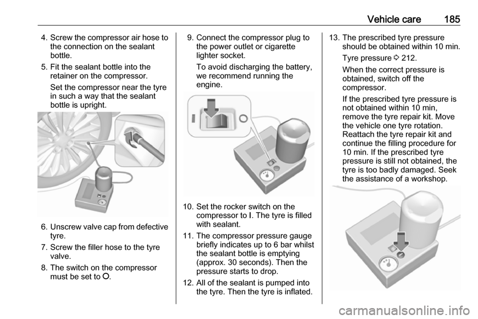
Vehicle care1854.Screw the compressor air hose to
the connection on the sealant
bottle.
5. Fit the sealant bottle into the retainer on the compressor.
Set the compressor near the tyre
in such a way that the sealant
bottle is upright.
6. Unscrew valve cap from defective
tyre.
7. Screw the filler hose to the tyre valve.
8. The switch on the compressor must be set to J.
9. Connect the compressor plug to
the power outlet or cigarette
lighter socket.
To avoid discharging the battery,
we recommend running the
engine.
10. Set the rocker switch on the compressor to I. The tyre is filled
with sealant.
11. The compressor pressure gauge briefly indicates up to 6 bar whilstthe sealant bottle is emptying
(approx. 30 seconds). Then the
pressure starts to drop.
12. All of the sealant is pumped into the tyre. Then the tyre is inflated.
13. The prescribed tyre pressure should be obtained within 10 min.
Tyre pressure 3 212.
When the correct pressure is
obtained, switch off the
compressor.
If the prescribed tyre pressure is
not obtained within 10 min,
remove the tyre repair kit. Move
the vehicle one tyre rotation.
Reattach the tyre repair kit and
continue the filling procedure for
10 min. If the prescribed tyre
pressure is still not obtained, the
tyre is too badly damaged. Seek
the assistance of a workshop.
Page 189 of 229

Vehicle care187
1. Take the sealant bottle andbracket with air hose from the
insert.
2. Detach air hose from bracket and screw onto sealant bottle
connection.
3. Position the sealant bottle on the bracket. Make sure that the bottle
does not fall.
4. Unscrew valve cap from defective
tyre.
5. Screw tyre inflation hose to valve.
6. Screw air hose onto compressor connection.
7. Switch on ignition. To avoid discharging the battery,
we recommend running the
engine.