ECO VAUXHALL CORSA F 2020 User Guide
[x] Cancel search | Manufacturer: VAUXHALL, Model Year: 2020, Model line: CORSA F, Model: VAUXHALL CORSA F 2020Pages: 227, PDF Size: 18.77 MB
Page 32 of 227
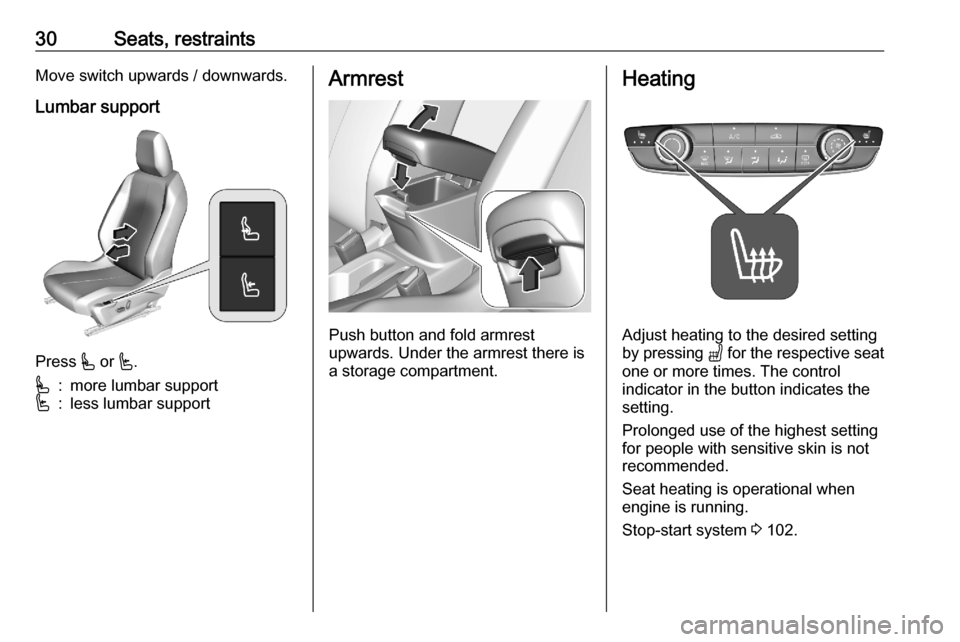
30Seats, restraintsMove switch upwards / downwards.Lumbar support
Press * or '.
*:more lumbar support':less lumbar supportArmrest
Push button and fold armrest
upwards. Under the armrest there is
a storage compartment.
Heating
Adjust heating to the desired setting
by pressing " for the respective seat
one or more times. The control
indicator in the button indicates the
setting.
Prolonged use of the highest setting
for people with sensitive skin is not
recommended.
Seat heating is operational when engine is running.
Stop-start system 3 102.
Page 35 of 227
Seats, restraints33Unfasten
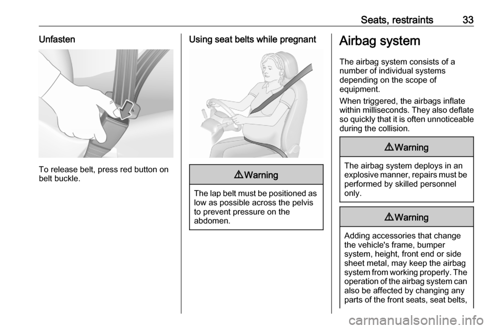
To release belt, press red button on
belt buckle.
Using seat belts while pregnant9 Warning
The lap belt must be positioned as
low as possible across the pelvis
to prevent pressure on the
abdomen.
Airbag system
The airbag system consists of a
number of individual systems
depending on the scope of
equipment.
When triggered, the airbags inflate
within milliseconds. They also deflate
so quickly that it is often unnoticeable
during the collision.9 Warning
The airbag system deploys in an
explosive manner, repairs must be performed by skilled personnel
only.
9 Warning
Adding accessories that change
the vehicle's frame, bumper
system, height, front end or side
sheet metal, may keep the airbag
system from working properly. The operation of the airbag system can
also be affected by changing any
parts of the front seats, seat belts,
Page 41 of 227
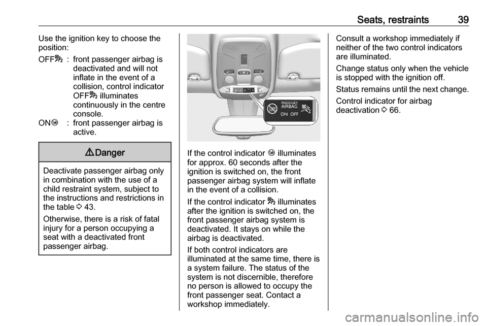
Seats, restraints39Use the ignition key to choose theposition:OFF *:front passenger airbag is
deactivated and will not
inflate in the event of a
collision, control indicator
OFF * illuminates
continuously in the centre
console.ON Ó:front passenger airbag is
active.9 Danger
Deactivate passenger airbag only
in combination with the use of a
child restraint system, subject to
the instructions and restrictions in
the table 3 43.
Otherwise, there is a risk of fatal
injury for a person occupying a
seat with a deactivated front
passenger airbag.
If the control indicator Ó illuminates
for approx. 60 seconds after the
ignition is switched on, the front
passenger airbag system will inflate
in the event of a collision.
If the control indicator * illuminates
after the ignition is switched on, the front passenger airbag system is
deactivated. It stays on while the
airbag is deactivated.
If both control indicators are
illuminated at the same time, there is
a system failure. The status of the
system is not discernible, therefore
no person is allowed to occupy the
front passenger seat. Contact a
workshop immediately.
Consult a workshop immediately if
neither of the two control indicators
are illuminated.
Change status only when the vehicle is stopped with the ignition off.
Status remains until the next change.
Control indicator for airbag
deactivation 3 66.
Page 42 of 227
40Seats, restraintsChild restraintsChild restraint systems9 Danger
If using a rear-facing child restraint
system on the front passenger
seat, the airbag system for the
front passenger seat must be
deactivated. This also applies to certain forward-facing child
restraint systems as indicated in
the tables 3 43.
Airbag deactivation 3 38.
Airbag label 3 33.
We recommend a child restraint system which is tailored specifically to the vehicle. For further information,
contact your workshop.
Before fastening a child seat adjust
the head restraint 3 26.
When a child restraint system is being
used, pay attention to the following
usage and installation instructions and also those supplied with the child restraint system.
Always comply with local or national
regulations. In some countries, the
use of child restraint systems is
forbidden on certain seats.
Child restraint systems can be
fastened with:
● Three-point seat belt
● ISOFIX brackets
● Top-tether
Three-point seat belt
Child restraint systems can be
fastened by using a three-point seat
belt. After fastening the child restraint system the seat belt has to be
tightened 3 43.ISOFIX brackets
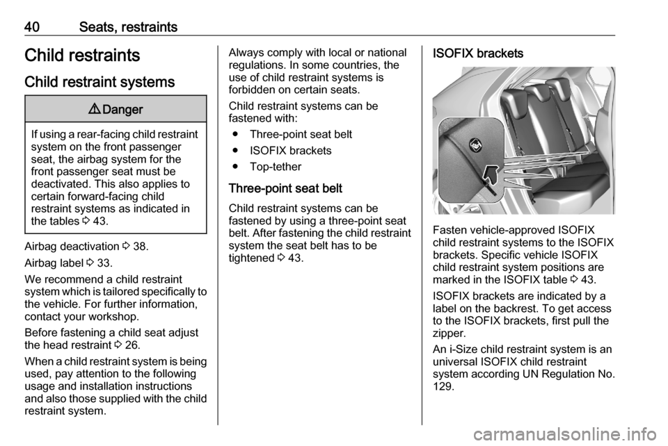
Fasten vehicle-approved ISOFIX
child restraint systems to the ISOFIX
brackets. Specific vehicle ISOFIX
child restraint system positions are
marked in the ISOFIX table 3 43.
ISOFIX brackets are indicated by a
label on the backrest. To get access
to the ISOFIX brackets, first pull the
zipper.
An i-Size child restraint system is an
universal ISOFIX child restraint
system according UN Regulation No.
129.
Page 43 of 227
Seats, restraints41All i-Size child restraint systems can
be used on any vehicle seat suitable
for i-Size, i-Size table 3 43.
Either a Top-tether strap or a support
leg must be used in addition to the
ISOFIX brackets.
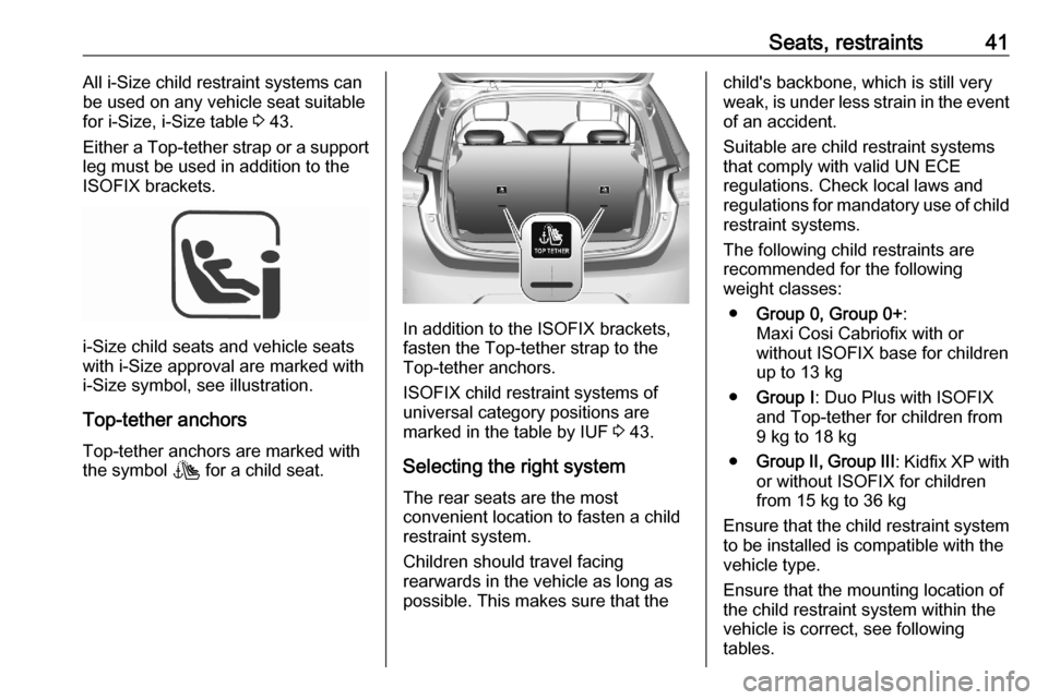
i-Size child seats and vehicle seats
with i-Size approval are marked with i-Size symbol, see illustration.
Top-tether anchors
Top-tether anchors are marked with
the symbol t for a child seat.In addition to the ISOFIX brackets,
fasten the Top-tether strap to the
Top-tether anchors.
ISOFIX child restraint systems of
universal category positions are
marked in the table by IUF 3 43.
Selecting the right system
The rear seats are the most
convenient location to fasten a child
restraint system.
Children should travel facing
rearwards in the vehicle as long as
possible. This makes sure that the
child's backbone, which is still very
weak, is under less strain in the event of an accident.
Suitable are child restraint systems
that comply with valid UN ECE
regulations. Check local laws and
regulations for mandatory use of child restraint systems.
The following child restraints are
recommended for the following
weight classes:
● Group 0, Group 0+ :
Maxi Cosi Cabriofix with or
without ISOFIX base for children
up to 13 kg
● Group I : Duo Plus with ISOFIX
and Top-tether for children from 9 kg to 18 kg
● Group II, Group III : Kidfix XP with
or without ISOFIX for children
from 15 kg to 36 kg
Ensure that the child restraint system
to be installed is compatible with the
vehicle type.
Ensure that the mounting location of
the child restraint system within the
vehicle is correct, see following
tables.
Page 52 of 227
50StorageRemove the cover.
Fitting cover Engage cover in side guides and fold
downwards. Attach the retaining
straps to the tailgate.
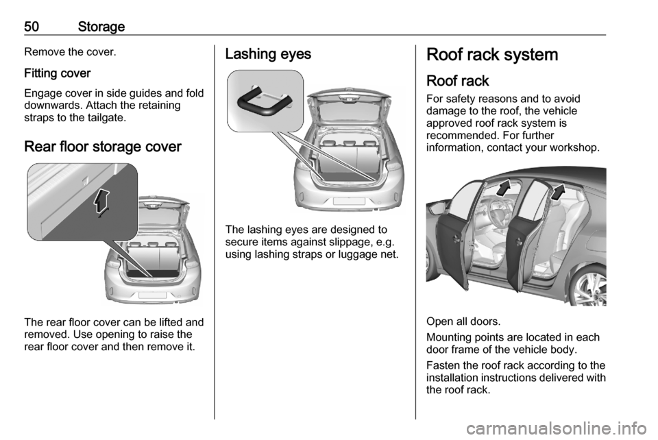
Rear floor storage cover
The rear floor cover can be lifted and
removed. Use opening to raise the
rear floor cover and then remove it.
Lashing eyes
The lashing eyes are designed to
secure items against slippage, e.g.
using lashing straps or luggage net.
Roof rack system
Roof rack For safety reasons and to avoid
damage to the roof, the vehicle
approved roof rack system is
recommended. For further
information, contact your workshop.
Open all doors.
Mounting points are located in each
door frame of the vehicle body.
Fasten the roof rack according to the installation instructions delivered with the roof rack.
Page 57 of 227
Instruments and controls55The recommended grip areas of the
steering wheel are heated quicker
and to a higher temperature than the
other areas.
Heating is operational when the
engine is running and during an
Autostop.
Stop-start system 3 102.
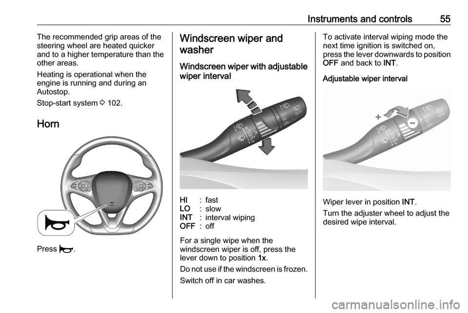
Horn
Press d.
Windscreen wiper and
washer
Windscreen wiper with adjustablewiper intervalHI:fastLO:slowINT:interval wipingOFF:off
For a single wipe when the
windscreen wiper is off, press the
lever down to position 1x.
Do not use if the windscreen is frozen.
Switch off in car washes.
To activate interval wiping mode the
next time ignition is switched on,
press the lever downwards to position
OFF and back to INT.
Adjustable wiper interval
Wiper lever in position INT.
Turn the adjuster wheel to adjust the
desired wipe interval.
Page 61 of 227
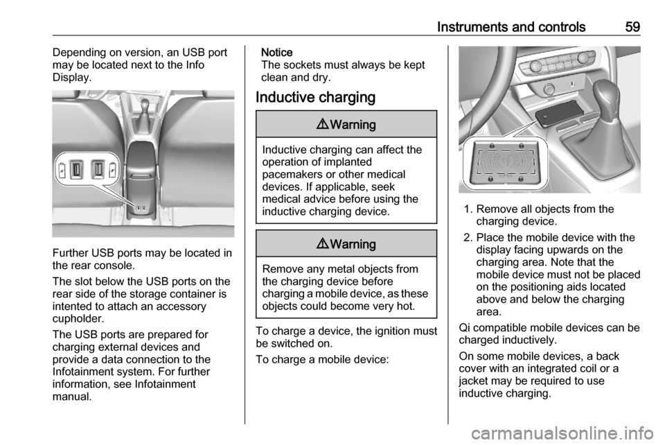
Instruments and controls59Depending on version, an USB port
may be located next to the Info
Display.
Further USB ports may be located in
the rear console.
The slot below the USB ports on the rear side of the storage container is
intented to attach an accessory
cupholder.
The USB ports are prepared for
charging external devices and
provide a data connection to the
Infotainment system. For further
information, see Infotainment
manual.
Notice
The sockets must always be kept
clean and dry.
Inductive charging9 Warning
Inductive charging can affect the
operation of implanted
pacemakers or other medical
devices. If applicable, seek
medical advice before using the
inductive charging device.
9 Warning
Remove any metal objects from
the charging device before
charging a mobile device, as these objects could become very hot.
To charge a device, the ignition must
be switched on.
To charge a mobile device:
1. Remove all objects from the charging device.
2. Place the mobile device with the display facing upwards on the
charging area. Note that the
mobile device must not be placed
on the positioning aids located
above and below the charging
area.
Qi compatible mobile devices can be
charged inductively.
On some mobile devices, a back
cover with an integrated coil or a
jacket may be required to use
inductive charging.
Page 64 of 227
62Instruments and controlsmActive emergency braking
3 72PDoor open 3 72
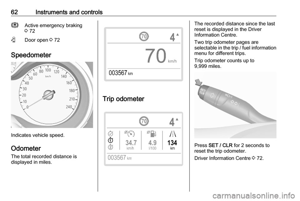
Speedometer
Indicates vehicle speed.
Odometer
The total recorded distance is
displayed in miles.
Trip odometer
The recorded distance since the last
reset is displayed in the Driver
Information Centre.
Two trip odometer pages are
selectable in the trip / fuel information menu for different trips.
Trip odometer counts up to
9,999 miles.
Press SET / CLR for 2 seconds to
reset the trip odometer.
Driver Information Centre 3 72.
Page 66 of 227

64Instruments and controlsCaution
If engine coolant temperature is
too high, stop vehicle, switch off
engine. Danger to engine. Check
coolant level.
Engine oil level monitor
The state of the engine oil level is
displayed in the Driver Information
Centre for a few seconds following
the service information after switching
on the ignition.
A proper state of engine oil level is
indicated by a message.
If oil level is low, T flashes and a
message is indicated, accompanied
by the C indicator. Confirm engine
oil level by using the dipstick and top
up engine oil respectively.
Engine oil 3 163.
A fault of measurement is indicated
by a message. Check engine oil level
manually by using the dipstick.
Service display
The service system informs when to
change the engine oil and filter or a
vehicle service is required. Based on
driving conditions, the interval at
which an engine oil and filter change
is required can vary considerably.
Service information 3 196.
A required service due is displayed in
the Driver Information Centre for several seconds after switching on
the ignition.
If no service is required for the next
1800 miles or more, no service
information appears in the display.
If service is required within the next
1800 miles, the remaining distance to
the next service due, the distance
travelled since the last service due or the time period that remains to the
next service due is indicated for
several seconds. Simultaneously
symbol C illuminates temporary as
reminder.
If service is required in less than
600 miles, the remaining distance to
the next service due, the distance
travelled since the last service due orthe time period that remains to the
next service due is indicated for
several seconds. Simultaneously
C illuminates permanently as
reminder.
Overdued service is indicated by a
message in the Driver Information
Centre which indicates the overdued
distance. C flashes and then
illuminates permanently until service
is executed.
Reset of service interval
After each service, the service
indicator must be reset to ensure
proper functionality. It is
recommended to seek the assistance of a workshop.
If service is executed by yourself,
operate as following:
● switch off ignition