ECU VAUXHALL CORSA F 2020 User Guide
[x] Cancel search | Manufacturer: VAUXHALL, Model Year: 2020, Model line: CORSA F, Model: VAUXHALL CORSA F 2020Pages: 227, PDF Size: 18.77 MB
Page 54 of 227

52StorageTo calculate the payload, enter
the data for your vehicle in the
weights table at the front of this
manual.
The EC kerb weight includes
weights for the driver (68 kg),
luggage (7 kg) and all fluids (fuel
tank 90% full).
Optional equipment and
accessories increase the kerb
weight.
● Driving with a roof load increases
the sensitivity of the vehicle to
cross-winds and has a
detrimental effect on vehicle
handling due to the vehicle's
higher centre of gravity.
Distribute the load evenly and
secure it properly with retaining
straps. Adjust the tyre pressure
and vehicle speed according to
the load conditions. Check and
retighten the straps frequently.
Do not drive faster than 75 mph.
The permissible roof load is
70 kg. Do not exceed a loading
height of 40 cm. The roof load is the combined weight of the roof
rack and the load.
Page 66 of 227

64Instruments and controlsCaution
If engine coolant temperature is
too high, stop vehicle, switch off
engine. Danger to engine. Check
coolant level.
Engine oil level monitor
The state of the engine oil level is
displayed in the Driver Information
Centre for a few seconds following
the service information after switching
on the ignition.
A proper state of engine oil level is
indicated by a message.
If oil level is low, T flashes and a
message is indicated, accompanied
by the C indicator. Confirm engine
oil level by using the dipstick and top
up engine oil respectively.
Engine oil 3 163.
A fault of measurement is indicated
by a message. Check engine oil level
manually by using the dipstick.
Service display
The service system informs when to
change the engine oil and filter or a
vehicle service is required. Based on
driving conditions, the interval at
which an engine oil and filter change
is required can vary considerably.
Service information 3 196.
A required service due is displayed in
the Driver Information Centre for several seconds after switching on
the ignition.
If no service is required for the next
1800 miles or more, no service
information appears in the display.
If service is required within the next
1800 miles, the remaining distance to
the next service due, the distance
travelled since the last service due or the time period that remains to the
next service due is indicated for
several seconds. Simultaneously
symbol C illuminates temporary as
reminder.
If service is required in less than
600 miles, the remaining distance to
the next service due, the distance
travelled since the last service due orthe time period that remains to the
next service due is indicated for
several seconds. Simultaneously
C illuminates permanently as
reminder.
Overdued service is indicated by a
message in the Driver Information
Centre which indicates the overdued
distance. C flashes and then
illuminates permanently until service
is executed.
Reset of service interval
After each service, the service
indicator must be reset to ensure
proper functionality. It is
recommended to seek the assistance of a workshop.
If service is executed by yourself,
operate as following:
● switch off ignition
Page 113 of 227
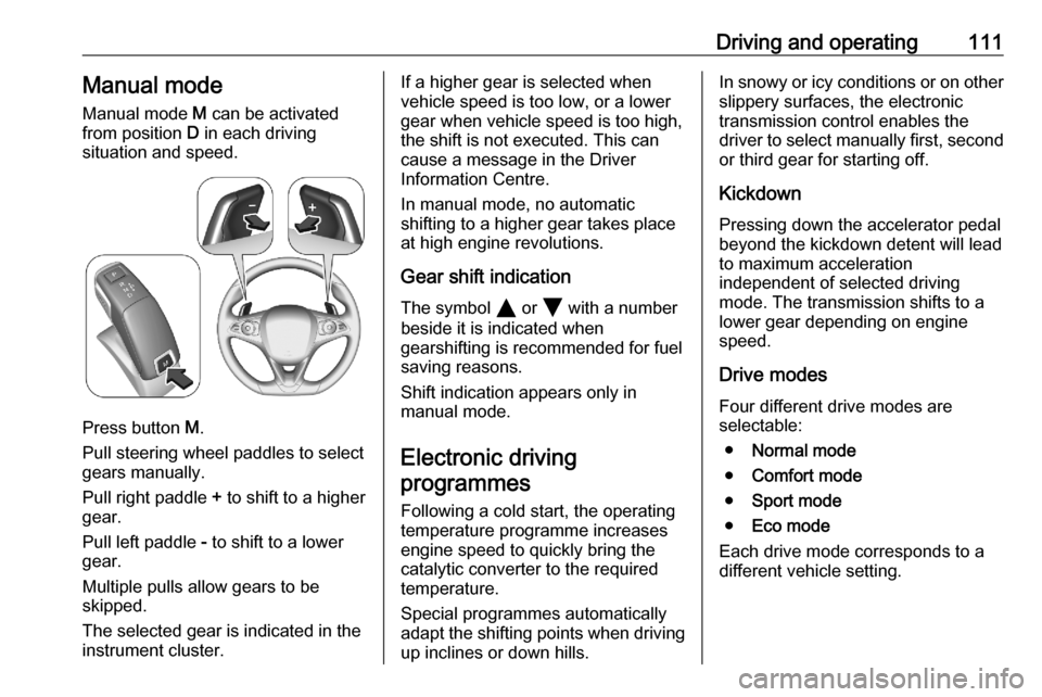
Driving and operating111Manual modeManual mode M can be activated
from position D in each driving
situation and speed.
Press button M.
Pull steering wheel paddles to select
gears manually.
Pull right paddle + to shift to a higher
gear.
Pull left paddle - to shift to a lower
gear.
Multiple pulls allow gears to be
skipped.
The selected gear is indicated in the
instrument cluster.
If a higher gear is selected when
vehicle speed is too low, or a lower
gear when vehicle speed is too high,
the shift is not executed. This can
cause a message in the Driver
Information Centre.
In manual mode, no automatic
shifting to a higher gear takes place
at high engine revolutions.
Gear shift indication
The symbol Y or Z with a number
beside it is indicated when
gearshifting is recommended for fuel
saving reasons.
Shift indication appears only in
manual mode.
Electronic driving programmes
Following a cold start, the operatingtemperature programme increasesengine speed to quickly bring the
catalytic converter to the required
temperature.
Special programmes automatically
adapt the shifting points when driving
up inclines or down hills.In snowy or icy conditions or on other
slippery surfaces, the electronic
transmission control enables the
driver to select manually first, second or third gear for starting off.
Kickdown
Pressing down the accelerator pedal
beyond the kickdown detent will lead to maximum acceleration
independent of selected driving
mode. The transmission shifts to a lower gear depending on engine
speed.
Drive modes Four different drive modes are
selectable:
● Normal mode
● Comfort mode
● Sport mode
● Eco mode
Each drive mode corresponds to a
different vehicle setting.
Page 164 of 227
162Vehicle careVehicle checks
Performing work9 Warning
Only perform engine compartment
checks when the ignition is off.
The cooling fan may start
operating even if the ignition is off.
9 Danger
The ignition system uses
extremely high voltage. Do not
touch.
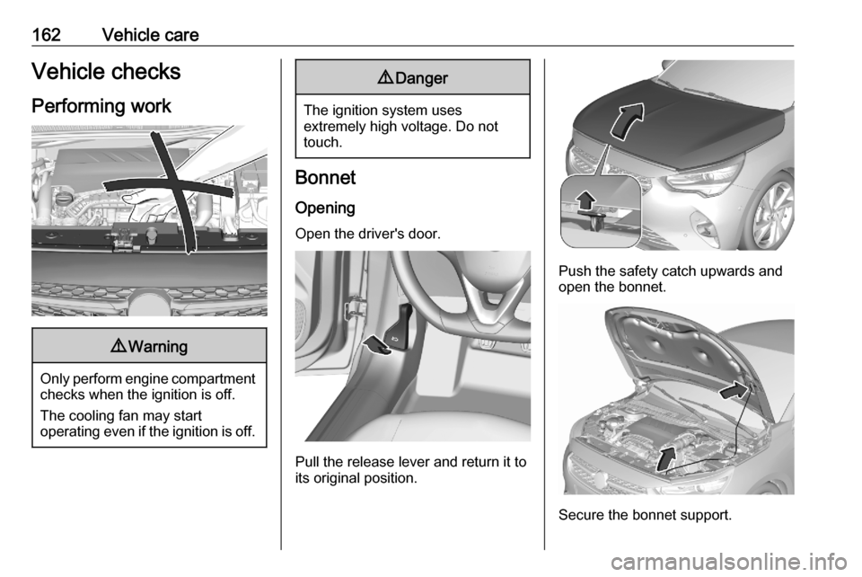
Bonnet
Opening
Open the driver's door.
Pull the release lever and return it to
its original position.
Push the safety catch upwards and
open the bonnet.
Secure the bonnet support.
Page 188 of 227
186Vehicle careFront arm position of the lifting
platform centrically under the relevant vehicle jacking point.
Spare wheel
The spare wheel can be classified as
a temporary spare wheel depending
on the size compared to the other
mounted wheels and country
regulations. In this case a permissible maximum speed applies, even
though no label at the spare wheel
indicates this.
Only mount one temporary spare
wheel. Do not drive faster than
50 mph. Take curves slowly. Do not
use for a long period of time.Caution
The use of a spare wheel that is smaller than the other wheels or in combination with winter tyres
could affect driveability. Have the defective tyre replaced as soon as
possible.
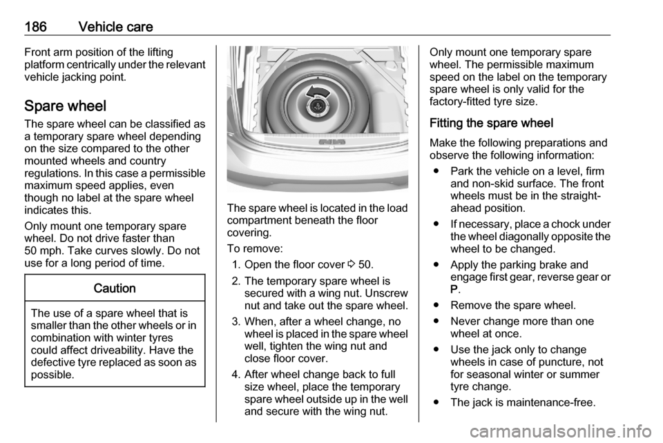
The spare wheel is located in the load
compartment beneath the floor
covering.
To remove: 1. Open the floor cover 3 50.
2. The temporary spare wheel is secured with a wing nut. Unscrew
nut and take out the spare wheel.
3. When, after a wheel change, no wheel is placed in the spare wheelwell, tighten the wing nut and
close floor cover.
4. After wheel change back to full size wheel, place the temporary
spare wheel outside up in the well
and secure with the wing nut.
Only mount one temporary spare
wheel. The permissible maximum
speed on the label on the temporary
spare wheel is only valid for the
factory-fitted tyre size.
Fitting the spare wheel
Make the following preparations and
observe the following information:
● Park the vehicle on a level, firm and non-skid surface. The front
wheels must be in the straight-
ahead position.
● If necessary, place a chock under
the wheel diagonally opposite the
wheel to be changed.
● Apply the parking brake and engage first gear, reverse gear or
P .
● Remove the spare wheel.
● Never change more than one wheel at once.
● Use the jack only to change wheels in case of puncture, not
for seasonal winter or summer
tyre change.
● The jack is maintenance-free.
Page 189 of 227
Vehicle care187●If the ground on which the vehicle
is standing is soft, a solid board
(max. 1 cm thick) should be
placed under the jack.
● Take heavy objects out of the vehicle before jacking up.
● No people or animals may be in the vehicle when it is jacked-up.
● Never crawl under a jacked-up vehicle.
● Do not start the vehicle when it is
raised on the jack.
● Before screwing in the wheel bolts, clean them.9Warning
Do not grease wheel bolts.
9Warning
Ensure to use always the correct
wheel bolts if changing the
wheels. When installing the spare
wheel, the bolts for alloy wheels can also be used.
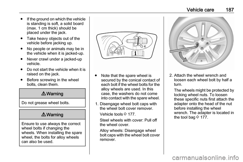
● Note that the spare wheel is secured by the conical contact ofeach bolt if the wheel bolts for the
alloy wheels are used. In this
case, the washers do not come
into contact with the spare wheel.
1. Disengage wheel bolt caps with the wheel bolt cover remover.
Vehicle tools 3 177.
Steel wheels with cover: Pull off
the wheel cover.
Alloy wheels: Disengage wheel
bolt caps with the wheel bolt cover remover.2. Attach the wheel wrench and loosen each wheel bolt by half a
turn.
The wheels might be protected by
locking wheel nuts. To loosen
these specific nuts first attach the
adapter onto the head of the nut
before installing the wheel
wrench. The adapter is located in
the tool bag 3 177.
Page 190 of 227
188Vehicle care
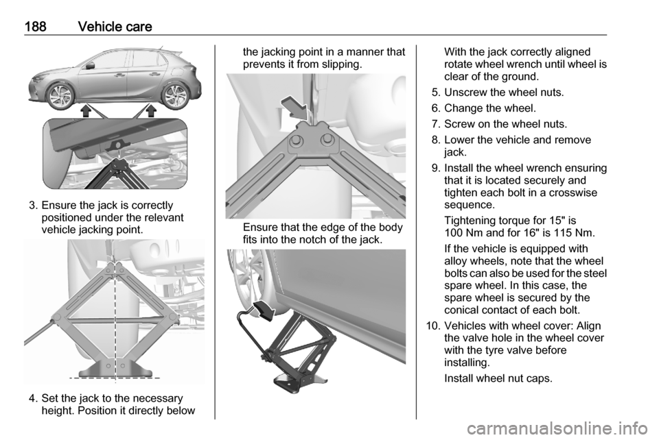
3. Ensure the jack is correctlypositioned under the relevant
vehicle jacking point.
4. Set the jack to the necessary height. Position it directly below
the jacking point in a manner that
prevents it from slipping.
Ensure that the edge of the body
fits into the notch of the jack.
With the jack correctly aligned
rotate wheel wrench until wheel is
clear of the ground.
5. Unscrew the wheel nuts.
6. Change the wheel.
7. Screw on the wheel nuts.
8. Lower the vehicle and remove jack.
9. Install the wheel wrench ensuring that it is located securely and
tighten each bolt in a crosswise
sequence.
Tightening torque for 15" is
100 Nm and for 16" is 115 Nm.
If the vehicle is equipped with
alloy wheels, note that the wheel
bolts can also be used for the steel spare wheel. In this case, the
spare wheel is secured by the
conical contact of each bolt.
10. Vehicles with wheel cover: Align the valve hole in the wheel cover
with the tyre valve before
installing.
Install wheel nut caps.
Page 191 of 227
Vehicle care18911. Stow the replaced wheel, thevehicle tools and the adapter for
the locking wheel nuts 3 177.
12. Check the tyre pressure of the installed tyre and the wheel nut
torque as soon as possible.
Stowing a damaged full size
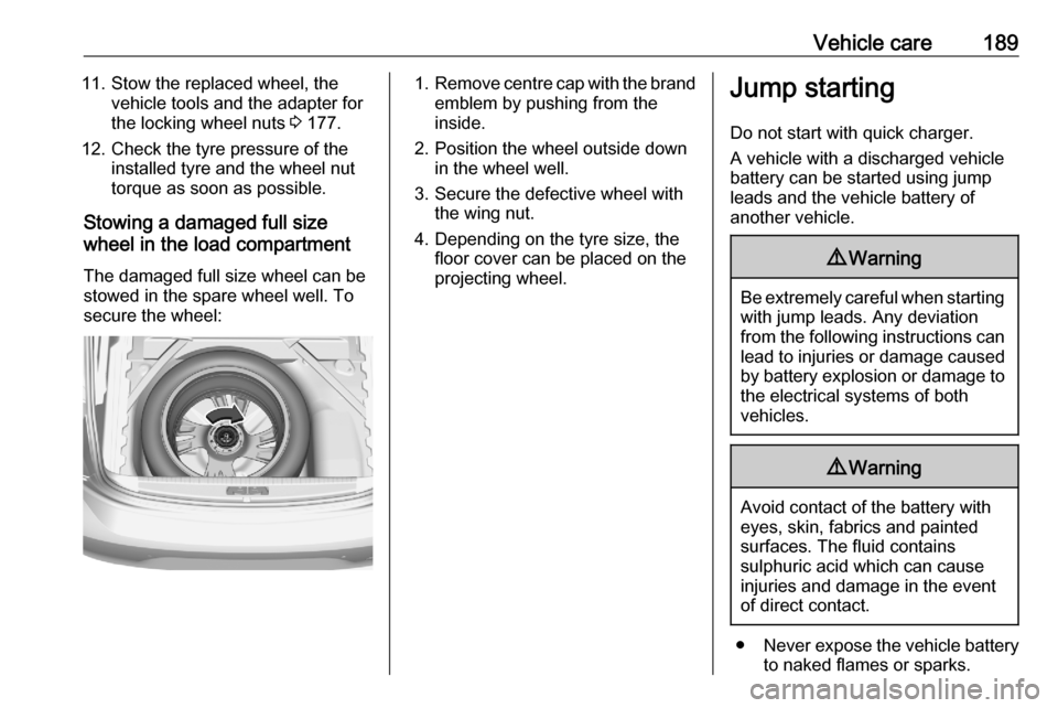
wheel in the load compartment
The damaged full size wheel can be
stowed in the spare wheel well. To
secure the wheel:1. Remove centre cap with the brand
emblem by pushing from the
inside.
2. Position the wheel outside down in the wheel well.
3. Secure the defective wheel with the wing nut.
4. Depending on the tyre size, the floor cover can be placed on the
projecting wheel.Jump starting
Do not start with quick charger.
A vehicle with a discharged vehicle
battery can be started using jump
leads and the vehicle battery of
another vehicle.9 Warning
Be extremely careful when starting
with jump leads. Any deviation
from the following instructions can
lead to injuries or damage caused
by battery explosion or damage to the electrical systems of both
vehicles.
9 Warning
Avoid contact of the battery with
eyes, skin, fabrics and painted
surfaces. The fluid contains
sulphuric acid which can cause
injuries and damage in the event
of direct contact.
● Never expose the vehicle battery
to naked flames or sparks.
Page 215 of 227

Customer information213unzipThis is version 2005-Feb-10 of theInfo-ZIP copyright and license. The
definitive version of this document
should be available at ftp://ftp.info-
zip.org/pub/infozip/license.html
indefinitely.
Copyright (c) 1990-2005 Info-ZIP. All
rights reserved.
For the purposes of this copyright and
license, “Info-ZIP” is defined as the
following set of individuals:
Mark Adler, John Bush, Karl Davis,
Harald Denker, Jean-Michel Dubois,
Jean-loup Gailly, Hunter Goatley, Ed
Gordon, Ian Gorman, Chris Herborth, Dirk Haase, Greg Hartwig, Robert
Heath, Jonathan Hudson, Paul
Kienitz, David Kirschbaum, Johnny
Lee, Onno van der Linden, Igor
Mandrichenko, Steve P. Miller, Sergio
Monesi, Keith Owens, George
Petrov, Greg Roelofs, Kai Uwe
Rommel, Steve Salisbury, Dave
Smith, Steven M. Schweda, Christian Spieler, Cosmin Truta, Antoine
Verheijen, Paul von Behren, Rich
Wales, Mike White.This software is provided “as is,” without warranty of any kind, express or implied. In no event shall Info-ZIP
or its contributors be held liable for
any direct, indirect, incidental, special
or consequential damages arising out
of the use of or inability to use this
software.
Permission is granted to anyone to
use this software for any purpose,
including commercial applications,
and to alter it and redistribute it freely,
subject to the following restrictions:
1. Redistributions of source code must retain the above copyright
notice, definition, disclaimer, and
this list of conditions.
2. Redistributions in binary form (compiled executables) must
reproduce the above copyright
notice, definition, disclaimer, and
this list of conditions in
documentation and/or other
materials provided with the
distribution. The sole exception to
this condition is redistribution of a
standard UnZipSFX binary
(including SFXWiz) as part of a
self-extracting archive; that ispermitted without inclusion of this
license, as long as the normal
SFX banner has not been
removed from the binary or
disabled.
3. Altered versions--including, but not limited to, ports to new
operating systems, existing ports
with new graphical interfaces, and dynamic, shared, or static library
versions--must be plainly marked
as such and must not be
misrepresented as being the
original source. Such altered
versions also must not be
misrepresented as being Info-ZIP
releases--including, but not
limited to, labeling of the altered
versions with the names “Info-
ZIP” (or any variation thereof,
including, but not limited to,
different capitalizations), “Pocket
UnZip,” “WiZ” or “MacZip” without the explicit permission of Info-ZIP.
Such altered versions are further
prohibited from misrepresentative
Page 226 of 227

224VVauxhall Connect .........................77
Vehicle battery ........................... 165
Vehicle checks............................ 162
Vehicle data ................................ 203
Vehicle data recording and privacy ..................................... 215
Vehicle dimensions .................... 207
Vehicle identification number ....201
Vehicle jack ................................ 177
Vehicle locator lighting .................87
Vehicle messages .......................75
Vehicle personalisation ...............76
Vehicle security ............................ 17
Vehicle specific data ......................3
Vehicle storage ........................... 161
Vehicle tools ............................... 177
Ventilation ..................................... 88
W
Warning chimes ........................... 76
Warning lights ............................... 62
Washer fluid ............................... 165
Wheel changing .........................184
Wheel covers ............................. 181
Wheels and tyres .......................177
Windows ....................................... 22
Windscreen................................... 22
Windscreen wiper and washer ....55Winter tyres ............................... 177
Wiper blade replacement ..........168