ECU VAUXHALL CROSSLAND X 2019.75 User Guide
[x] Cancel search | Manufacturer: VAUXHALL, Model Year: 2019.75, Model line: CROSSLAND X, Model: VAUXHALL CROSSLAND X 2019.75Pages: 247, PDF Size: 7.77 MB
Page 82 of 247
80Instruments and controlsService displayThe service system informs when to
change the engine oil and filter or a
vehicle service is required. Based on
driving conditions, the interval at
which an engine oil and filter change
is required can vary considerably.
Service information 3 213.
A required service due is displayed in the Driver Information Centre for7 seconds after switching on the
ignition.
If no service is required for the next
1800 miles or more no service
information appears in the display.
If service is required within the next
1800 miles, the remaining distance or
time duration is indicated for several
seconds. Simultaneously C lights
up permanently as reminder.
If service is required in less than
600 miles, C flashes and then
lights up permanently. Remaining
distance or time duration is indicated for several seconds.
Overdued service is indicated by a
message in the Driver Information
Centre which indicates the overdueddistance. C flashes and then lights
up permanently until service is
executed.
Reset of service interval
After each service, the service
indicator must be reset to ensure
proper functionality. It is
recommended to seek the assistance of a workshop.
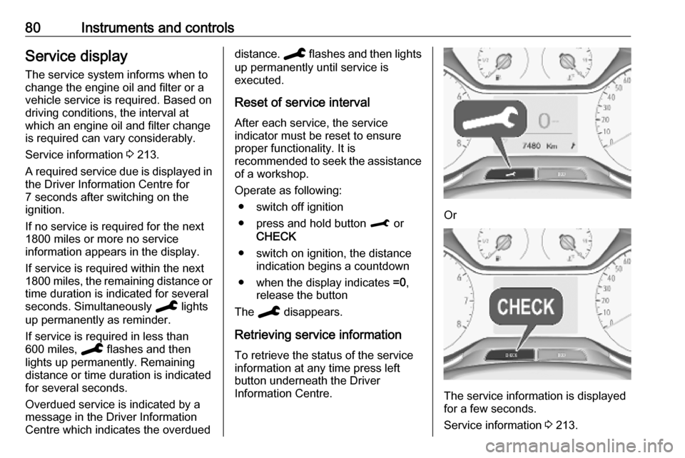
Operate as following: ● switch off ignition
● press and hold button M or
CHECK
● switch on ignition, the distance indication begins a countdown
● when the display indicates =0,
release the button
The C disappears.
Retrieving service information To retrieve the status of the service
information at any time press left
button underneath the Driver
Information Centre.
Or
The service information is displayed
for a few seconds.
Service information 3 213.
Page 99 of 247
Instruments and controls97Guide-me-home lighting:
Activates or deactivates the
function and adjusts its duration.
● Comfort
Mood lighting : Adjusts the
brightness of the ambient
lighting.
Rear wiper in reverse : Activates
or deactivates automatic
switching on of the rear window
wiper when reverse gear is
engaged.
● Vehicle access
Door unlock: boot only : Activates
or deactivates unlocking only the tailgate when pressing T on the
remote control.
Door unlock: driver only :
Changes the configuration to
unlock only the driver's door and
fuel filler flap or all doors, load
compartment and fuel filler flap
when pressing O on the remote
control.
● Safety
Driver attention warning :
Activates or deactivates the
driver drowsiness system.Driving functions
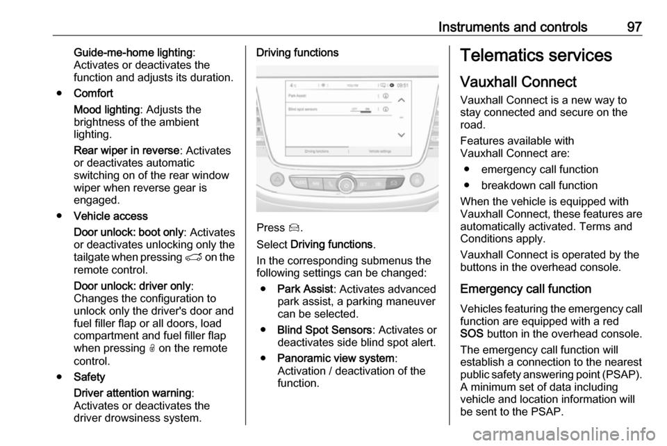
Press Í.
Select Driving functions .
In the corresponding submenus the
following settings can be changed:
● Park Assist : Activates advanced
park assist, a parking maneuver can be selected.
● Blind Spot Sensors : Activates or
deactivates side blind spot alert.
● Panoramic view system :
Activation / deactivation of the
function.
Telematics services
Vauxhall Connect
Vauxhall Connect is a new way to
stay connected and secure on the
road.
Features available with
Vauxhall Connect are:
● emergency call function
● breakdown call function
When the vehicle is equipped with
Vauxhall Connect , these features are
automatically activated. Terms and
Conditions apply.
Vauxhall Connect is operated by the
buttons in the overhead console.
Emergency call function Vehicles featuring the emergency call
function are equipped with a red
SOS button in the overhead console.
The emergency call function will
establish a connection to the nearest
public safety answering point (PSAP).
A minimum set of data including
vehicle and location information will
be sent to the PSAP.
Page 135 of 247
Driving and operating133Engine brakingTo utilise the engine braking effect,
select a lower gear in good time when
driving downhill, see manual mode.
Rocking the vehicle Rocking the vehicle is only
permissible if the vehicle is stuck in
sand, mud or snow. Move the selector
lever between D and R in a repeat
pattern. Do not race the engine and
avoid sudden acceleration.
Parking Apply the parking brake and engageP .Manual mode
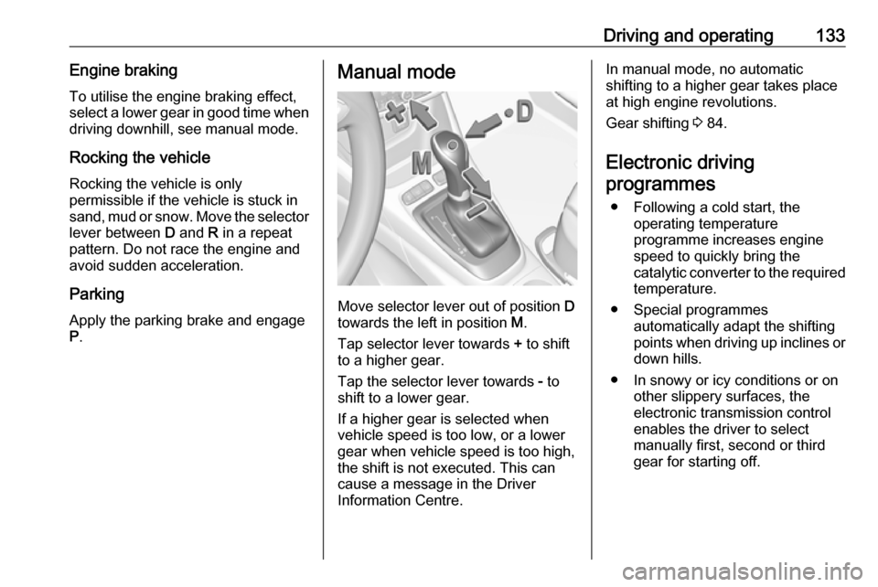
Move selector lever out of position D
towards the left in position M.
Tap selector lever towards + to shift
to a higher gear.
Tap the selector lever towards - to
shift to a lower gear.
If a higher gear is selected when
vehicle speed is too low, or a lower
gear when vehicle speed is too high,
the shift is not executed. This can
cause a message in the Driver
Information Centre.
In manual mode, no automatic
shifting to a higher gear takes place
at high engine revolutions.
Gear shifting 3 84.
Electronic driving programmes
● Following a cold start, the operating temperature
programme increases engine
speed to quickly bring the
catalytic converter to the required
temperature.
● Special programmes automatically adapt the shifting
points when driving up inclines or
down hills.
● In snowy or icy conditions or on other slippery surfaces, the
electronic transmission control
enables the driver to select
manually first, second or third gear for starting off.
Page 171 of 247
Driving and operating169Rear axle loadWhen the trailer is coupled and the
towing vehicle fully loaded, the
permissible rear axle load (see
identification plate or vehicle
documents) may be exceeded by
60 kg , the gross vehicle weight rating
must not be exceeded. If the
permissible rear axle load is
exceeded, a maximum speed of
60 mph applies.
Towing equipmentCaution
When operating without a trailer,
remove the coupling ball bar.
Stowage of coupling ball bar
The bag with the coupling ball bar is
stowed on the rear floor cover in the
load compartment.
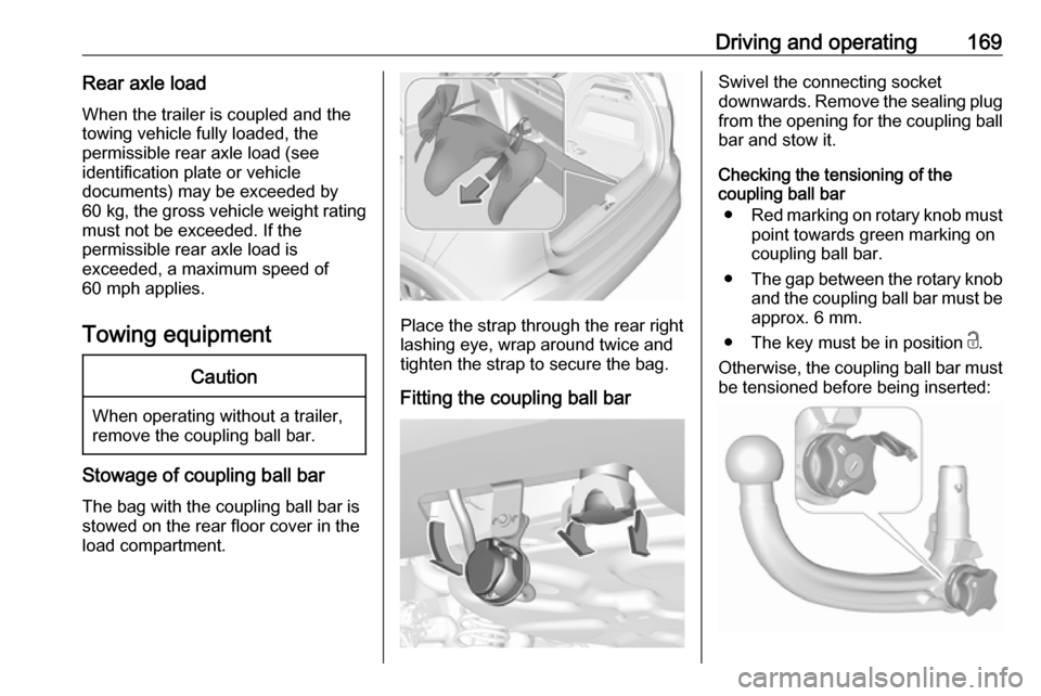
Place the strap through the rear right
lashing eye, wrap around twice and
tighten the strap to secure the bag.
Fitting the coupling ball bar
Swivel the connecting socket
downwards. Remove the sealing plug from the opening for the coupling ball
bar and stow it.
Checking the tensioning of the
coupling ball bar
● Red marking on rotary knob must
point towards green marking on
coupling ball bar.
● The gap between the rotary knob
and the coupling ball bar must be approx. 6 mm.
● The key must be in position c.
Otherwise, the coupling ball bar must
be tensioned before being inserted:
Page 173 of 247
Driving and operating1719Warning
Towing a trailer is permitted only
when a coupling ball bar is fitted correctly. If the coupling ball bardoes not engage correctly, seekthe assistance of a workshop.
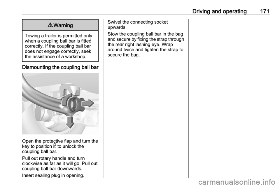
Dismounting the coupling ball bar
Open the protective flap and turn the
key to position c to unlock the
coupling ball bar.
Pull out rotary handle and turn
clockwise as far as it will go. Pull out coupling ball bar downwards.
Insert sealing plug in opening.
Swivel the connecting socket
upwards.
Stow the coupling ball bar in the bag
and secure by fixing the strap through the rear right lashing eye. Wrap
around twice and tighten the strap to
secure the bag.
Page 185 of 247
Vehicle care183Sidelight / daytime running light
In case of defective LEDs, have them replaced by a workshop.
LED headlights Headlights for low and high beam,
sidelights, daytime running lights and turn lights are designed as LEDs and
cannot be changed.
Have lights repaired by a workshop in
case of failure.
Front fog lights
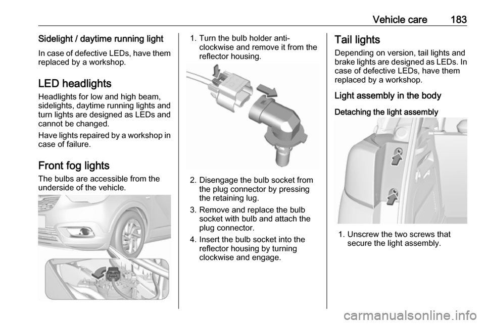
The bulbs are accessible from the
underside of the vehicle.1. Turn the bulb holder anti- clockwise and remove it from the
reflector housing.
2. Disengage the bulb socket from the plug connector by pressing
the retaining lug.
3. Remove and replace the bulb socket with bulb and attach the
plug connector.
4. Insert the bulb socket into the reflector housing by turning
clockwise and engage.
Tail lights
Depending on version, tail lights and
brake lights are designed as LEDs. In case of defective LEDs, have them
replaced by a workshop.
Light assembly in the body
Detaching the light assembly
1. Unscrew the two screws that secure the light assembly.
Page 187 of 247
Vehicle care185Pull straight out to remove from
the socket and replace.
Attaching the light assembly 1. Depending on version, attach the bulb carrier to the light assembly
and secure with the three screws
or attach turn light bulb socket.
2. Attach the light assembly to the vehicle body and secure with the
two screws.
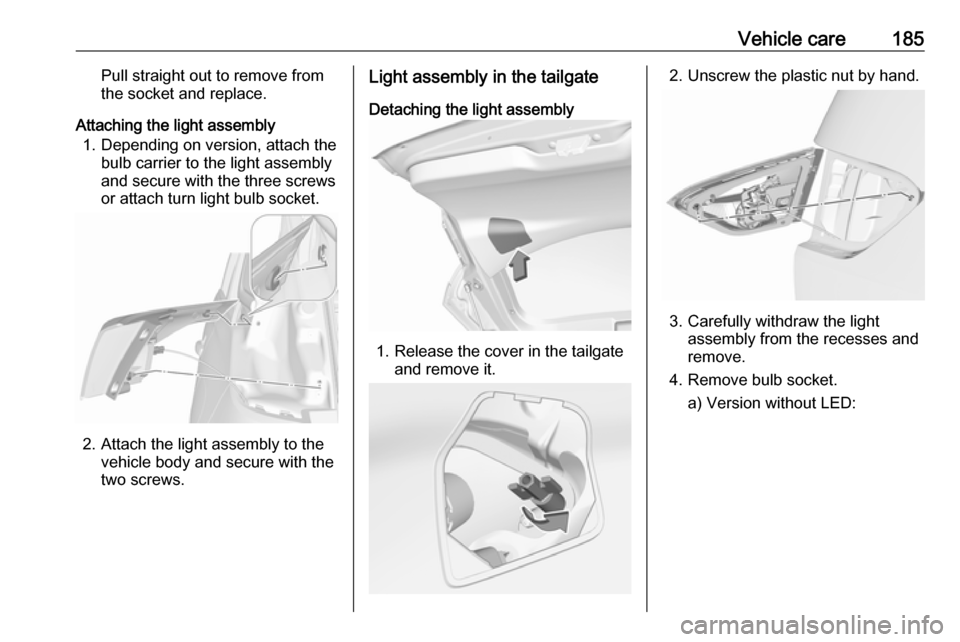
Light assembly in the tailgate
Detaching the light assembly
1. Release the cover in the tailgate and remove it.
2. Unscrew the plastic nut by hand.
3. Carefully withdraw the lightassembly from the recesses and
remove.
4. Remove bulb socket. a) Version without LED:
Page 189 of 247
Vehicle care187
2. Attach the light assembly to thetailgate.
3. Secure the light assembly with the
plastic nut.
4. Attach the cover to the tailgate.
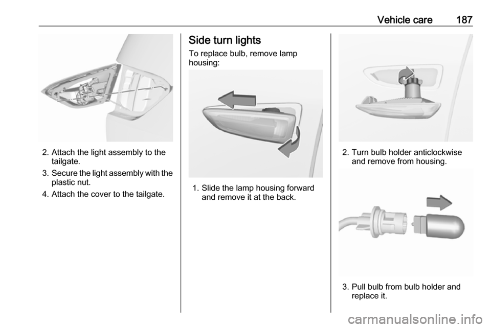
Side turn lights
To replace bulb, remove lamp
housing:
1. Slide the lamp housing forward and remove it at the back.
2. Turn bulb holder anticlockwiseand remove from housing.
3. Pull bulb from bulb holder and replace it.
Page 194 of 247
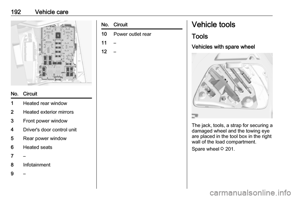
192Vehicle careNo.Circuit1Heated rear window2Heated exterior mirrors3Front power window4Driver's door control unit5Rear power window6Heated seats7–8Infotainment9–No.Circuit10Power outlet rear11–12–Vehicle tools
Tools
Vehicles with spare wheel
The jack, tools, a strap for securing a damaged wheel and the towing eye
are placed in the tool box in the right
wall of the load compartment.
Spare wheel 3 201.
Page 204 of 247
202Vehicle careCaution
The use of a spare wheel that issmaller than the other wheels or in combination with winter tyres
could affect driveability. Have the defective tyre replaced as soon as
possible.
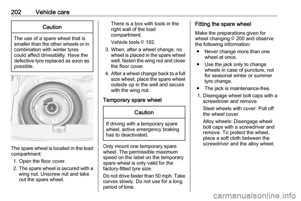
The spare wheel is located in the load
compartment:
1. Open the floor cover.
2. The spare wheel is secured with a
wing nut. Unscrew nut and take
out the spare wheel.
There is a box with tools in the
right wall of the load compartment.
Vehicle tools 3 192.
3. When, after a wheel change, no wheel is placed in the spare wheelwell, fasten the wing nut and close
the floor cover.
4. After a wheel change back to a full
size wheel, place the spare wheel
outside up in the well and secure
with the wing nut.
Temporary spare wheelCaution
If driving with a temporary spare
wheel, active emergency braking
has to deactivated.
Only mount one temporary spare
wheel. The permissible maximum
speed on the label on the temporary
spare wheel is only valid for the
factory-fitted tyre size.
Do not drive faster than 50 mph. Take curves slowly. Do not use for a long
period of time.
Fitting the spare wheel
Make the preparations given for
wheel changing 3 200 and observe
the following information:
● Never change more than one wheel at once.
● Use the jack only to change wheels in case of puncture, not
for seasonal winter or summer
tyre change.
● The jack is maintenance-free.
1. Disengage wheel bolt caps with a
screwdriver and remove.
Steel wheels with cover: Pull off
the wheel cover.
Alloy wheels: Disengage wheel
bolt caps with a screwdriver and
remove. To protect the wheel,
place a soft cloth between the
screwdriver and the alloy wheel.