tow VAUXHALL CROSSLAND X 2019.75 Owner's Guide
[x] Cancel search | Manufacturer: VAUXHALL, Model Year: 2019.75, Model line: CROSSLAND X, Model: VAUXHALL CROSSLAND X 2019.75Pages: 247, PDF Size: 7.77 MB
Page 149 of 247

Driving and operating147more sensitive. Therefore, pressing
the brake pedal less strongly results
in immediate hard braking. This
function helps the driver brake
quicker and harder before the
imminent collision.9 Warning
Active emergency braking is not
designed to apply hard
autonomous braking or to
automatically avoid a collision. It is designed to reduce the vehicle
speed before a collision. It may not
react to animals. After a sudden
lane change, the system needs a
certain time to detect the next
preceding vehicle.
The complete attention of the
driver is always required while
driving. The driver must always be
ready to take action and apply the brakes and steer to avoid
collisions.
The system is designed to work with
all occupants wearing their seat belts.
Forward collision alert 3 144.
Front pedestrian protection 3 148.
System limitations In some cases, the active emergencybraking system may provide an
automatic braking in situations that
seem to be unnecessary, for instance
in parking garages, due to traffic signs in a curve or due to vehicles in
another lane. This is normal
operation, the vehicle does not need
service. Firmly apply the accelerator
pedal to override the automatic
braking if the situation and the
surroundings permit.
In the following cases, active
emergency braking performance is limited:
● driving on winding or hilly roads
● detecting all vehicles, especially vehicles with a trailer, tractors,
muddy vehicles, etc.
● detecting a vehicle when weather
limits visibility, such as in fog,
rain, or snow
● driving in the dark
● windscreen damaged or stickeredComplete attention is always required
while driving, and you should be
ready to take action and apply the
brakes and / or steer the vehicle to
avoid crashes.
We recommend to deactivate the
system in the vehicle personalisation
in the following cases:
● when towing a trailer or caravan
● when carrying long objects on roof bars or a roof rack
● when the vehicle is being towed with the engine running
● when a spare wheel is fitted that is smaller than the other wheels
● before using an automatic car wash with the engine running
● before placing the vehicle on a rolling road in a workshop
● if the windscreen has been damaged close to the camera
● if the front bumper has been damaged
● if the brake lamps are not working
Active emergency braking can be
deactivated in the personalisation
menu 3 94. If deactivated, m
Page 155 of 247
Driving and operating153The system will not identify slots that
are clearly smaller or larger than the
vehicle.
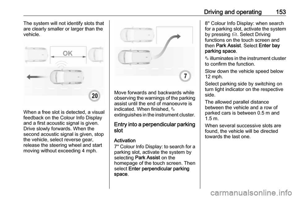
When a free slot is detected, a visual
feedback on the Colour Info Display
and a first acoustic signal is given.
Drive slowly forwards. When the second acoustic signal is given, stop
the vehicle, select reverse gear,
release the steering wheel and start
moving without exceeding 4 mph.
Move forwards and backwards while
observing the warnings of the parking
assist until the end of manoeuvre is
indicated. When finished, $
extinguishes in the instrument cluster.
Entry into a perpendicular parking
slot
Activation
7'' Colour Info Display: to search for a parking slot, activate the system by
selecting Park Assist on the
homepage of the touch screen. Then
select Enter perpendicular parking
space .
8'' Colour Info Display: when search
for a parking slot, activate the system
by pressing Í. Select Driving
functions on the touch screen and
then Park Assist . Select Enter bay
parking space .
$ illuminates in the instrument cluster
to confirm the function.
Slow down the vehicle speed below
12 mph.
Select parking side by switching on
turn light indicator on the respective
side.
The allowed parallel distance
between the vehicle and a row of
parked cars is between 0.5 m and
1.5 m.
When several successive slots are found, the vehicle will be directed
towards the last one.
Page 169 of 247
Driving and operating167
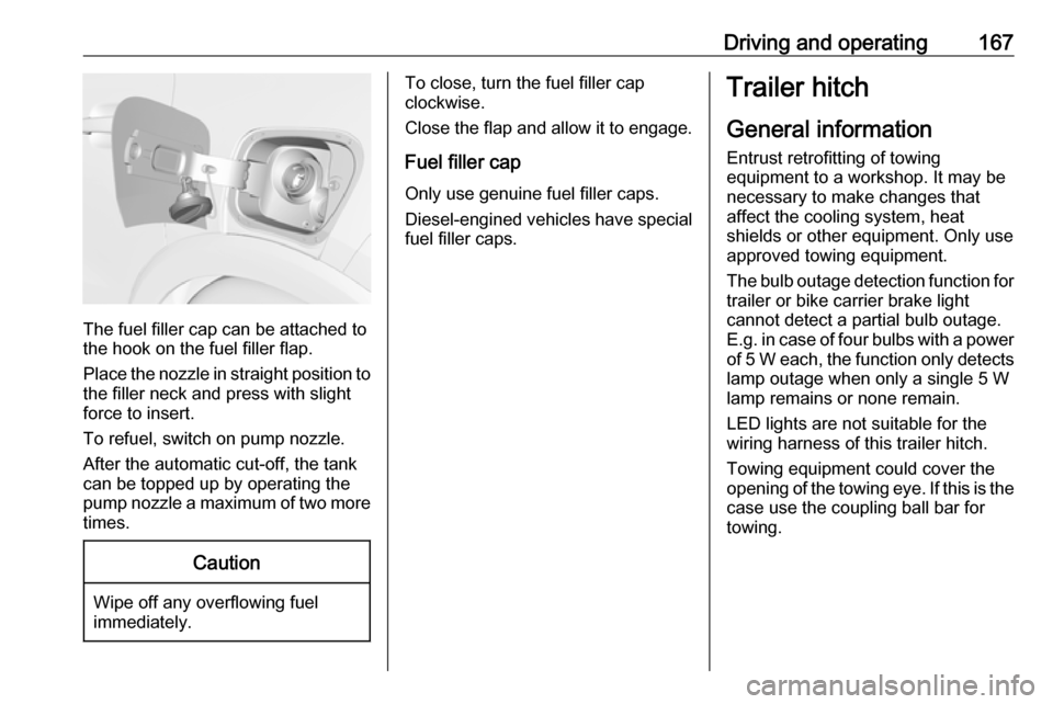
The fuel filler cap can be attached to
the hook on the fuel filler flap.
Place the nozzle in straight position to the filler neck and press with slight
force to insert.
To refuel, switch on pump nozzle.
After the automatic cut-off, the tank can be topped up by operating the
pump nozzle a maximum of two more
times.
Caution
Wipe off any overflowing fuel
immediately.
To close, turn the fuel filler cap
clockwise.
Close the flap and allow it to engage.
Fuel filler cap
Only use genuine fuel filler caps.
Diesel-engined vehicles have special fuel filler caps.Trailer hitch
General information
Entrust retrofitting of towing
equipment to a workshop. It may be
necessary to make changes that
affect the cooling system, heat
shields or other equipment. Only use
approved towing equipment.
The bulb outage detection function for
trailer or bike carrier brake light
cannot detect a partial bulb outage.
E.g. in case of four bulbs with a power
of 5 W each, the function only detects lamp outage when only a single 5 W
lamp remains or none remain.
LED lights are not suitable for the
wiring harness of this trailer hitch.
Towing equipment could cover the
opening of the towing eye. If this is the case use the coupling ball bar for
towing.
Page 170 of 247

168Driving and operatingDriving characteristics andtowing tips
Before attaching a trailer, lubricate the coupling ball. However, do not do
so if a stabiliser, which acts on the coupling ball, is being used to reduce snaking movements.
During trailer towing do not exceed a
speed of 50 mph. A maximum speed
of 60 mph is only appropriate if an
oscillation damper is used and the
permissible gross trailer weight does
not exceed the vehicle's curb weight.
For trailers with low driving stability
and caravan trailers, the use of an
oscillation damper is strongly
recommended.
If the trailer starts snaking, drive more slowly, do not attempt to correct the
steering and brake sharply if
necessary.
When driving downhill, drive in the
same gear as if driving uphill and
drive at a similar speed.
Adjust tyre pressure to the value
specified for full load 3 227.Trailer towing
Trailer loads The permissible trailer loads are
vehicle and engine-dependent
maximum values which must not be
exceeded. The actual trailer load is the difference between the actual
gross weight of the trailer and the
actual coupling socket load with the
trailer coupled.
The permissible trailer loads are
specified in the vehicle documents. In general, they are valid for inclines up
to 12%.
The permissible trailer load applies
up to the specified incline and at sea
level. Since engine power decreases
as altitude increases due to the air
becoming thinner, therefore reducing
climbing ability, the permissible gross
train weight also decreases by 10%
for every 1000 m of altitude. The
gross train weight does not have to be reduced when driving on roads with
slight inclines (less than 8%, e.g.
motorways).The permissible gross train weight must not be exceeded. This weight is
specified on the identification plate
3 219.
Vertical coupling load
The vertical coupling load is the load
exerted by the trailer on the coupling
ball. It can be varied by changing the
weight distribution when loading the
trailer.
The maximum permissible vertical
coupling load of 65 kg is specified on the towing equipment identification
plate and in the vehicle documents.
For vehicles with engine DV5RC and
automatic transmission, the
maximum permissible vertical
coupling load is 55 kg. Always aim for the maximum load, especially in the
case of heavy trailers. The vertical
coupling load should never fall below
25 kg.
Page 171 of 247
Driving and operating169Rear axle loadWhen the trailer is coupled and the
towing vehicle fully loaded, the
permissible rear axle load (see
identification plate or vehicle
documents) may be exceeded by
60 kg , the gross vehicle weight rating
must not be exceeded. If the
permissible rear axle load is
exceeded, a maximum speed of
60 mph applies.
Towing equipmentCaution
When operating without a trailer,
remove the coupling ball bar.
Stowage of coupling ball bar
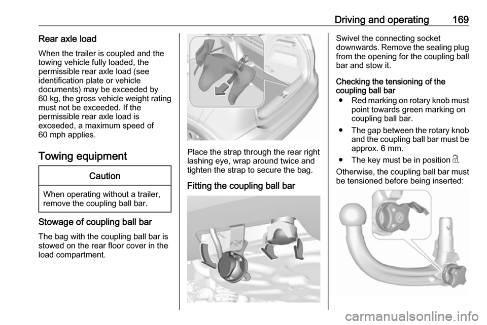
The bag with the coupling ball bar is
stowed on the rear floor cover in the
load compartment.
Place the strap through the rear right
lashing eye, wrap around twice and
tighten the strap to secure the bag.
Fitting the coupling ball bar
Swivel the connecting socket
downwards. Remove the sealing plug from the opening for the coupling ball
bar and stow it.
Checking the tensioning of the
coupling ball bar
● Red marking on rotary knob must
point towards green marking on
coupling ball bar.
● The gap between the rotary knob
and the coupling ball bar must be approx. 6 mm.
● The key must be in position c.
Otherwise, the coupling ball bar must
be tensioned before being inserted:
Page 172 of 247
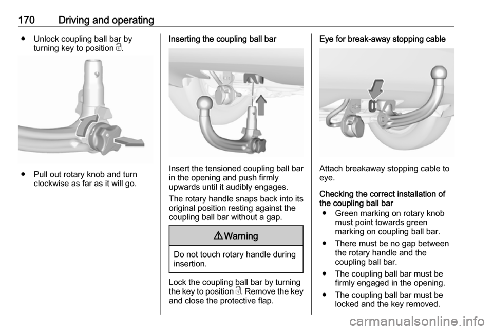
170Driving and operating● Unlock coupling ball bar byturning key to position c.
● Pull out rotary knob and turn
clockwise as far as it will go.
Inserting the coupling ball bar
Insert the tensioned coupling ball bar
in the opening and push firmly
upwards until it audibly engages.
The rotary handle snaps back into its
original position resting against the
coupling ball bar without a gap.
9 Warning
Do not touch rotary handle during
insertion.
Lock the coupling ball bar by turning
the key to position c. Remove the key
and close the protective flap.
Eye for break-away stopping cable
Attach breakaway stopping cable to
eye.
Checking the correct installation of
the coupling ball bar
● Green marking on rotary knob must point towards green
marking on coupling ball bar.
● There must be no gap between the rotary handle and the
coupling ball bar.
● The coupling ball bar must be firmly engaged in the opening.
● The coupling ball bar must be locked and the key removed.
Page 173 of 247
Driving and operating1719Warning
Towing a trailer is permitted only
when a coupling ball bar is fitted correctly. If the coupling ball bardoes not engage correctly, seekthe assistance of a workshop.
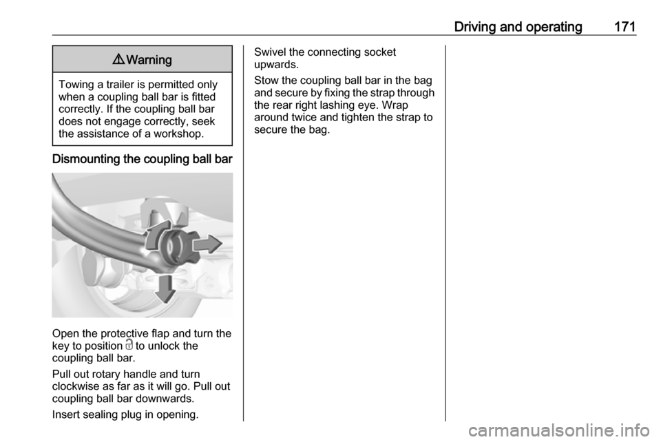
Dismounting the coupling ball bar
Open the protective flap and turn the
key to position c to unlock the
coupling ball bar.
Pull out rotary handle and turn
clockwise as far as it will go. Pull out coupling ball bar downwards.
Insert sealing plug in opening.
Swivel the connecting socket
upwards.
Stow the coupling ball bar in the bag
and secure by fixing the strap through the rear right lashing eye. Wrap
around twice and tighten the strap to
secure the bag.
Page 174 of 247

172Vehicle careVehicle careGeneral Information...................172
Accessories and vehicle modifications .......................... 172
Vehicle storage ........................173
End-of-life vehicle recovery .....173
Vehicle checks ........................... 174
Performing work ......................174
Bonnet ..................................... 174
Engine oil ................................. 175
Engine coolant ......................... 176
Washer fluid ............................ 176
Brakes ..................................... 177
Brake fluid ............................... 177
Vehicle battery ......................... 177
Diesel fuel system bleeding .....179
Wiper blade replacement ........179
Bulb replacement .......................180
Halogen headlights ..................180
LED headlights ........................ 183
Front fog lights ......................... 183
Tail lights ................................. 183
Side turn lights ......................... 187
Number plate light ...................188
Interior lights ............................ 188Electrical system........................188
Fuses ....................................... 188
Engine compartment fuse box . 189
Instrument panel fuse box .......190
Vehicle tools .............................. 192
Tools ........................................ 192
Wheels and tyres .......................193
Winter tyres ............................. 193
Tyre designations ....................193
Tyre pressure .......................... 194
Tyre deflation detection system .................................... 195
Tread depth ............................. 196
Changing tyre and wheel size . 196
Wheel covers ........................... 196
Tyre chains .............................. 197
Tyre repair kit .......................... 197
Wheel changing .......................200
Spare wheel ............................ 201
Jump starting ............................. 205
Towing ....................................... 206
Towing the vehicle ...................206
Towing another vehicle ...........207
Appearance care .......................208
Exterior care ............................ 208
Interior care ............................. 210
Floor mats ............................... 211General Information
Accessories and vehicle modifications
We recommend the use of genuine parts and accessories and factory
approved parts specific for this
vehicle type. We cannot assess or
guarantee reliability of other products - even if they have a regulatory or
otherwise granted approval.
Any modification, conversion or other
changes made to standard vehicle
specifications (including, without
limitation, software modifications,
modifications of the electronic control units) may invalidate the warranty
offered by Vauxhall.
Furthermore, such changes may
affect driver assistance systems, may
impact fuel consumption, CO 2
emissions and other emissions of the
vehicle and cause the vehicle to no
longer conform to the operating
permit, impacting the validity of your
vehicle registration.
Page 194 of 247
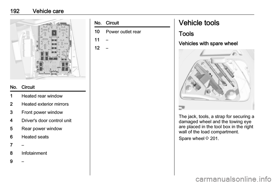
192Vehicle careNo.Circuit1Heated rear window2Heated exterior mirrors3Front power window4Driver's door control unit5Rear power window6Heated seats7–8Infotainment9–No.Circuit10Power outlet rear11–12–Vehicle tools
Tools
Vehicles with spare wheel
The jack, tools, a strap for securing a damaged wheel and the towing eye
are placed in the tool box in the right
wall of the load compartment.
Spare wheel 3 201.
Page 195 of 247
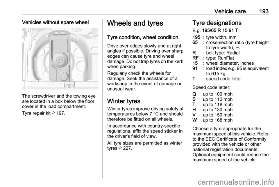
Vehicle care193Vehicles without spare wheel
The screwdriver and the towing eye
are located in a box below the floor
cover in the load compartment.
Tyre repair kit 3 197.
Wheels and tyres
Tyre condition, wheel condition Drive over edges slowly and at right
angles if possible. Driving over sharp
edges can cause tyre and wheel
damage. Do not trap tyres on the kerb when parking.
Regularly check the wheels for
damage. Seek the assistance of a
workshop in the event of damage or
unusual wear.
Winter tyres
Winter tyres improve driving safety at temperatures below 7 °C and shouldtherefore be fitted on all wheels.
In accordance with country-specific
regulations, affix the speed sticker in
the driver's field of view.
All tyre sizes are permitted as winter
tyres 3 227.Tyre designations
E.g. 195/65 R 15 91 T195:tyre width, mm65:cross-section ratio (tyre height
to tyre width), %R:belt type: RadialRF:type: RunFlat15:wheel diameter, inches91:load index e.g. 95 is equivalent
to 615 kgT:speed code letter
Speed code letter:
Q:up to 100 mphS:up to 112 mphT:up to 118 mphH:up to 130 mphV:up to 150 mphW:up to 168 mph
Choose a tyre appropriate for the
maximum speed of this vehicle. Refer to the EEC Certificate of Conformity
provided with the vehicle or other
national registration documents.
Optional equipment could reduce the
maximum speed of the vehicle.