warning VAUXHALL CROSSLAND X 2019 Manual PDF
[x] Cancel search | Manufacturer: VAUXHALL, Model Year: 2019, Model line: CROSSLAND X, Model: VAUXHALL CROSSLAND X 2019Pages: 261, PDF Size: 7.98 MB
Page 169 of 261

Driving and operating167Display indicationThe instructions on the display show: ● General hints and warning messages.
● The demand to stop the vehicle, when a parking slot is detected.
● The direction of driving during the
parking manoeuvre.
● The demand to shift into reverse or first gear.
● The demand to stop or to drive slowly.
● The successful completion of the
parking manoeuvre indicated by
a pop-up symbol and a chime.
● The cancelling of a parking manoeuvre.
Deactivation The current park assist manoeuvre is
cancelled via the button to return to
the previous screen in the Colour Info Display. To deactivate the system
completely, press r Off in the
centre console.The system is deactivated
automatically:
● if the ignition is switched off
● if stalling the engine
● if no manoeuvre is started within 5 minutes of selection of the typeof manoeuvre
● after a prolonged stop of the vehicle during a manoeuvre
● if the electronic stability control (ESC) is triggered
● if the speed of the vehicle exceeds the stated limit
● when the driver interrupts movement of the steering wheel
● after 4 manoeuvre cycles
● on opening the driver's door
● if one of the front wheels encounters an obstacle
● parking manoeuvre successfully ended
Deactivation by the driver or by the system during manoeuvring will beindicated on the display. Additionally,
an acoustic signal sounds.The system is switched off
automatically when towing a
electrically connected trailer.
Contact your dealer to switch off the
system for a prolonged period.
Fault
In the event of a fault, $ flashes for a
few seconds, accompanied by an
acoustic signal. If the fault occurs
during the use of the system, $
extinguishes.
In the event of a fault in the power
steering, c flashes in the instrument
panel, accompanied by a message.9 Warning
Under certain circumstances,
various reflective surfaces on
objects or clothing as well as
external noise sources may cause the system to fail to detect
obstacles.
Special attention must be paid to
low obstacles which can damage
the lower part of the bumper.
Page 170 of 261
168Driving and operatingCaution
Performance of the system can bereduced when sensors are
covered, e.g. by ice or snow.
Performance of the parking assist
system can be reduced due to
heavy loading.
Special conditions apply if there
are taller vehicles in the vicinity
(e.g. off-road vehicles, mini vans,
vans). Object identification and correct distance indication in the
upper part of these vehicles
cannot be guaranteed.
Objects with a very small reflection
cross-section, e.g. objects of
narrow size or soft materials, may
not be detected by the system.
Parking assist systems do not
detect objects outside the
detection range.
Notice
It is possible that the sensor detects a non-existing object caused by
echo disturbance from external
acoustic noise or mechanical
misalignments (sporadic false
warnings may occur).
Make sure that the front number
plate is properly mounted (not bent
and no gaps to the bumper on the left
or right side) and the sensors are
firmly in place.
Advanced parking assist system
may not respond to changes in the
available parking space after
initiating a parking manoeuvre. The
system may recognize an entry, a
gateway, a courtyard or even a crossing as a parking slot. After
selecting reverse gear the system
will start a parking manoeuvre. Take care regarding the availability of the
suggested parking slot.
Surface irregularities, e.g. on construction zones, are not detected
by the system. The driver accepts
responsibility.
Side blind spot alert The side blind spot alert system
detects and reports objects on either
side of the vehicle, within a specified
blind spot zone. The system displaysa visual alert in each exterior mirror,
when detecting objects that may not
be visible in the interior and exterior
mirrors.
Side blind spot alert uses some of the
advanced parking assist sensors
which are located in the front and rear bumper on both sides of the vehicle.9 Warning
Side blind spot alert does not
replace driver vision.
The system does not detect:
● vehicles outside the side blind zones which may be rapidly
approaching
● pedestrians, cyclists or animals
Before changing a lane, always
check all mirrors, look over the
shoulder and use the turn light.
Activation
7'' Colour Info Display: select Blind
spot monitoring on the Info Display
and activate the function.
Page 174 of 261
172Driving and operatingDeactivation
Panoramic view system is
deactivated when:
● driving faster than 6 mph
● 7 seconds after disengaging reverse gear
● by pressing the icon q in the left
upper corner of the touch screen
● opening the tailgate
General information9 Warning
The panoramic view system does
not replace driver vision. It will not display children, pedestrians,
cyclists, crossing traffic, animals,
or any other objects outside of the camera view area, e. g. below the
bumper, or underneath the
vehicle.
Do not drive or park the vehicle
using only the panoramic view
system.
Always check the surrounding of
the vehicle before driving.
Displayed images may be further
or closer than they appear. The
area displayed is limited and
objects that are close to either
edge of the bumper or under the
bumper are not displayed on the
screen.
System limitations
Caution
For optimal operation of the
system, it is important to keep the
lense of the camera in the tailgate between the number plate lightsalways clean. Rinse the lense with water and wipe with a soft cloth.
Do not clean the lense with a
steam-jet or high-pressure jet
cleaner.
The panoramic view system may not
operate properly when:
● The surrounding is dark.
● The sun or the beam of headlights is shining directly into
the camera lenses.
● During nighttime driving.
● Weather limits visibility, such as fog, rain, or snow.
● The camera lenses are blocked by snow, ice, slush, mud, dirt.
● The vehicle is towing a trailer.
● The vehicle had an accident.
● There are extreme temperature changes.
Rear view camera The rear view camera assists the
driver when reversing by displaying a
view of the area behind the vehicle.
The view of the camera is displayed
in the Info Display.9 Warning
The rear view camera does not
replace driver vision. Note that
objects that are outside the
camera's field of view and the
Page 176 of 261
174Driving and operating● The camera lenses are blockedby snow, ice, slush, mud, dirt.Clean the lense, rinse with water,
and wipe with a soft cloth.
● The tailgate will be opened.
● The vehicle is towing an electrically connected trailer.
● The vehicle had a rear end accident.
● There are extreme temperature changes.
Lane departure warning The lane departure warning system
observes the lane markings between
which the vehicle is driving via a front camera. The system detects lane
changes and warns the driver in the
event of an unintended lane change
via visual and acoustic signals.
Criteria for the detection of an
unintended lane change are:
● No operation of turn lights.
● No brake pedal operation.
● No active accelerator operation or speeding-up.If the driver is active, no warning will
be issued.
Activation
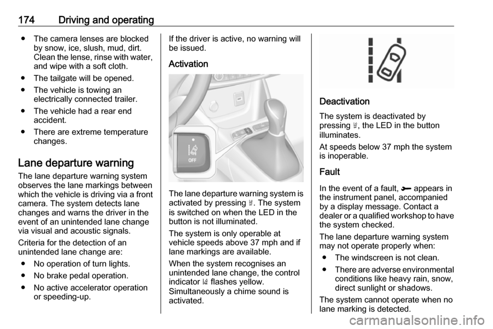
The lane departure warning system isactivated by pressing ½. The system
is switched on when the LED in the
button is not illuminated.
The system is only operable at
vehicle speeds above 37 mph and if
lane markings are available.
When the system recognises an
unintended lane change, the control
indicator ) flashes yellow.
Simultaneously a chime sound is
activated.
Deactivation
The system is deactivated by
pressing ½, the LED in the button
illuminates.
At speeds below 37 mph the system
is inoperable.
Fault
In the event of a fault, R appears in
the instrument panel, accompanied
by a display message. Contact a
dealer or a qualified workshop to have the system checked.
The lane departure warning system may not operate properly when:
● The windscreen is not clean.
● There are adverse environmental
conditions like heavy rain, snow,
direct sunlight or shadows.
The system cannot operate when no
lane marking is detected.
Page 177 of 261
Driving and operating175System limitationsThe system performance may not
operate properly when:
● Vehicle speed is below 37 mph.
● Driving on winding or hilly roads.
● During nighttime driving.
● Weather limits visibility, such as fog, rain, or snow.
● The sensor in the windscreen is blocked by snow, ice, slush, mud,dirt, windscreen damage or
affected by foreign items, e.g.
stickers.
● The sun is shining directly into the camera lens.
● Close vehicles ahead.
● Banked roads.
● Road edges.
● Roads with poor lane markings.
● Sudden lighting changes.
Driver alert
The driver alert system monitores the driving time and the vigilance of the
driver. Monitoring the vigilance of thedriver is based on the trajectory
variations of the vehicle compared to
the lane markings.
The system includes a driving time alert combined with driver drowsiness
detection.9 Warning
The system cannot replace the
need for vigilance on the part of
the driver. It is recommended that
you take a break as soon as you
feel tired or at least every two
hours. Do not take the wheel if you are tired.
Activation or Deactivation
The system can be activated or
deactivated in the vehicle
personalisation 3 101.
The state of the system stays in
memory when the ignition is switched
off.
Driving time alert
The driver gets notified by a pop-upreminder symbol € in the Driver
Information Centre simultaneously with an acoustic alert if the driver has
not taken a break after 2 hours of
driving at a speed above 40 mph. The alert is repeated hourly until the
vehicle is stopped, no matter how
vehicle speed evolves.
The counting of driving time alert is
reset when the ignition has been
switched off for a few minutes.
Driver drowsiness detection
The system monitors the driver's level
of vigilance. A camera at the top of the windscreen detects variations in
trajectory compared to the lane
markings. This system is particularly
suited to fast roads (speed higher
than 40 mph).
If the trajectory of the vehicle
suggests a certain level of
drowsiness or inattention by the
driver, the system triggers the first
Page 183 of 261
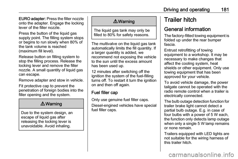
Driving and operating181EURO adapter: Press the filler nozzle
onto the adapter. Engage the locking
lever of the filler nozzle.
Press the button of the liquid gas supply point. The filling system stops
or begins to run slowly when 80% of
the tank volume is reached
(maximum fill level).
Release button on filling system to stop the filling process. Release the
locking lever and remove the filler
nozzle. A small quantity of liquid gas
can escape.
Remove adapter and stow in vehicle.
Fit protective cap to prevent the
penetration of foreign bodies into the
filler opening and the system.9 Warning
Due to the system design, an
escape of liquid gas after
releasing the locking lever is
unavoidable. Avoid inhaling.
9 Warning
The liquid gas tank may only be
filled to 80% for safety reasons.
The multivalve on the liquid gas tank
automatically limits the fill quantity. If
a larger quantity is added, we
recommend not exposing the vehicle
to the sun until the excess amount
has been used up.
12 minutes after switching off the
ignition the system of the fuel-filling
turns off. To restart it turn the ignition
on and then off again.
Fuel filler cap Only use genuine fuel filler caps.Diesel-engined vehicles have special
fuel filler caps.
Trailer hitch
General information
The factory-fitted towing equipment is
folded up under the rear bumper
fascia.
Entrust retrofitting of towing
equipment to a workshop. It may be
necessary to make changes that
affect the cooling system, heat
shields or other equipment. Only use
towing equipment that has been
approved for your vehicle.
To avoid vehicle damage, the power
tailgate cannot be operated with the
radio remote control when a trailer is
electrically connected.
The bulb outage detection function for trailer brake light cannot detect a
partial bulb outage. E.g. in case of
four bulbs with a power of 5 W each,
the function only detects lamp outage when only a single 5 W lamp remains
or none remain.
Trailers equipped with LED lights are
not suitable for the wiring harness of
this trailer hitch.
Page 186 of 261
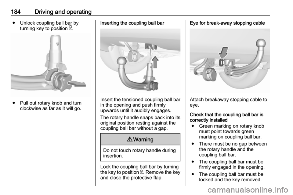
184Driving and operating● Unlock coupling ball bar byturning key to position c.
● Pull out rotary knob and turn
clockwise as far as it will go.
Inserting the coupling ball bar
Insert the tensioned coupling ball bar
in the opening and push firmly
upwards until it audibly engages.
The rotary handle snaps back into its
original position resting against the
coupling ball bar without a gap.
9 Warning
Do not touch rotary handle during
insertion.
Lock the coupling ball bar by turning
the key to position e. Remove the key
and close the protective flap.
Eye for break-away stopping cable
Attach breakaway stopping cable to
eye.
Check that the coupling ball bar is correctly installed
● Green marking on rotary knob must point towards green
marking on coupling ball bar.
● There must be no gap between the rotary handle and the
coupling ball bar.
● The coupling ball bar must be firmly engaged in the opening.
● The coupling ball bar must be locked and the key removed.
Page 187 of 261
Driving and operating1859Warning
Towing a trailer is permitted only
when a coupling ball bar is fitted correctly. If the coupling ball bardoes not engage correctly, seekthe assistance of a workshop.
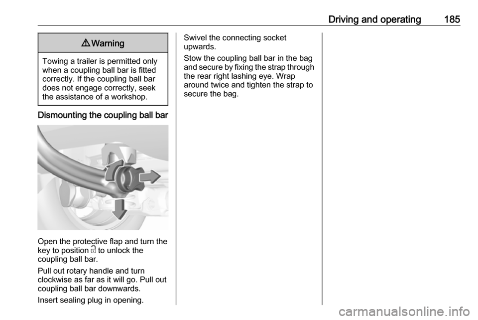
Dismounting the coupling ball bar
Open the protective flap and turn the
key to position c to unlock the
coupling ball bar.
Pull out rotary handle and turn
clockwise as far as it will go. Pull out coupling ball bar downwards.
Insert sealing plug in opening.
Swivel the connecting socket
upwards.
Stow the coupling ball bar in the bag
and secure by fixing the strap through the rear right lashing eye. Wrap
around twice and tighten the strap to
secure the bag.
Page 190 of 261
188Vehicle careVehicle checks
Performing work9 Warning
Only perform engine compartment
checks when the ignition is off.
The cooling fan may start
operating even if the ignition is off.
9 Danger
The ignition system uses
extremely high voltage. Do not
touch.
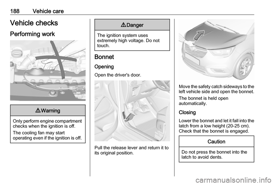
Bonnet
Opening
Open the driver's door.
Pull the release lever and return it to
its original position.
Move the safety catch sideways to the
left vehicle side and open the bonnet.
The bonnet is held open
automatically.
Closing
Lower the bonnet and let it fall into the latch from a low height (20-25 cm).
Check that the bonnet is engaged.
Caution
Do not press the bonnet into the
latch to avoid dents.
Page 192 of 261
190Vehicle careThe engine oil level must not exceedthe MAX mark on the dipstick.Caution
Overfilled engine oil must be
drained or suctioned out. If the oil exceeds the maximum level, do
not start the vehicle and contact a
workshop.
Capacities 3 242.
Fit the cap on straight and tighten it.
Engine coolant The coolant provides freeze
protection down to approx. -37 °C.
Caution
Only use approved antifreeze.
Coolant and antifreeze 3 230.
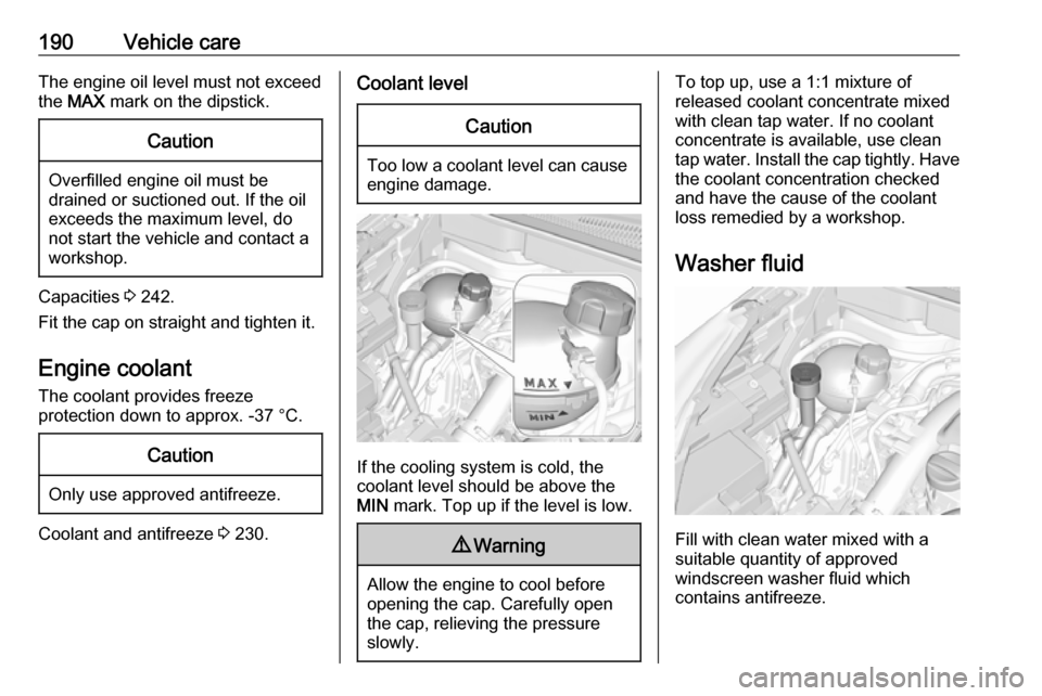
Coolant levelCaution
Too low a coolant level can cause
engine damage.
If the cooling system is cold, the
coolant level should be above the
MIN mark. Top up if the level is low.
9Warning
Allow the engine to cool before
opening the cap. Carefully open
the cap, relieving the pressure
slowly.
To top up, use a 1:1 mixture of
released coolant concentrate mixed
with clean tap water. If no coolant
concentrate is available, use clean
tap water. Install the cap tightly. Have the coolant concentration checked
and have the cause of the coolant
loss remedied by a workshop.
Washer fluid
Fill with clean water mixed with a
suitable quantity of approved
windscreen washer fluid which
contains antifreeze.