trailer VAUXHALL CROSSLAND X 2020 User Guide
[x] Cancel search | Manufacturer: VAUXHALL, Model Year: 2020, Model line: CROSSLAND X, Model: VAUXHALL CROSSLAND X 2020Pages: 245, PDF Size: 21.85 MB
Page 172 of 245

170Driving and operatingTrailer towingTrailer loadsThe permissible trailer loads are
vehicle and engine-dependent
maximum values which must not be
exceeded. The actual trailer load is
the difference between the actual
gross weight of the trailer and the
actual coupling socket load with the
trailer coupled.
The permissible trailer loads are
specified in the vehicle documents. In
general, they are valid for inclines up
to 12%.
The permissible trailer load applies
up to the specified incline and at sea
level. Since engine power decreases
as altitude increases due to the air
becoming thinner, therefore reducing
climbing ability, the permissible gross train weight also decreases by 10%
for every 1000 m of altitude. The
gross train weight does not have to be
reduced when driving on roads with
slight inclines (less than 8%, e.g.
motorways).The permissible gross train weight must not be exceeded. This weight is
specified on the identification plate
3 221.
Vertical coupling load
The vertical coupling load is the load
exerted by the trailer on the coupling
ball. It can be varied by changing the
weight distribution when loading the
trailer.
The maximum permissible vertical
coupling load of 65 kg is specified on the towing equipment identification
plate and in the vehicle documents.
For vehicles with engine DV5RC and
automatic transmission, the
maximum permissible vertical
coupling load is 55 kg. Always aim for the maximum load, especially in the
case of heavy trailers. The vertical
coupling load should never fall below
25 kg.Rear axle load
When the trailer is coupled and the
towing vehicle fully loaded, the
permissible rear axle load (see
identification plate or vehicle
documents) may be exceeded by
60 kg , the gross vehicle weight rating
must not be exceeded. If the
permissible rear axle load is
exceeded, a maximum speed of
60 mph applies.
Towing equipmentCaution
When operating without a trailer,
remove the coupling ball bar.
Stowage of coupling ball bar
The bag with the coupling ball bar is
stowed on the rear floor cover in the
load compartment.
Page 174 of 245

172Driving and operatingInserting the coupling ball bar
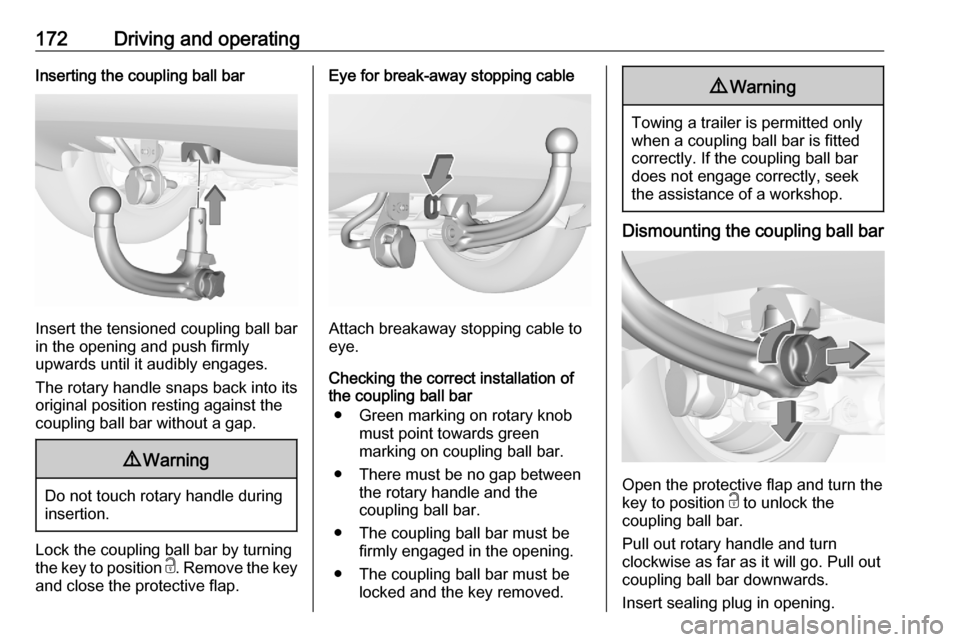
Insert the tensioned coupling ball bar
in the opening and push firmly
upwards until it audibly engages.
The rotary handle snaps back into its
original position resting against the
coupling ball bar without a gap.
9 Warning
Do not touch rotary handle during
insertion.
Lock the coupling ball bar by turning
the key to position c. Remove the key
and close the protective flap.
Eye for break-away stopping cable
Attach breakaway stopping cable to
eye.
Checking the correct installation of
the coupling ball bar
● Green marking on rotary knob must point towards green
marking on coupling ball bar.
● There must be no gap between the rotary handle and the
coupling ball bar.
● The coupling ball bar must be firmly engaged in the opening.
● The coupling ball bar must be locked and the key removed.
9Warning
Towing a trailer is permitted only
when a coupling ball bar is fitted correctly. If the coupling ball bardoes not engage correctly, seekthe assistance of a workshop.
Dismounting the coupling ball bar
Open the protective flap and turn the
key to position c to unlock the
coupling ball bar.
Pull out rotary handle and turn
clockwise as far as it will go. Pull out coupling ball bar downwards.
Insert sealing plug in opening.
Page 194 of 245

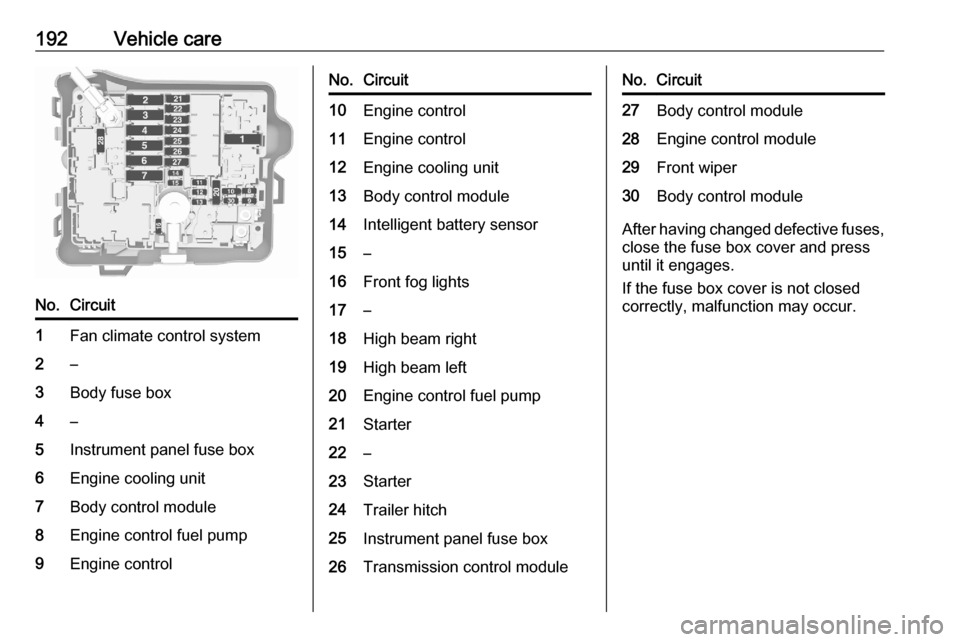
192Vehicle careNo.Circuit1Fan climate control system2–3Body fuse box4–5Instrument panel fuse box6Engine cooling unit7Body control module8Engine control fuel pump9Engine controlNo.Circuit10Engine control11Engine control12Engine cooling unit13Body control module14Intelligent battery sensor15–16Front fog lights17–18High beam right19High beam left20Engine control fuel pump21Starter22–23Starter24Trailer hitch25Instrument panel fuse box26Transmission control moduleNo.Circuit27Body control module28Engine control module29Front wiper30Body control module
After having changed defective fuses,
close the fuse box cover and press
until it engages.
If the fuse box cover is not closed
correctly, malfunction may occur.
Page 195 of 245

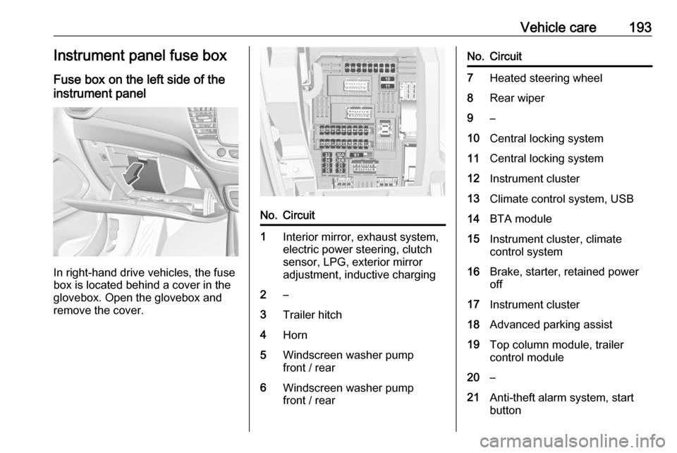
Vehicle care193Instrument panel fuse boxFuse box on the left side of the
instrument panel
In right-hand drive vehicles, the fuse
box is located behind a cover in the
glovebox. Open the glovebox and
remove the cover.
No.Circuit1Interior mirror, exhaust system,
electric power steering, clutch
sensor, LPG, exterior mirror
adjustment, inductive charging2–3Trailer hitch4Horn5Windscreen washer pump
front / rear6Windscreen washer pump
front / rearNo.Circuit7Heated steering wheel8Rear wiper9–10Central locking system11Central locking system12Instrument cluster13Climate control system, USB14BTA module15Instrument cluster, climate
control system16Brake, starter, retained power
off17Instrument cluster18Advanced parking assist19Top column module, trailer
control module20–21Anti-theft alarm system, start
button
Page 217 of 245

Service and maintenance215Service and
maintenanceGeneral information ...................215
Service information ..................215
Recommended fluids, lubricants and parts .................................... 219
Recommended fluids and lubricants ................................ 219General information
Service information In order to ensure economical and
safe vehicle operation and to
maintain the value of your vehicle, it
is of vital importance that all
maintenance work is carried out at the proper intervals as specified.
The detailed, up-to-date service
schedule for your vehicle is available
at the workshop.
Severe operating conditions exist if one or more of the following
circumstances occur frequently: Cold
starting, stop and go operation, e.g.
for taxis and police vehicles, trailer
operation, mountain driving, driving
on poor and sandy road surfaces,
increased air pollution, presence of
airborne sand and high dust content,
driving at high altitude and large
variations of temperature.Under these severe operating
conditions, certain service work may
be required more frequently than the
regular service interval indicated in
the service display. Contact a
workshop for customised service
schedules.
Service display 3 81.
Confirmations Confirmation of service is recorded inthe Service and warranty booklet.
The date and mileage is completed
with the stamp and signature of the
servicing workshop.
Make sure that the Service and
warranty booklet is completed
correctly as continuous proof of
service is essential if any warranty or
goodwill claims are to be met, and is
also a benefit when selling the
vehicle.
Page 243 of 245

241QQuickheat ................................... 118
R
Radio Frequency Identification (RFID) ..................................... 237
Radio remote control ...................21
Rain sensor .................................. 88
REACH ....................................... 232
Reading lights ............................ 107
Rear floor storage cover ..............64
Rear fog light ...............88, 106, 186
Rear seats ................................... 45
Rear view camera ...................... 162
Rear window wiper and washer ..73
Recommended fluids and lubricants ........................ 219, 223
Refuelling ................................... 167
Registered trademarks ...............233
Reverse light............................... 186
Reversing lights .........................106
Ride control systems ..................139
Roadside assistance ....................99
Roof .............................................. 38
Roof load ...................................... 67
Roof rack ..................................... 67
S Safety belts ................................... 46
Seat adjustment ....................... 7, 42
Seat belt ........................................ 8Seat belt reminder .......................82
Seat belts ..................................... 46
Seat heating ................................. 44
Seat position ................................ 41
Selective catalytic reduction .......130
Selector lever.............................. 133
Service ............................... 120, 215
Service display ............................ 81
Service information ....................215
Service vehicle soon .................... 84
Side airbag system ......................52
Side blind spot alert ..............88, 158
Sidelights .................................... 101
Side turn lights ........................... 190
Software update ......................... 232
SOS .............................................. 99
Spare wheel ............................... 204
Speed limiter......................... 88, 143
Speedometer ............................... 79
Starting and operating ................122
Starting off ................................... 16
Starting the engine ....................124
Steering ...................................... 122
Steering wheel adjustment ......9, 70
Steering wheel controls ...............70
Stop engine .................................. 84
Stop-start system........................ 126
Storage ......................................... 61
Storage compartments .................61
Sun visor lights .......................... 108Sun visors .................................... 38
Symbols ......................................... 4
System check ............................... 84
T
Tachometer ................................. 80
Tail lights ................................... 186
Three-point seat belt .................... 47
Through-loading facility ................62
Tools .......................................... 195
Tow bar....................................... 169
Towing ................................ 169, 209
Towing another vehicle .............210
Towing equipment .....................170
Towing the vehicle .....................209
Trailer hitch ................................. 169
Trailer towing ............................. 170
Transmission ............................... 16
Transmission display .................133
Tread depth ............................... 198
Trip odometer .............................. 79
Turn lights ............................ 82, 105
Tyre chains ................................ 199
Tyre deflation detection system . 197
Tyre designations ......................196
Tyre pressure ............................ 196
Tyre pressures ........................... 230
Tyre repair kit ............................. 200