reverse VAUXHALL CROSSLAND X 2020 Owner's Guide
[x] Cancel search | Manufacturer: VAUXHALL, Model Year: 2020, Model line: CROSSLAND X, Model: VAUXHALL CROSSLAND X 2020Pages: 245, PDF Size: 21.85 MB
Page 163 of 245

Driving and operating161Zoom view
The camera records the vehicle's
surroundings during the manoeuvre in order to reconstruct a view fromabove the rear of the vehicle in its
near surroundings, allowing the
vehicle to be manoeuvred around
obstacles nearby. This view is
available with auto mode or in the
view selection menu.
180° view
The 180° view facilitates reversing
out of a parking bay, making it
possible to see the approach of
vehicles, pedestrians and cyclists.
This view is not recommended for
carrying out a complete manoeuvre.
It is made up of three areas: left 1,
centre 2 and right 3. This view is
available from the view selection menu only.
Deactivation
Panoramic view system is
deactivated when:
● driving faster than 6 mph
● 7 seconds after disengaging reverse gear
● by pressing the icon q in the left
upper corner of the touch screen
● opening the tailgate
General information9 Warning
The panoramic view system does
not replace driver vision. It will not display children, pedestrians,
cyclists, crossing traffic, animals,
or any other objects outside of the camera view area, e. g. below the
bumper, or underneath the
vehicle.
Do not drive or park the vehicle
using only the panoramic view
system.
Always check the surrounding of
the vehicle before driving.
Page 164 of 245

162Driving and operatingDisplayed images may be furtheror closer than they appear. The
area displayed is limited and
objects that are close to either
edge of the bumper or under the
bumper are not displayed on the
screen.
System limitations
Caution
For optimal operation of the
system, it is important to keep the
lense of the camera in the tailgate between the number plate lightsalways clean. Rinse the lense with water and wipe with a soft cloth.
Do not clean the lense with a
steam-jet or high-pressure jet
cleaner.
The panoramic view system may not
operate properly when:
● The surrounding is dark.
● The sun or the beam of headlights is shining directly into
the camera lenses.
● During nighttime driving.
● Weather limits visibility, such as fog, rain, or snow.
● The camera lenses are blocked by snow, ice, slush, mud, dirt.
● A trailer or bike carrier is attached
to the trailer hitch.
● The vehicle had an accident.
● There are extreme temperature changes.
Rear view camera The rear view camera assists the
driver when reversing by displaying a
view of the area behind the vehicle.
The view of the camera is displayed
in the Info Display.9 Warning
The rear view camera does not
replace driver vision. Note that
objects that are outside the
camera's field of view and the
parking assist sensors, e.g. below
the bumper or underneath the
vehicle, are not displayed.
Do not reverse or park the vehicle
using only the rear view camera.
Always check the surrounding of
the vehicle before driving.
Switching on
Rear view camera is automatically
activated when reverse gear is
engaged.
Functionality
The area displayed by the camera is
limited. The distance of the image that
appears on the display differs from
the actual distance.
Page 165 of 245
Driving and operating163Guidelines
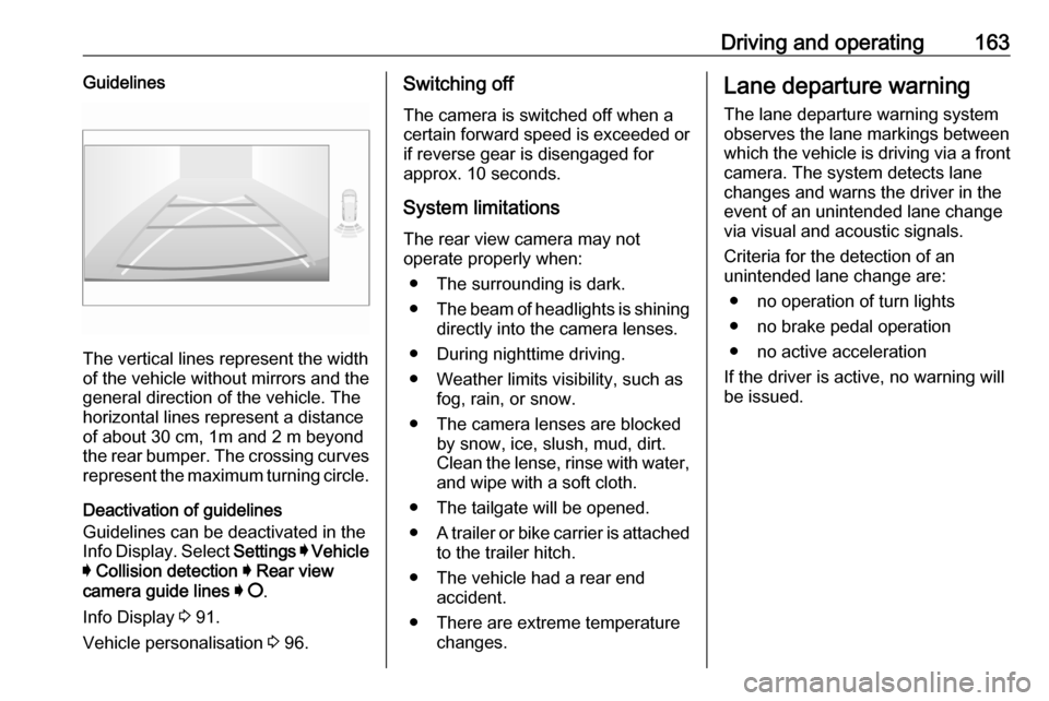
The vertical lines represent the width
of the vehicle without mirrors and the
general direction of the vehicle. The
horizontal lines represent a distance of about 30 cm, 1m and 2 m beyond
the rear bumper. The crossing curves
represent the maximum turning circle.
Deactivation of guidelines
Guidelines can be deactivated in the
Info Display. Select Settings I Vehicle
I Collision detection I Rear view
camera guide lines I § .
Info Display 3 91.
Vehicle personalisation 3 96.
Switching off
The camera is switched off when a
certain forward speed is exceeded or
if reverse gear is disengaged for
approx. 10 seconds.
System limitations
The rear view camera may not
operate properly when:
● The surrounding is dark.
● The beam of headlights is shining
directly into the camera lenses.
● During nighttime driving.
● Weather limits visibility, such as fog, rain, or snow.
● The camera lenses are blocked by snow, ice, slush, mud, dirt.Clean the lense, rinse with water,
and wipe with a soft cloth.
● The tailgate will be opened.
● A trailer or bike carrier is attached
to the trailer hitch.
● The vehicle had a rear end accident.
● There are extreme temperature changes.Lane departure warning
The lane departure warning systemobserves the lane markings between
which the vehicle is driving via a front camera. The system detects lane
changes and warns the driver in the
event of an unintended lane change
via visual and acoustic signals.
Criteria for the detection of an
unintended lane change are:
● no operation of turn lights
● no brake pedal operation
● no active acceleration
If the driver is active, no warning will
be issued.
Page 177 of 245
Vehicle care175Caution
When transporting the vehicle on
a train or on a recovery vehicle, the
mud flaps might be damaged.
Vehicle storage
Storage for a long period of time
If the vehicle is to be stored for several months:
● Wash and wax the vehicle.
● Have the wax in the engine compartment and underbody
checked.
● Clean and preserve the rubber seals.
● Fill up fuel tank completely.
● Change the engine oil.
● Drain the washer fluid reservoir.
● Check the coolant antifreeze and
corrosion protection.
● Adjust tyre pressure to the value specified for full load.
● Park the vehicle in a dry, wellventilated place. Prevent the
vehicle from rolling.
● Engage first or reverse gear or set selector lever to P.
● Do not apply the parking brake.
● Open the bonnet, close all doors and lock the vehicle.
● Disconnect the clamp from the negative terminal of the vehicle
battery. Note that all systems are
not functional, e.g. central locking system.
Anti-theft alarm system 3 31.
Putting back into operation
When the vehicle is to be put back into
operation:
● Connect the clamp to the negative terminal of the vehicle
battery. Initialize the power
windows 3 36.
● Check tyre pressure.
● Fill up the washer fluid reservoir.
● Check the engine oil level.● Check the coolant level.
● Fit the number plate if necessary.
End-of-life vehicle recovery
Information on end-of-life vehicle
recovery centres and the recycling of
end-of-life vehicles is available on our website, where legally required. Only
entrust this work to an authorised
recycling centre.
Page 191 of 245
Vehicle care189Remove the reverse light bulb
socket from the light assembly by
turning it anticlockwise.
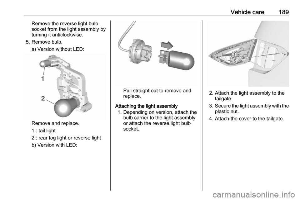
5. Remove bulb. a) Version without LED:
Remove and replace.
1 : tail light
2 : rear fog light or reverse light
b) Version with LED:
Pull straight out to remove and
replace.
Attaching the light assembly 1. Depending on version, attach the bulb carrier to the light assembly
or attach the reverse light bulb
socket.2. Attach the light assembly to the tailgate.
3. Secure the light assembly with the
plastic nut.
4. Attach the cover to the tailgate.
Page 202 of 245
200Vehicle careTyre chains are only permitted on thefront wheels.
Always use fine mesh chains that add
no more than 10 mm to the tyre tread
and the inboard sides (including chain
lock).9 Warning
Damage may lead to tyre blowout.
Tyre chains are only permitted on
tyres of size 195/65 R15 91 and
195/60 R16 89
Temporary spare wheel
The use of tyre chains is not permitted on the temporary spare wheel.
Tyre repair kit
Minor damage to the tyre tread can be
repaired with the tyre repair kit.
Do not remove foreign bodies from
the tyres.
Tyre damage exceeding 4 mm or that
is at tyre's sidewall cannot be repaired with the tyre repair kit.
9 Warning
Do not drive faster than 50 mph.
Do not use for a lengthy period.
Steering and handling may be
affected.
If you have a flat tyre:
Apply the parking brake and engage
first gear, reverse gear or P.
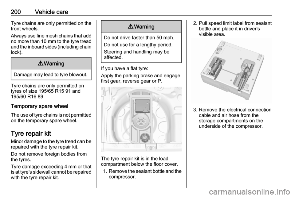
The tyre repair kit is in the load
compartment below the floor cover.
1. Remove the sealant bottle and the
compressor.
2. Pull speed limit label from sealant
bottle and place it in driver's
visible area.
3. Remove the electrical connection cable and air hose from the
storage compartments on the
underside of the compressor.
Page 205 of 245
Vehicle care203The built-in safety valve opens at a
pressure of 7 bar (102 psi).
Note the expiry date of the kit. After
this date its sealing capability is no
longer guaranteed. Pay attention to
storage information on sealant
bottle.
Replace the used sealant bottle. Dispose of the bottle as prescribed
by applicable laws.
The compressor and sealant can be
used from approx. -30 °C.
Wheel changing Make the following preparations and
observe the following information:
● Park the vehicle on a level, firm and non-skid surface. The front
wheels must be in the straight- ahead position.
● If necessary, place a chock under
the wheel diagonally opposite the wheel to be changed.
● Apply the parking brake and engage first gear, reverse gear or
P .● If the ground on which the vehicle
is standing is soft, a solid board
(max. 1 cm thick) should be
placed under the jack.
● Take heavy objects out of the vehicle before jacking up.
● No people or animals may be in the vehicle when it is jacked-up.
● Never crawl under a jacked-up vehicle.
● Do not start the vehicle when it is
raised on the jack.
● Before screwing in the wheel bolts, clean them.9Warning
Do not grease wheel bolts.
Tightening torques
Caution
If the vehicle is equipped with alloy
wheels, tighten the wheel bolts
manually at least for the first five
turns.
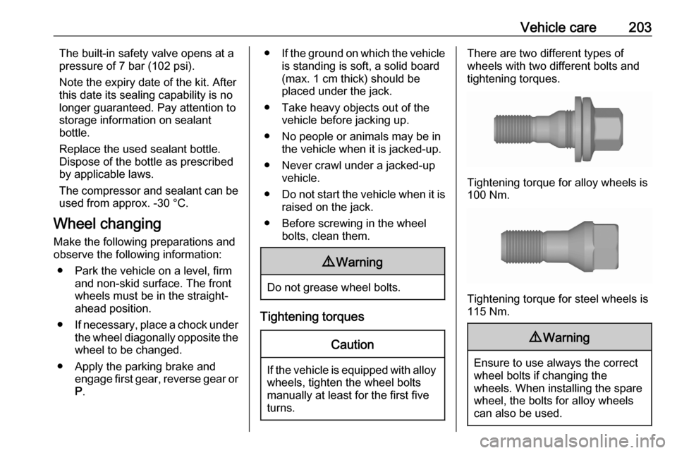
There are two different types of
wheels with two different bolts and tightening torques.
Tightening torque for alloy wheels is
100 Nm.
Tightening torque for steel wheels is
115 Nm.
9 Warning
Ensure to use always the correct
wheel bolts if changing the
wheels. When installing the spare
wheel, the bolts for alloy wheels can also be used.
Page 211 of 245

Vehicle care209● The vehicles must not come intocontact with each other during
the jump starting process.
● Apply the parking brake, transmission in neutral,
automatic transmission in P.
Open the positive terminal protection
caps of both vehicle batteries.
Lead connection order: 1. Connect the red lead to the positive terminal of the booster
battery.
2. Connect the other end of the red lead to the positive terminal of the
discharged battery.
3. Connect the black lead to the negative terminal of the boosterbattery.
4. Connect the other end of the black
lead to a vehicle grounding point
of your vehicle in the engine
compartment.
Route the leads so that they cannot
catch on rotating parts in the engine
compartment.
To start the engine: 1. Start the engine of the vehicle providing the jump.
2. After 5 minutes, start the other engine. Start attempts should be
made for no longer than
15 seconds at an interval of
1 minute.
3. Allow both engines to idle for approx. 3 minutes with the leads
connected.
4. Switch on electrical consumers (e.g. headlights, heated rear
window) of the vehicle receiving
the jump start.
5. Reverse above sequence exactly when removing leads.Towing
Towing the vehicle
Wrap a cloth around the tip of a flat
screwdriver to prevent paint damage.
Insert a screwdriver in the slot at the
bottom of the cap. Release the cap by carefully moving the screwdriver
downwards.
The towing eye is stowed with the vehicle tools 3 195.
Page 243 of 245

241QQuickheat ................................... 118
R
Radio Frequency Identification (RFID) ..................................... 237
Radio remote control ...................21
Rain sensor .................................. 88
REACH ....................................... 232
Reading lights ............................ 107
Rear floor storage cover ..............64
Rear fog light ...............88, 106, 186
Rear seats ................................... 45
Rear view camera ...................... 162
Rear window wiper and washer ..73
Recommended fluids and lubricants ........................ 219, 223
Refuelling ................................... 167
Registered trademarks ...............233
Reverse light............................... 186
Reversing lights .........................106
Ride control systems ..................139
Roadside assistance ....................99
Roof .............................................. 38
Roof load ...................................... 67
Roof rack ..................................... 67
S Safety belts ................................... 46
Seat adjustment ....................... 7, 42
Seat belt ........................................ 8Seat belt reminder .......................82
Seat belts ..................................... 46
Seat heating ................................. 44
Seat position ................................ 41
Selective catalytic reduction .......130
Selector lever.............................. 133
Service ............................... 120, 215
Service display ............................ 81
Service information ....................215
Service vehicle soon .................... 84
Side airbag system ......................52
Side blind spot alert ..............88, 158
Sidelights .................................... 101
Side turn lights ........................... 190
Software update ......................... 232
SOS .............................................. 99
Spare wheel ............................... 204
Speed limiter......................... 88, 143
Speedometer ............................... 79
Starting and operating ................122
Starting off ................................... 16
Starting the engine ....................124
Steering ...................................... 122
Steering wheel adjustment ......9, 70
Steering wheel controls ...............70
Stop engine .................................. 84
Stop-start system........................ 126
Storage ......................................... 61
Storage compartments .................61
Sun visor lights .......................... 108Sun visors .................................... 38
Symbols ......................................... 4
System check ............................... 84
T
Tachometer ................................. 80
Tail lights ................................... 186
Three-point seat belt .................... 47
Through-loading facility ................62
Tools .......................................... 195
Tow bar....................................... 169
Towing ................................ 169, 209
Towing another vehicle .............210
Towing equipment .....................170
Towing the vehicle .....................209
Trailer hitch ................................. 169
Trailer towing ............................. 170
Transmission ............................... 16
Transmission display .................133
Tread depth ............................... 198
Trip odometer .............................. 79
Turn lights ............................ 82, 105
Tyre chains ................................ 199
Tyre deflation detection system . 197
Tyre designations ......................196
Tyre pressure ............................ 196
Tyre pressures ........................... 230
Tyre repair kit ............................. 200