tow VAUXHALL CROSSLAND X 2020 Owner's Guide
[x] Cancel search | Manufacturer: VAUXHALL, Model Year: 2020, Model line: CROSSLAND X, Model: VAUXHALL CROSSLAND X 2020Pages: 245, PDF Size: 21.85 MB
Page 151 of 245

Driving and operating149Complete attention is always required
while driving, and you should be
ready to take action and apply the
brakes and / or steer the vehicle to
avoid crashes.
We recommend to deactivate the
system in the vehicle personalisation
in the following cases:
● when towing a trailer or caravan
● when carrying long objects on roof bars or a roof rack
● when the vehicle is being towed with the engine running
● when a spare wheel is fitted that is smaller than the other wheels
● before using an automatic car wash with the engine running
● before placing the vehicle on a rolling road in a workshop
● if the windscreen has been damaged close to the camera
● if the front bumper has been damaged
● if the brake lights are not working
Active emergency braking can be
deactivated in the personalisation
menu 3 96. If deactivated, milluminates in the instrument cluster
and a warning message is displayed
in the Driver Information Centre.
Fault
In case the system requires a service,
a message is displayed in the Driver
Information Centre.
If the system does not work as it
should do, vehicle messages are
displayed in the Driver Information
Centre.
Vehicle messages 3 95.
Front pedestrian protection Front pedestrian protection may help
to avoid or reduce the harm caused
by front-end crashes with pedestrians when driving forward.
The system uses the front camera in
the windscreen to detect a pedestrian
directly ahead in your path.
Front pedestrian protection can
detect and alert to pedestrians in a
forward gear at speeds between
3 mph and 37 mph.During driving in the dark, system
performance is limited.9 Danger
Front pedestrian braking does not
provide an alert or automatically
brake the vehicle, unless it detects
a pedestrian.
The system may not detect
pedestrians, including children,
when the pedestrian is not directly
ahead, not fully visible, not
standing upright, or when part of a
group.
Front pedestrian protection includes:
● detecting front pedestrian ahead● front pedestrian alert
Front pedestrian protection is
activated together with forward
collision alert.
Forward collision alert 3 145.
Detecting front pedestrian ahead
A pedestrian ahead up to a distance
of approx. 40 m is indicated by a
symbol in the instrument cluster.
Page 157 of 245

Driving and operating155
Move forwards and backwards while
observing the warnings of the parking
assist until the end of manoeuvre is
indicated. When finished, $
extinguishes in the instrument cluster.
Entry into a perpendicular parking
slot
Activation
7'' Colour Info Display: to search for a parking slot, activate the system by
selecting Park Assist on the
homepage of the touch screen. Then select Enter perpendicular parking
space .
8'' Colour Info Display: when search
for a parking slot, activate the system
by pressing Í. Select Driving
functions on the touch screen and
then Park Assist . Select Enter bay
parking space .
$ illuminates in the instrument cluster
to confirm the function.
Slow down the vehicle speed below
12 mph.
Select parking side by switching on
turn light indicator on the respective
side.
The allowed parallel distance
between the vehicle and a row of
parked cars is between 0.5 m and
1.5 m.
When several successive slots are found, the vehicle will be directed
towards the last one.
When a free slot is detected, a visual
feedback on the Colour Info Display
and an acoustic signal is given. Stop
the vehicle, select reverse gear,
release the steering wheel and start
moving without exceeding 4 mph.
Page 171 of 245

Driving and operating169To close, turn the fuel filler cap
clockwise.
Close the flap and allow it to engage.
Fuel filler cap Only use genuine fuel filler caps.Diesel-engined vehicles have special
fuel filler caps.Trailer hitch
General information
Entrust retrofitting of towing
equipment to a workshop. It may be
necessary to make changes that
affect the cooling system, heat
shields or other equipment. Only use
approved towing equipment.
The bulb outage detection function for trailer or bike carrier brake light
cannot detect a partial bulb outage.
E.g. in case of four bulbs with a power
of 5 W each, the function only detects
light outage when only a single 5 W
light remains or none remain.
LED lights are not suitable for the
wiring harness of this trailer hitch.
Towing equipment could cover the
opening of the towing eye. If this is the case use the coupling ball bar for
towing.Driving characteristics and
towing tips
Before attaching a trailer, lubricate the coupling ball. However, do not do so if a stabiliser, which acts on thecoupling ball, is being used to reduce
snaking movements.
During trailer towing do not exceed a
speed of 50 mph. A maximum speed
of 60 mph is only appropriate if an
oscillation damper is used and the
permissible gross trailer weight does
not exceed the vehicle's curb weight.
For trailers with low driving stability
and caravan trailers, the use of an
oscillation damper is strongly
recommended.
If the trailer starts snaking, drive more slowly, do not attempt to correct the
steering and brake sharply if
necessary.
When driving downhill, drive in the
same gear as if driving uphill and
drive at a similar speed.
Adjust tyre pressure to the value
specified for full load 3 229.
Page 172 of 245
170Driving and operatingTrailer towingTrailer loadsThe permissible trailer loads are
vehicle and engine-dependent
maximum values which must not be
exceeded. The actual trailer load is
the difference between the actual
gross weight of the trailer and the
actual coupling socket load with the
trailer coupled.
The permissible trailer loads are
specified in the vehicle documents. In
general, they are valid for inclines up
to 12%.
The permissible trailer load applies
up to the specified incline and at sea
level. Since engine power decreases
as altitude increases due to the air
becoming thinner, therefore reducing
climbing ability, the permissible gross train weight also decreases by 10%
for every 1000 m of altitude. The
gross train weight does not have to be
reduced when driving on roads with
slight inclines (less than 8%, e.g.
motorways).The permissible gross train weight must not be exceeded. This weight is
specified on the identification plate
3 221.
Vertical coupling load
The vertical coupling load is the load
exerted by the trailer on the coupling
ball. It can be varied by changing the
weight distribution when loading the
trailer.
The maximum permissible vertical
coupling load of 65 kg is specified on the towing equipment identification
plate and in the vehicle documents.
For vehicles with engine DV5RC and
automatic transmission, the
maximum permissible vertical
coupling load is 55 kg. Always aim for the maximum load, especially in the
case of heavy trailers. The vertical
coupling load should never fall below
25 kg.Rear axle load
When the trailer is coupled and the
towing vehicle fully loaded, the
permissible rear axle load (see
identification plate or vehicle
documents) may be exceeded by
60 kg , the gross vehicle weight rating
must not be exceeded. If the
permissible rear axle load is
exceeded, a maximum speed of
60 mph applies.
Towing equipmentCaution
When operating without a trailer,
remove the coupling ball bar.
Stowage of coupling ball bar
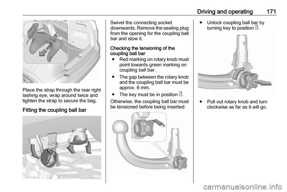
The bag with the coupling ball bar is
stowed on the rear floor cover in the
load compartment.
Page 173 of 245
Driving and operating171
Place the strap through the rear right
lashing eye, wrap around twice and
tighten the strap to secure the bag.
Fitting the coupling ball bar
Swivel the connecting socket
downwards. Remove the sealing plug from the opening for the coupling ball
bar and stow it.
Checking the tensioning of the
coupling ball bar
● Red marking on rotary knob must
point towards green marking on
coupling ball bar.
● The gap between the rotary knob
and the coupling ball bar must be approx. 6 mm.
● The key must be in position c.
Otherwise, the coupling ball bar must
be tensioned before being inserted:● Unlock coupling ball bar by
turning key to position c.
● Pull out rotary knob and turn
clockwise as far as it will go.
Page 174 of 245
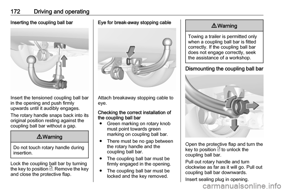
172Driving and operatingInserting the coupling ball bar
Insert the tensioned coupling ball bar
in the opening and push firmly
upwards until it audibly engages.
The rotary handle snaps back into its
original position resting against the
coupling ball bar without a gap.
9 Warning
Do not touch rotary handle during
insertion.
Lock the coupling ball bar by turning
the key to position c. Remove the key
and close the protective flap.
Eye for break-away stopping cable
Attach breakaway stopping cable to
eye.
Checking the correct installation of
the coupling ball bar
● Green marking on rotary knob must point towards green
marking on coupling ball bar.
● There must be no gap between the rotary handle and the
coupling ball bar.
● The coupling ball bar must be firmly engaged in the opening.
● The coupling ball bar must be locked and the key removed.
9Warning
Towing a trailer is permitted only
when a coupling ball bar is fitted correctly. If the coupling ball bardoes not engage correctly, seekthe assistance of a workshop.
Dismounting the coupling ball bar
Open the protective flap and turn the
key to position c to unlock the
coupling ball bar.
Pull out rotary handle and turn
clockwise as far as it will go. Pull out coupling ball bar downwards.
Insert sealing plug in opening.
Page 175 of 245

Driving and operating173Swivel the connecting socket
upwards.
Stow the coupling ball bar in the bag and secure by fixing the strap through
the rear right lashing eye. Wrap
around twice and tighten the strap to
secure the bag.
Page 176 of 245

174Vehicle careVehicle careGeneral Information...................174
Accessories and vehicle modifications .......................... 174
Vehicle storage ........................175
End-of-life vehicle recovery .....175
Vehicle checks ........................... 176
Performing work ......................176
Bonnet ..................................... 176
Engine oil ................................. 177
Engine coolant ......................... 178
Washer fluid ............................ 178
Brakes ..................................... 179
Brake fluid ............................... 179
Vehicle battery ......................... 179
Diesel fuel system bleeding .....181
Wiper blade replacement ........181
Bulb replacement .......................182
Halogen headlights ..................182
LED headlights ........................ 185
Front fog lights ......................... 185
Tail lights ................................. 186
Side turn lights ......................... 190
Number plate light ...................190
Interior lights ............................ 190Electrical system........................191
Fuses ....................................... 191
Engine compartment fuse box . 191
Instrument panel fuse box .......193
Vehicle tools .............................. 195
Tools ........................................ 195
Wheels and tyres .......................196
Winter tyres ............................. 196
Tyre designations ....................196
Tyre pressure .......................... 196
Tyre deflation detection system .................................... 197
Tread depth ............................. 198
Changing tyre and wheel size . 199
Wheel covers ........................... 199
Tyre chains .............................. 199
Tyre repair kit .......................... 200
Wheel changing .......................203
Spare wheel ............................ 204
Jump starting ............................. 208
Towing ....................................... 209
Towing the vehicle ...................209
Towing another vehicle ...........210
Appearance care .......................211
Exterior care ............................ 211
Interior care ............................. 213
Floor mats ............................... 214General Information
Accessories and vehicle modifications
We recommend the use of genuine parts and accessories and factory
approved parts specific for this
vehicle type. We cannot assess or
guarantee reliability of other products - even if they have a regulatory or
otherwise granted approval.
Any modification, conversion or other
changes made to standard vehicle
specifications (including, without
limitation, software modifications,
modifications of the electronic control units) may invalidate the warranty
offered by Vauxhall.
Furthermore, such changes may
affect driver assistance systems, may
impact fuel consumption, CO 2
emissions and other emissions of the
vehicle and cause the vehicle to no
longer conform to the operating
permit, impacting the validity of your
vehicle registration.
Page 197 of 245
Vehicle care195No.Circuit10Power outlet rear11–12–Vehicle tools
Tools
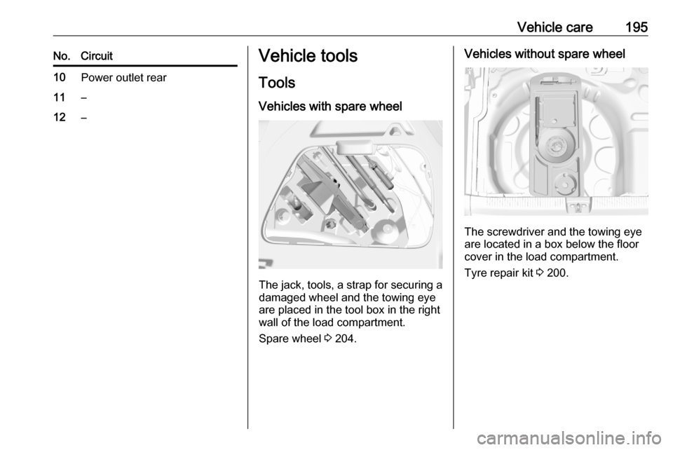
Vehicles with spare wheel
The jack, tools, a strap for securing a damaged wheel and the towing eye
are placed in the tool box in the right
wall of the load compartment.
Spare wheel 3 204.
Vehicles without spare wheel
The screwdriver and the towing eye
are located in a box below the floor
cover in the load compartment.
Tyre repair kit 3 200.
Page 204 of 245
202Vehicle careWhen the correct pressure is
obtained, switch off the
compressor.
If the prescribed tyre pressure is
not obtained within 10 minutes,
remove the tyre repair kit. Move
the vehicle one tyre rotation.
Reattach the tyre repair kit and
continue the filling procedure for
10 minutes. If the prescribed tyre
pressure is still not obtained, the
tyre is too badly damaged. Seek
the assistance of a workshop.
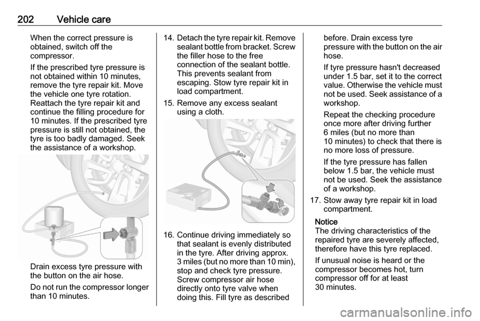
Drain excess tyre pressure with
the button on the air hose.
Do not run the compressor longer
than 10 minutes.
14. Detach the tyre repair kit. Remove
sealant bottle from bracket. Screw
the filler hose to the free connection of the sealant bottle.
This prevents sealant from
escaping. Stow tyre repair kit in
load compartment.
15. Remove any excess sealant using a cloth.
16. Continue driving immediately sothat sealant is evenly distributed
in the tyre. After driving approx.
3 miles (but no more than 10 min ),
stop and check tyre pressure.
Screw compressor air hose
directly onto tyre valve when
doing this. Fill tyre as described
before. Drain excess tyre
pressure with the button on the air
hose.
If tyre pressure hasn't decreased
under 1.5 bar, set it to the correct
value. Otherwise the vehicle must
not be used. Seek assistance of a
workshop.
Repeat the checking procedure
once more after driving further
6 miles (but no more than
10 minutes) to check that there is
no more loss of pressure.
If the tyre pressure has fallen
below 1.5 bar, the vehicle must
not be used. Seek the assistance
of a workshop.
17. Stow away tyre repair kit in load compartment.
Notice
The driving characteristics of the repaired tyre are severely affected,therefore have this tyre replaced.
If unusual noise is heard or the
compressor becomes hot, turn
compressor off for at least
30 minutes.