ECO VAUXHALL GRANDLAND X 2018 Owner's Guide
[x] Cancel search | Manufacturer: VAUXHALL, Model Year: 2018, Model line: GRANDLAND X, Model: VAUXHALL GRANDLAND X 2018Pages: 263, PDF Size: 7.41 MB
Page 63 of 263
Seats, restraints619Danger
Deactivate passenger airbag only
in combination with the use of a
child restraint system, subject to
the instructions and restrictions in
the table 3 64.
Otherwise, there is a risk of fatal
injury for a person occupying a
seat with a deactivated front
passenger airbag.
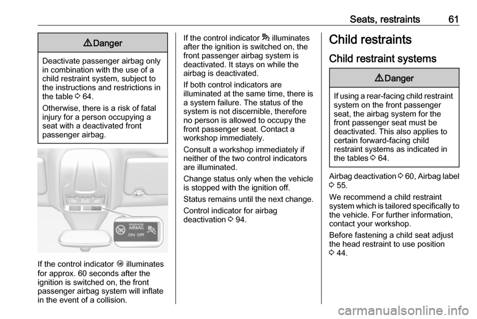
If the control indicator Ó illuminates
for approx. 60 seconds after the
ignition is switched on, the front
passenger airbag system will inflate
in the event of a collision.
If the control indicator * illuminates
after the ignition is switched on, the front passenger airbag system is
deactivated. It stays on while the
airbag is deactivated.
If both control indicators are
illuminated at the same time, there is
a system failure. The status of the
system is not discernible, therefore
no person is allowed to occupy the
front passenger seat. Contact a
workshop immediately.
Consult a workshop immediately if
neither of the two control indicators
are illuminated.
Change status only when the vehicle is stopped with the ignition off.
Status remains until the next change.
Control indicator for airbag
deactivation 3 94.Child restraints
Child restraint systems9 Danger
If using a rear-facing child restraint
system on the front passenger
seat, the airbag system for the
front passenger seat must be
deactivated. This also applies to certain forward-facing child
restraint systems as indicated in
the tables 3 64.
Airbag deactivation 3 60 , Airbag label
3 55.
We recommend a child restraint
system which is tailored specifically to
the vehicle. For further information,
contact your workshop.
Before fastening a child seat adjust
the head restraint to use position 3 44.
Page 65 of 263

Seats, restraints63In addition to the ISOFIX mounting
brackets, fasten the Top-tether strap
to the Top-tether anchors.
ISOFIX child restraint systems of
universal category positions are
marked in the table by IUF 3 64.
Selecting the right system The rear seats are the most
convenient location to fasten a child
restraint system.
Children should travel facing
rearwards in the vehicle as long as
possible. This makes sure that the
child's backbone, which is still very
weak, is under less strain in the event
of an accident.
Suitable are child restraint systems
that comply with valid UN ECE
regulations. Check local laws and
regulations for mandatory use of child restraint systems.The following child restraints are
recommended for the following
weight classes:
● Group 0, Group 0+ :
Maxi Cosi Cabriofix with or without ISOFIX base for children
up to 13 kg
● Group I : Duo Plus with ISOFIX
and Top-tether for children from 9 kg to 18 kg
● Group II, Group III : Kidfix XP with
or without ISOFIX for children
from 15 kg to 36 kg
● Group III : Graco Booster for
children from 22 kg to 36 kg
Ensure that the child restraint system to be installed is compatible with the
vehicle type.
Ensure that the mounting location of
the child restraint system within the
vehicle is correct, see following
tables.
Allow children to enter and exit the
vehicle only on the side facing away
from the traffic.
When the child restraint system is not
in use, secure the seat with a seat belt or remove it from the vehicle.Notice
Do not affix anything on the child restraint systems and do not cover
them with any other materials.
A child restraint system which has
been subjected to stress in an
accident must be replaced.
Page 77 of 263
Storage75Warning triangle
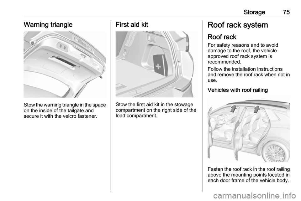
Stow the warning triangle in the space
on the inside of the tailgate and
secure it with the velcro fastener.
First aid kit
Stow the first aid kit in the stowage
compartment on the right side of the
load compartment.
Roof rack system
Roof rackFor safety reasons and to avoid
damage to the roof, the vehicle-
approved roof rack system is
recommended.
Follow the installation instructions and remove the roof rack when not in
use.
Vehicles with roof railing
Fasten the roof rack in the roof railing
above the mounting points located in
each door frame of the vehicle body.
Page 82 of 263
80Instruments and controlsThe recommended grip areas of the
steering wheel are heated quicker
and to a higher temperature than the
other areas.
Heating is operational when the
engine is running and during an
Autostop.
Stop-start system 3 139.
Horn
Press j.
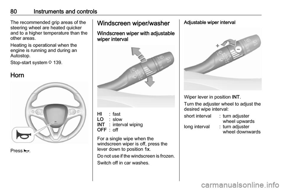
Windscreen wiper/washer
Windscreen wiper with adjustable
wiper intervalHI:fastLO:slowINT:interval wipingOFF:off
For a single wipe when the
windscreen wiper is off, press the
lever down to position 1x.
Do not use if the windscreen is frozen.
Switch off in car washes.
Adjustable wiper interval
Wiper lever in position INT.
Turn the adjuster wheel to adjust the
desired wipe interval:
short interval:turn adjuster
wheel upwardslong interval:turn adjuster
wheel downwards
Page 85 of 263
Instruments and controls839Warning
The road surface may already be
icy even though the display
indicates a few degrees above 0
°C.
Clock
Date and time are shown in the Info-
Display.
Info-Display 3 101.
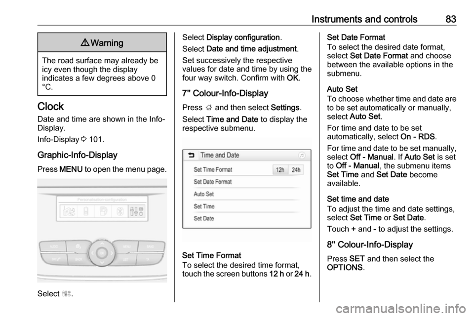
Graphic-Info-Display Press MENU to open the menu page.
Select ˆ.
Select Display configuration .
Select Date and time adjustment .
Set successively the respective
values for date and time by using the
four way switch. Confirm with OK.
7'' Colour-Info-Display
Press ; and then select Settings.
Select Time and Date to display the
respective submenu.
Set Time Format
To select the desired time format,
touch the screen buttons 12 h or 24 h .
Set Date Format
To select the desired date format,
select Set Date Format and choose
between the available options in the
submenu.
Auto Set
To choose whether time and date are
to be set automatically or manually,
select Auto Set .
For time and date to be set
automatically, select On - RDS.
For time and date to be set manually, select Off - Manual . If Auto Set is set
to Off - Manual , the submenu items
Set Time and Set Date become
available.
Set time and date
To adjust the time and date settings, select Set Time or Set Date .
Touch + and - to adjust the settings.
8'' Colour-Info-Display
Press SET and then select the
OPTIONS .
Page 88 of 263
86Instruments and controlsdevices. If applicable, seek
medical advice before using the
inductive charging device.9 Warning
Remove any metal objects from
the charging device before
charging a mobile phone, as these
objects could become very hot.
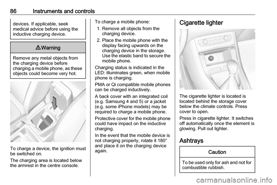
To charge a device, the ignition must
be switched on.
The charging area is located below the armrest in the centre console.
To charge a mobile phone:
1. Remove all objects from the charging device.
2. Place the mobile phone with the display facing upwards on the
charging device in the storage.
Use the elastic band to secure the
mobile phone.
Charging status is indicated in the LED: illuminates green, when mobile
phone is charging.
PMA or Qi compatible mobile phones can be charged inductively.
A back cover with an integrated coil
(e.g. Samsung 4 and 5) or a jacket
(e.g. some iPhone models) may be
required to charge a mobile phone.
Protective cover for the mobile phone
could have impact on the inductive
charging.
In the event that the mobile device is
not charging properly, rotate it 180°
and place it on the charging device
again.Cigarette lighter
The cigarette lighter is located is
located behind the storage cover
below the climate controls. Press cover to open.
Press in cigarette lighter. It switches
off automatically once the element is
glowing. Pull out lighter.
Ashtrays
Caution
To be used only for ash and not for combustible rubbish.
Page 92 of 263
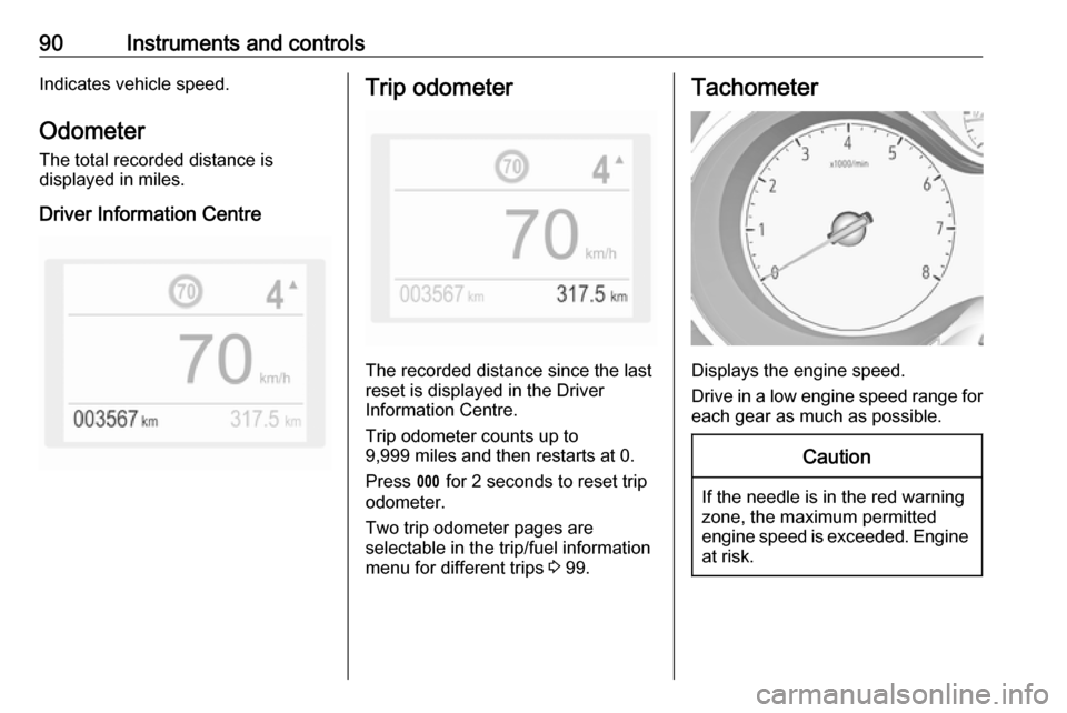
90Instruments and controlsIndicates vehicle speed.
Odometer
The total recorded distance is
displayed in miles.
Driver Information CentreTrip odometer
The recorded distance since the last
reset is displayed in the Driver
Information Centre.
Trip odometer counts up to
9,999 miles and then restarts at 0.
Press L for 2 seconds to reset trip
odometer.
Two trip odometer pages are
selectable in the trip/fuel information
menu for different trips 3 99.
Tachometer
Displays the engine speed.
Drive in a low engine speed range for each gear as much as possible.
Caution
If the needle is in the red warning
zone, the maximum permitted
engine speed is exceeded. Engine at risk.
Page 94 of 263
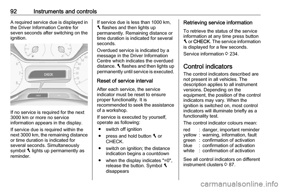
92Instruments and controlsA required service due is displayed in
the Driver Information Centre for
seven seconds after switching on the ignition.
If no service is required for the next
3000 km or more no service
information appears in the display.
If service due is required within the
next 3000 km, the remaining distance or time duration is indicated for
several seconds. Simultaneously
symbol F lights up permamently as
reminder.
If service due is less than 1000 km,
F flashes and then lights up
permanently. Remaining distance or
time duration is indicated for several
seconds.
Overdued service is indicated by a
message in the Driver Information
Centre which indicates the overdued
distance. F flashes and then lights up
permanently until service is executed.
Reset of service interval After each service, the service
indicator must be reset to ensure
proper functionality. It is
recommended to seek the assistance
of a workshop.
If service is executed by yourself,
operate as following:
● switch off ignition
● press and hold button F or
CHECK.
● switch on ignition; the distance indication begins a countdown
● when the display indicates "=0", release the button. Symbol F
disappearsRetrieving service information
To retrieve the status of the service
information at any time press button
F or CHECK . The service information
is displayed for a few seconds.
Service information 3 234.
Control indicators
The control indicators described are
not present in all vehicles. The
description applies to all instrument
versions. Depending on the
equipment, the position of the control indicators may vary. When the
ignition is switched on, most control
indicators will illuminate briefly as a
functionality test.
The control indicator colours mean:red:danger, important reminderyellow:warning, information, faultgreen:confirmation of activationblue:confirmation of activationwhite:confirmation of activation
See all control indicators on different
instrument clusters 3 87.
Page 95 of 263
Instruments and controls93Turn signal
O illuminates or flashes green.
Illuminates briefly The parking lights are switched on.
Flashes
A turn signal or the hazard warning
flashers are activated.
Rapid flashing: failure of a turn signal
light or associated fuse, failure of turn
signal light on trailer.
Bulb replacement 3 210.
Turn signals 3 118.
Seat belt reminder
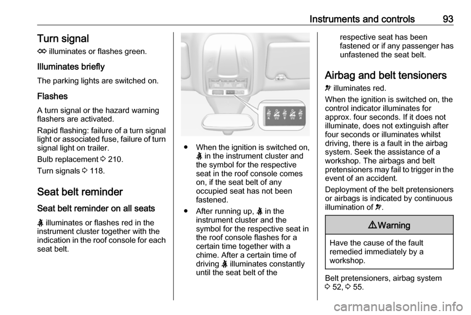
Seat belt reminder on all seats X illuminates or flashes red in the
instrument cluster together with the
indication in the roof console for each
seat belt.
● When the ignition is switched on,
X in the instrument cluster and
the symbol for the respective
seat in the roof console comes
on, if the seat belt of any
occupied seat has not been
fastened.
● After running up, X in the
instrument cluster and the
symbol for the respective seat in
the roof console flashes for a
certain time together with a
chime. After a certain time of
driving X illuminates constantly
until the seat belt of the
respective seat has been
fastened or if any passenger has
unfastened the seat belt.
Airbag and belt tensioners
v illuminates red.
When the ignition is switched on, the
control indicator illuminates for
approx. four seconds. If it does not
illuminate, does not extinguish after
four seconds or illuminates whilst
driving, there is a fault in the airbag
system. Seek the assistance of a
workshop. The airbags and belt
pretensioners may fail to trigger in the event of an accident.
Deployment of the belt pretensioners
or airbags is indicated by continuous
illumination of v.9 Warning
Have the cause of the fault
remedied immediately by a
workshop.
Belt pretensioners, airbag system
3 52, 3 55.
Page 97 of 263
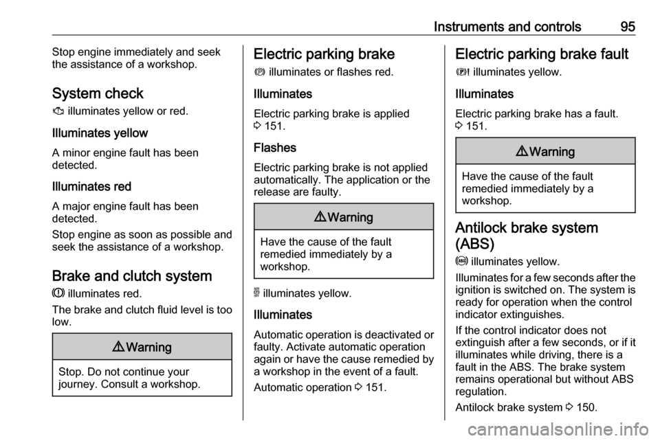
Instruments and controls95Stop engine immediately and seek
the assistance of a workshop.
System check
J illuminates yellow or red.
Illuminates yellow
A minor engine fault has been
detected.
Illuminates red A major engine fault has been
detected.
Stop engine as soon as possible and seek the assistance of a workshop.
Brake and clutch system
R illuminates red.
The brake and clutch fluid level is too
low.9 Warning
Stop. Do not continue your
journey. Consult a workshop.
Electric parking brake
m illuminates or flashes red.
Illuminates
Electric parking brake is applied
3 151.
Flashes
Electric parking brake is not applied
automatically. The application or the
release are faulty.9 Warning
Have the cause of the fault
remedied immediately by a
workshop.
o illuminates yellow.
Illuminates
Automatic operation is deactivated or
faulty. Activate automatic operation
again or have the cause remedied by a workshop in the event of a fault.
Automatic operation 3 151.
Electric parking brake fault
E illuminates yellow.
Illuminates
Electric parking brake has a fault.
3 151.9 Warning
Have the cause of the fault
remedied immediately by a
workshop.
Antilock brake system
(ABS)
u illuminates yellow.
Illuminates for a few seconds after the ignition is switched on. The system is
ready for operation when the control
indicator extinguishes.
If the control indicator does not
extinguish after a few seconds, or if it illuminates while driving, there is a
fault in the ABS. The brake system
remains operational but without ABS
regulation.
Antilock brake system 3 150.