Reverse VAUXHALL GRANDLAND X 2019 Owner's Guide
[x] Cancel search | Manufacturer: VAUXHALL, Model Year: 2019, Model line: GRANDLAND X, Model: VAUXHALL GRANDLAND X 2019Pages: 275, PDF Size: 7.63 MB
Page 188 of 275
186Driving and operatingThe panoramic view system may not
operate properly when:
● The surrounding is dark.
● The sun or the beam of headlights is shining directly into
the camera lenses.
● Weather limits visibility, such as fog, rain, or snow.
● The camera lenses are blocked by snow, ice, slush, mud, dirt.
● The vehicle is towing a trailer.
● The vehicle had an accident.
● There are extreme temperature changes.
Rear view camera
The rear view camera assists the
driver when reversing by displaying a view of the area behind the vehicle.
The view of the camera is displayed
in the Info Display.9 Warning
The rear view camera does not
replace driver vision. Note that
objects that are outside the
camera's field of view and the
parking assist sensors, e.g. below
the bumper or underneath the
vehicle, are not displayed.
Do not reverse or park the vehicle
using only the rear view camera.
Always check the surrounding of
the vehicle before driving.
Switching on
Rear view camera is automatically
activated when reverse gear is
engaged.
Functionality
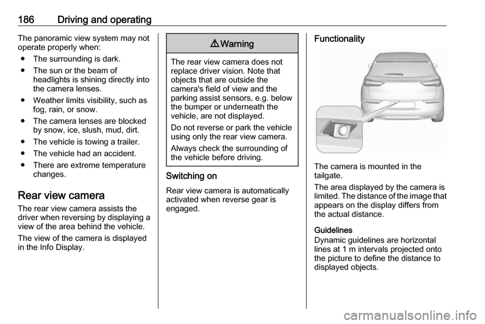
The camera is mounted in the
tailgate.
The area displayed by the camera is
limited. The distance of the image that
appears on the display differs from
the actual distance.
Guidelines
Dynamic guidelines are horizontal
lines at 1 m intervals projected onto
the picture to define the distance to displayed objects.
Page 203 of 275

Vehicle care201Caution
When transporting the vehicle on
a train or on a recovery vehicle, the
mud flaps might be damaged.
Cold protection covers
In order to prevent the accumulation
of snow at the radiator cooling fan, it is recommended to install removable
protection covers.
The protection covers must be
professionally installed, consult a
workshop.
Caution
The protection covers must be removed when one of the
following conditions occur:
● The ambient temperature is abbove 10 °C.
● When the vehicle is towed.
● The vehicle is driven at speeds
above 75 mph.
Vehicle storage
Storage for a long period of timeIf the vehicle is to be stored for several
months:
● Wash and wax the vehicle.
● Have the wax in the engine compartment and underbody
checked.
● Clean and preserve the rubber seals.
● Fill up fuel tank completely.
● Change the engine oil.
● Drain the washer fluid reservoir.
● Check the coolant antifreeze and
corrosion protection.
● Adjust tyre pressure to the value specified for full load.
● Park the vehicle in a dry, well ventilated place. Engage first or
reverse gear or set selector lever to P. Prevent the vehicle from
rolling.
● Do not apply the parking brake.● Open the bonnet, close all doors and lock the vehicle.
● Disconnect the clamp from the negative terminal of the vehicle
battery. Note that all systems are
not functional, e.g. anti-theft
alarm system.
Putting back into operation When the vehicle is to be put back into
operation:
● Connect the clamp to the negative terminal of the vehicle
battery. Initialize the power
windows 3 39.
● Check tyre pressure.
● Fill up the washer fluid reservoir.
● Check the engine oil level.
● Check the coolant level.
● Fit the number plate if necessary.
Page 214 of 275
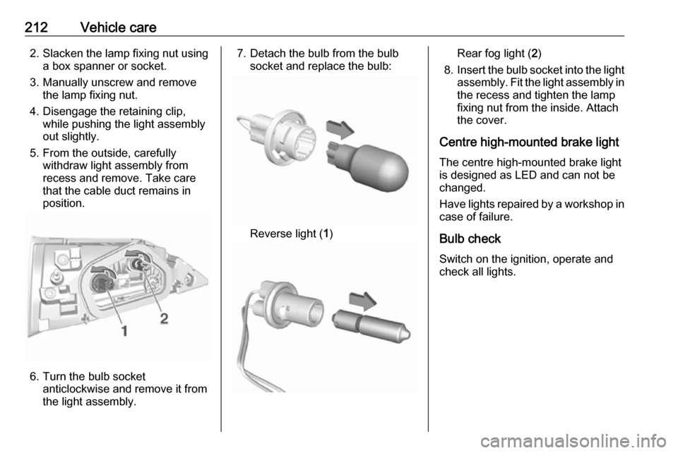
212Vehicle care2. Slacken the lamp fixing nut usinga box spanner or socket.
3. Manually unscrew and remove the lamp fixing nut.
4. Disengage the retaining clip, while pushing the light assembly
out slightly.
5. From the outside, carefully withdraw light assembly from
recess and remove. Take care
that the cable duct remains in
position.
6. Turn the bulb socket anticlockwise and remove it from
the light assembly.
7. Detach the bulb from the bulb socket and replace the bulb:
Reverse light ( 1)
Rear fog light ( 2)
8. Insert the bulb socket into the light
assembly. Fit the light assembly in the recess and tighten the lamp
fixing nut from the inside. Attach
the cover.
Centre high-mounted brake light The centre high-mounted brake light
is designed as LED and can not be
changed.
Have lights repaired by a workshop in
case of failure.
Bulb check
Switch on the ignition, operate and
check all lights.
Page 225 of 275
Vehicle care223Wheel covers
Wheel covers and tyres that are
factory approved for the respective
vehicle and comply with all of the
relevant wheel and tyre combination
requirements must be used.
If the wheel covers and tyres used are
not factory approved, the tyres must
not have a rim protection ridge.
Wheel covers must not impair brake
cooling.9 Warning
Use of unsuitable tyres or wheel
covers could lead to sudden
pressure loss and thereby
accidents.
Vehicles with steel wheels: When
using locking wheel nuts, do not
attach wheel covers.
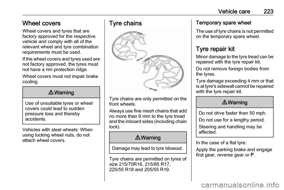
Tyre chains
Tyre chains are only permitted on the
front wheels.
Always use fine mesh chains that add no more than 9 mm to the tyre tread
and the inboard sides (including chain
lock).
9 Warning
Damage may lead to tyre blowout.
Tyre chains are permitted on tyres of
size 215/70R16, 215/65 R17,
225/55 R18 and 205/55 R19.
Temporary spare wheel
The use of tyre chains is not permitted
on the temporary spare wheel.
Tyre repair kit
Minor damage to the tyre tread can be repaired with the tyre repair kit.
Do not remove foreign bodies from
the tyres.
Tyre damage exceeding 4 mm or that
is at tyre's sidewall cannot be repaired with the tyre repair kit.9 Warning
Do not drive faster than 50 mph.
Do not use for a lengthy period.
Steering and handling may be
affected.
In the case of a flat tyre:
Apply the parking brake and engage
first gear, reverse gear or P.
Page 228 of 275
226Vehicle care
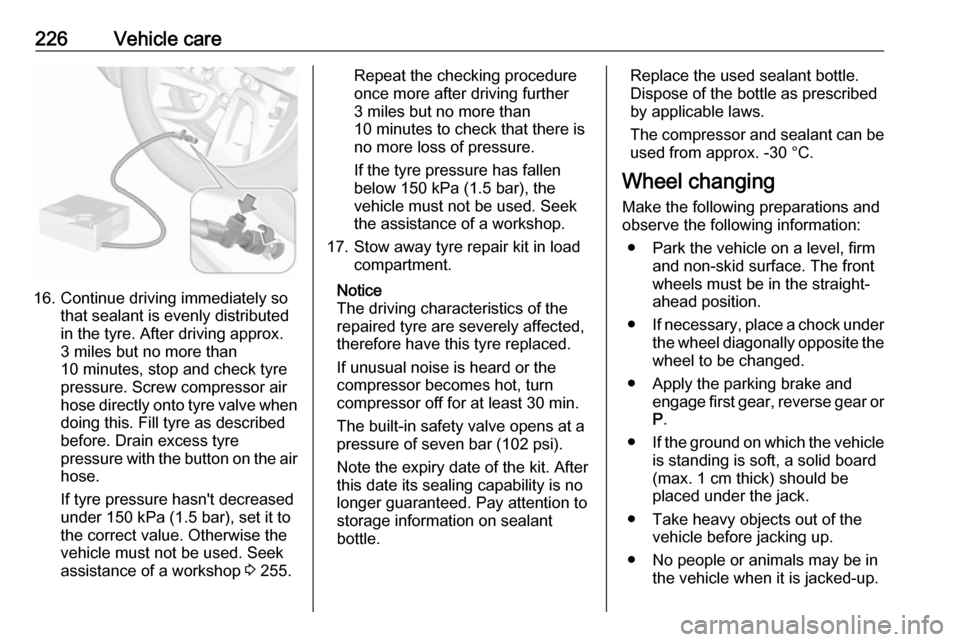
16. Continue driving immediately sothat sealant is evenly distributed
in the tyre. After driving approx.
3 miles but no more than
10 minutes, stop and check tyre
pressure. Screw compressor air
hose directly onto tyre valve when
doing this. Fill tyre as described
before. Drain excess tyre
pressure with the button on the air
hose.
If tyre pressure hasn't decreased
under 150 kPa (1.5 bar), set it to
the correct value. Otherwise the
vehicle must not be used. Seek
assistance of a workshop 3 255.
Repeat the checking procedure
once more after driving further
3 miles but no more than
10 minutes to check that there is
no more loss of pressure.
If the tyre pressure has fallen
below 150 kPa (1.5 bar), the
vehicle must not be used. Seek
the assistance of a workshop.
17. Stow away tyre repair kit in load compartment.
Notice
The driving characteristics of the repaired tyre are severely affected,
therefore have this tyre replaced.
If unusual noise is heard or the
compressor becomes hot, turn
compressor off for at least 30 min.
The built-in safety valve opens at a
pressure of seven bar (102 psi).
Note the expiry date of the kit. After
this date its sealing capability is no
longer guaranteed. Pay attention to
storage information on sealant
bottle.Replace the used sealant bottle. Dispose of the bottle as prescribed
by applicable laws.
The compressor and sealant can be used from approx. -30 °C.
Wheel changing
Make the following preparations and
observe the following information:
● Park the vehicle on a level, firm and non-skid surface. The front
wheels must be in the straight- ahead position.
● If necessary, place a chock under
the wheel diagonally opposite the
wheel to be changed.
● Apply the parking brake and engage first gear, reverse gear orP .
● If the ground on which the vehicle
is standing is soft, a solid board
(max. 1 cm thick) should be
placed under the jack.
● Take heavy objects out of the vehicle before jacking up.
● No people or animals may be in the vehicle when it is jacked-up.
Page 230 of 275
228Vehicle careFront arm position of the lifting
platform centrically under the relevant vehicle jacking point.
Spare wheel
The spare wheel can be classified as
a temporary spare wheel depending
on the size compared to the other
mounted wheels and country
regulations. In this case a permissible maximum speed applies, even
though no label at the spare wheel
indicates this.
Only mount one temporary spare
wheel. Do not drive faster than
50 mph. Take curves slowly. Do not
use for a long period of time.Caution
The use of a spare wheel that is smaller than the other wheels or in combination with winter tyres
could affect driveability. Have the defective tyre replaced as soon as
possible.
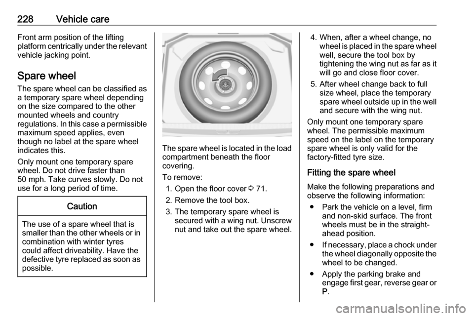
The spare wheel is located in the load
compartment beneath the floor
covering.
To remove: 1. Open the floor cover 3 71.
2. Remove the tool box.
3. The temporary spare wheel is secured with a wing nut. Unscrew
nut and take out the spare wheel.
4. When, after a wheel change, no wheel is placed in the spare wheelwell, secure the tool box by
tightening the wing nut as far as it
will go and close floor cover.
5. After wheel change back to full size wheel, place the temporary
spare wheel outside up in the well and secure with the wing nut.
Only mount one temporary spare
wheel. The permissible maximum
speed on the label on the temporary
spare wheel is only valid for the
factory-fitted tyre size.
Fitting the spare wheel
Make the following preparations and
observe the following information:
● Park the vehicle on a level, firm and non-skid surface. The front
wheels must be in the straight- ahead position.
● If necessary, place a chock under
the wheel diagonally opposite the
wheel to be changed.
● Apply the parking brake and engage first gear, reverse gear or
P .
Page 234 of 275
232Vehicle care● A discharged vehicle battery canalready freeze at a temperature
of 0 °C. Defrost the frozen battery before connecting jump leads.
● Wear eye protection and protective clothing when
handling a battery.
● Use a booster battery with the same voltage (12 V). Its capacity
(Ah) must not be much less than
that of the discharged vehicle
battery.
● Use jump leads with insulated terminals and a cross section of
at least 16 mm 2
(25 mm 2
for
diesel engines).
● Do not disconnect the discharged
vehicle battery from the vehicle.
● Switch off all unnecessary electrical consumers.
● Do not lean over the vehicle battery during jump starting.
● Do not allow the terminals of one
lead to touch those of the other
lead.● The vehicles must not come into contact with each other during
the jump starting process.
● Apply the parking brake, transmission in neutral,
automatic transmission in P.
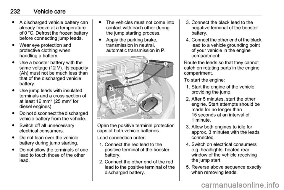
Open the positive terminal protection
caps of both vehicle batteries.
Lead connection order: 1. Connect the red lead to the positive terminal of the booster
battery.
2. Connect the other end of the red lead to the positive terminal of the
discharged battery.
3. Connect the black lead to the negative terminal of the boosterbattery.
4. Connect the other end of the black
lead to a vehicle grounding point
of your vehicle in the engine
compartment.
Route the leads so that they cannot
catch on rotating parts in the engine
compartment.
To start the engine: 1. Start the engine of the vehicle providing the jump.
2. After 5 minutes, start the other engine. Start attempts should be
made for no longer than
15 seconds at an interval of
1 minute.
3. Allow both engines to idle for approx. 3 minutes with the leads
connected.
4. Switch on electrical consumers e.g. headlights, heated rear
window of the vehicle receiving
the jump start.
5. Reverse above sequence exactly when removing leads.