ECU VAUXHALL INSIGNIA 2015.5 User Guide
[x] Cancel search | Manufacturer: VAUXHALL, Model Year: 2015.5, Model line: INSIGNIA, Model: VAUXHALL INSIGNIA 2015.5Pages: 331, PDF Size: 9.08 MB
Page 78 of 331
76Storage
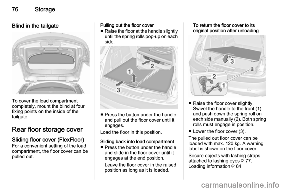
Blind in the tailgate
To cover the load compartment
completely, mount the blind at four
fixing points on the inside of the
tailgate.
Rear floor storage cover
Sliding floor cover (FlexFloor) For a convenient setting of the load
compartment, the floor cover can be
pulled out.
Pulling out the floor cover
■ Raise the floor at the handle slightly
until the spring rolls pop-up on each
side.
■ Press the button under the handle
and pull out the floor cover until it
engages.
Load the floor in this position.
Sliding back into load compartment ■ Press the button under the handle and slide in the floor cover until it
engages at the end position.
Leave the floor cover in the raised
position as long as it is loaded.
To return the floor cover to its
original position after unloading
■ Raise the floor cover slightly. Swivel the handle to the front (1)
and push down the spring roll on
each side manually (2). Both spring rolls must engage in position.
■ Lower the floor cover (3).
The pulled out floor cover can be
loaded with max. 120 kg. A warning
label is shown on the floor cover.
Secure objects with lashing straps
attached to lashing eyes 3 77.
Loading information 3 84.
Page 79 of 331
Storage779Warning
Do not load or unload the
compartment by using the sliding
floor cover when the vehicle is
parked on a slope, as the floor
cover could run uncontrolled into the end positions.
Lift the floor cover up or down only
when unloaded. Danger of injury.
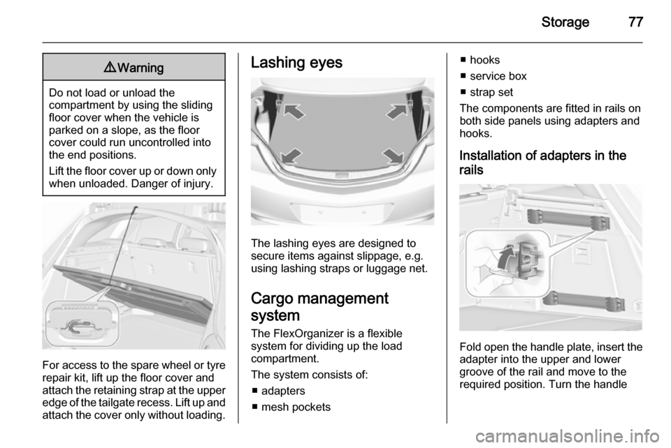
For access to the spare wheel or tyre repair kit, lift up the floor cover and
attach the retaining strap at the upper
edge of the tailgate recess. Lift up and
attach the cover only without loading.
Lashing eyes
The lashing eyes are designed to
secure items against slippage, e.g.
using lashing straps or luggage net.
Cargo management
system
The FlexOrganizer is a flexible
system for dividing up the load
compartment.
The system consists of:
■ adapters
■ mesh pockets
■ hooks
■ service box
■ strap set
The components are fitted in rails on
both side panels using adapters and
hooks.
Installation of adapters in the
rails
Fold open the handle plate, insert the adapter into the upper and lower
groove of the rail and move to the
required position. Turn the handle
Page 86 of 331
84StorageLoading information
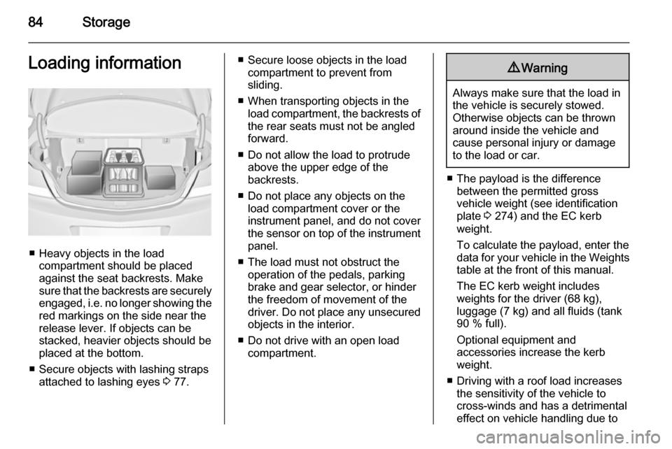
■ Heavy objects in the loadcompartment should be placedagainst the seat backrests. Make
sure that the backrests are securely engaged, i.e. no longer showing the
red markings on the side near the release lever. If objects can be
stacked, heavier objects should be
placed at the bottom.
■ Secure objects with lashing straps attached to lashing eyes 3 77.
■ Secure loose objects in the load
compartment to prevent from
sliding.
■ When transporting objects in the load compartment, the backrests of
the rear seats must not be angled
forward.
■ Do not allow the load to protrude above the upper edge of the
backrests.
■ Do not place any objects on the load compartment cover or theinstrument panel, and do not cover
the sensor on top of the instrument panel.
■ The load must not obstruct the operation of the pedals, parking
brake and gear selector, or hinder
the freedom of movement of the
driver. Do not place any unsecured objects in the interior.
■ Do not drive with an open load compartment.9 Warning
Always make sure that the load in
the vehicle is securely stowed.
Otherwise objects can be thrown
around inside the vehicle and
cause personal injury or damage
to the load or car.
■ The payload is the difference between the permitted gross
vehicle weight (see identification
plate 3 274) and the EC kerb
weight.
To calculate the payload, enter the
data for your vehicle in the Weights
table at the front of this manual.
The EC kerb weight includes
weights for the driver (68 kg),
luggage (7 kg) and all fluids (tank
90 % full).
Optional equipment and
accessories increase the kerb
weight.
■ Driving with a roof load increases the sensitivity of the vehicle to
cross-winds and has a detrimental
effect on vehicle handling due to
Page 87 of 331

Storage85
the vehicle's higher centre of
gravity. Distribute the load evenly
and secure it properly with retaining
straps. Adjust the tyre pressure and vehicle speed according to the load
conditions. Check and retighten the straps frequently.
Do not drive faster than 75 mph. The permissible roof load is
100 kg. The roof load is the
combined weight of the roof rack and the load.
Page 169 of 331

Driving and operating167
General
If a higher gear is selected when
vehicle speed is too low, or a lower
gear when vehicle speed is too high,
the shift is not executed. This can
cause a message in the Driver
Information Centre.
In manual mode, no automatic
shifting to a higher gear takes place
at high engine revolutions.
Gear shift indication
The symbol R with a number below it
is indicated when gearshifting is
recommended for fuel saving
reasons.
Shift indication appears only in
manual mode.
Electronic driving
programmes ■ Following a cold start, the operating
temperature programme increases
engine speed to quickly bring the
catalytic converter to the required
temperature.■ The automatic neutral shift function
automatically shifts to idling when
the vehicle is stopped with a
forward gear engaged and the
brake pedal is pressed.
■ When SPORT mode is engaged, the vehicle shifts at higher engine
speeds (unless cruise control is
on). SPORT mode 3 174.
■ Special programmes automatically adapt the shifting points when
driving up inclines or down hills.
■ When starting off in snowy or icy conditions or on other slippery
surfaces, the electronic
transmission control selects a
higher gear automatically.
Kickdown
If the accelerator pedal is pressed
down completely in automatic mode,
the transmission shifts to a lower gear depending on engine speed.Overheat protection
In the event of transmission-
overheating due to high outside
temperatures or sporty driving style, the torque and the maximum speed of
the engine can be temporarily
reduced.
Fault
In the event of a fault a vehicle
message is displayed in the Driver
Information Centre. Vehicle
messages 3 120.
The transmission no longer shifts
automatically. Continued travel is
possible with manual shifting.
Only the highest gear is available.
Depending on the fault, 2nd gear may also be available in manual mode.
Shift only when vehicle is stationary.
Have the cause of the fault remedied
by a workshop.
Page 184 of 331

182Driving and operating
Increase speedWith adaptive cruise control active,
hold thumb wheel turned to RES/+: speed increases continuously in large increments, or activate repeatedly
RES/+: speed increases in small
increments.
If the vehicle is driven with adaptive
cruise control active much faster than
the desired speed, e.g. after
depressing the accelerator pedal,
then the current speed can be stored
and maintained by turning the thumb
wheel to SET/-.
Reduce speed With adaptive cruise control active,
hold thumb wheel turned to SET/-:
speed decreases continuously in
large increments, or activate
repeatedly SET/-: speed decreases in
small increments.
If the vehicle is driven with adaptive
cruise control active much slower
than the desired speed, e.g. because
of a slower vehicle ahead, then thecurrent speed can be stored and
maintained by turning the thumb
wheel to SET/-.
Resume stored speed
If the system is switched on but
inactive, then turn thumb wheel to
RES/+ at a speed above 15 mph to
resume the stored speed.
Full speed range adaptivecruise control on vehicles with
automatic transmission Full speed range adaptive cruisecontrol will maintain a following gap
behind a detected vehicle and slow
your vehicle to a stop behind that
vehicle.
When the vehicle ahead drives away
within two minutes, turn thumb wheel
to RES/+ or operate the accelerator
pedal to a speed of 6 mph to resume
full speed range adaptive cruise
control.
If the stopped vehicle ahead begins to move forward and full speed range
adaptive cruise control has not
resumed, the green illuminatedvehicle ahead control indicator A will
flash and a warning chime will sound
as a reminder that the vehicle ahead
is pulling away.
When the vehicle ahead stops for
more than two minutes, the electrical
parking brake will apply automatically and the full speed range adaptive
cruise control will be deactivated. In
this event, drive the vehicle normally
by operating the accelerator pedal.
Turn thumb wheel to RES/+ at a
speed above 6 mph to resume full
speed range adaptive cruise control.9 Warning
When full speed range adaptive
cruise control is deactivated or
cancelled, the vehicle will no
longer be held at a stop and can
start to move. Always be prepared to manually apply the brake to hold the vehicle stationary.
Do not leave the vehicle while it is being held at a stop by the full
speed range adaptive cruise
control. Always move selector
Page 235 of 331
Vehicle care233
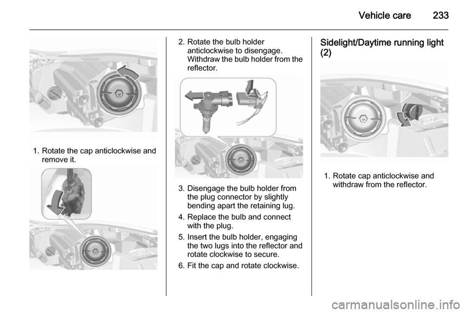
1. Rotate the cap anticlockwise andremove it.
2. Rotate the bulb holderanticlockwise to disengage.
Withdraw the bulb holder from the
reflector.
3. Disengage the bulb holder from the plug connector by slightly
bending apart the retaining lug.
4. Replace the bulb and connect with the plug.
5. Insert the bulb holder, engaging the two lugs into the reflector androtate clockwise to secure.
6. Fit the cap and rotate clockwise.
Sidelight/Daytime running light
(2)
1. Rotate cap anticlockwise and withdraw from the reflector.
Page 237 of 331

Vehicle care235Xenon headlights9Danger
Adaptive forward lighting system
uses Xenon headlights.
Xenon headlights work under
extremely high electrical voltage.
Do not touch. Have bulbs replaced by a workshop.
Bulbs for front turn signal and
corner lighting can be changed.
Sidelight/Daytime running lights are
designed as Light Emitting Diodes
(LEDs) and cannot be replaced.
Corner lighting
1. Rotate the cap anticlockwise and remove it.
2. Rotate the bulb holderanticlockwise to disengage.
Withdraw the bulb holder from the
reflector.
3. Disengage the bulb from the plug connector by unlatching and
pulling.
4. Replace the bulb and connect bulb holder with the plug
connector.
5. Insert the bulb holder, engaging the two lugs into the reflector and
rotate clockwise to secure.
6. Fit the cap and rotate clockwise.
Page 238 of 331
236Vehicle care
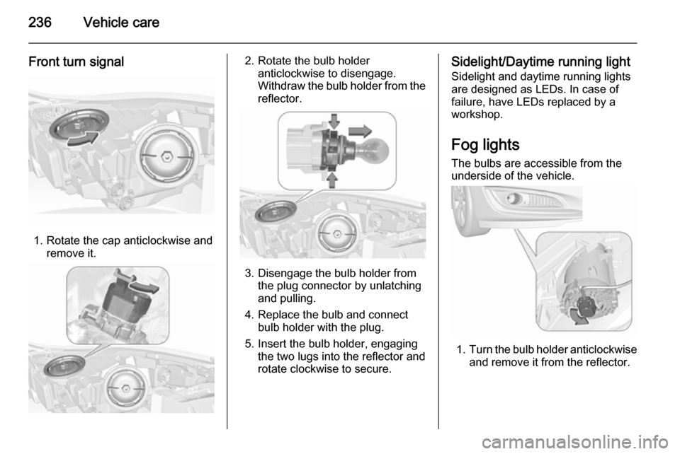
Front turn signal
1. Rotate the cap anticlockwise andremove it.
2. Rotate the bulb holderanticlockwise to disengage.
Withdraw the bulb holder from the
reflector.
3. Disengage the bulb holder from the plug connector by unlatching
and pulling.
4. Replace the bulb and connect bulb holder with the plug.
5. Insert the bulb holder, engaging the two lugs into the reflector androtate clockwise to secure.
Sidelight/Daytime running light
Sidelight and daytime running lights
are designed as LEDs. In case of
failure, have LEDs replaced by a
workshop.
Fog lights
The bulbs are accessible from the
underside of the vehicle.
1. Turn the bulb holder anticlockwise
and remove it from the reflector.
Page 239 of 331
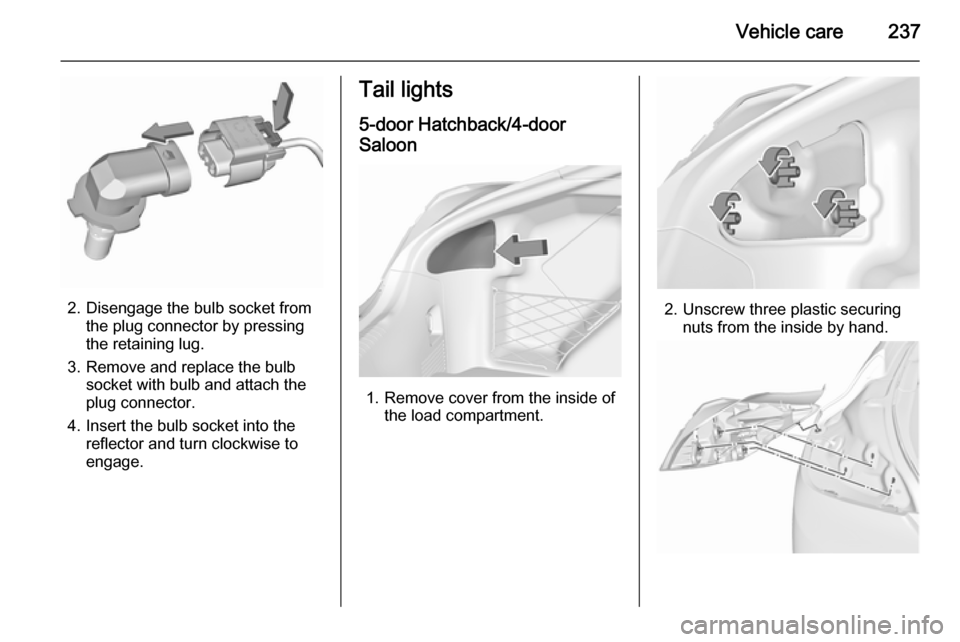
Vehicle care237
2. Disengage the bulb socket fromthe plug connector by pressing
the retaining lug.
3. Remove and replace the bulb socket with bulb and attach the
plug connector.
4. Insert the bulb socket into the reflector and turn clockwise to
engage.
Tail lights
5-door Hatchback/4-door
Saloon
1. Remove cover from the inside of the load compartment.
2. Unscrew three plastic securingnuts from the inside by hand.