wheel VAUXHALL INSIGNIA 2015.5 Repair Manual
[x] Cancel search | Manufacturer: VAUXHALL, Model Year: 2015.5, Model line: INSIGNIA, Model: VAUXHALL INSIGNIA 2015.5Pages: 331, PDF Size: 9.08 MB
Page 215 of 331

Driving and operating213
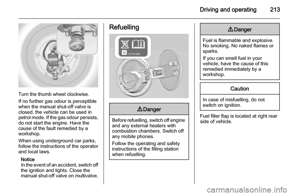
Turn the thumb wheel clockwise.
If no further gas odour is perceptible
when the manual shut-off valve is
closed, the vehicle can be used in
petrol mode. If the gas odour persists, do not start the engine. Have the
cause of the fault remedied by a workshop.
When using underground car parks,
follow the instructions of the operator
and local laws.
Notice
In the event of an accident, switch off
the ignition and lights. Close the
manual shut-off valve on multivalve.
Refuelling9 Danger
Before refuelling, switch off engine
and any external heaters with
combustion chambers. Switch off
any mobile phones.
Follow the operating and safety
instructions of the filling station
when refuelling.
9 Danger
Fuel is flammable and explosive.
No smoking. No naked flames or
sparks.
If you can smell fuel in your
vehicle, have the cause of this
remedied immediately by a
workshop.
Caution
In case of misfuelling, do not
switch on ignition.
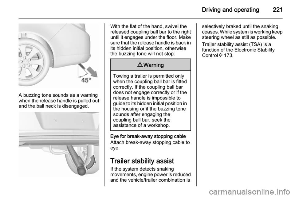
Fuel filler flap is located at right rear
side of vehicle.
Page 220 of 331

218Driving and operating
The figures are provided only for the
purpose of comparison between different vehicle variants and mustnot be taken as a guarantee for the
actual fuel consumption of a
particular vehicle. Additional
equipment may result in slightly
higher results than the stated
consumption and CO 2 figures.
Furthermore, fuel consumption is dependent on personal driving style
as well as road and traffic conditions.Trailer hitch
General information
The factory-fitted towing equipment is
folded up under the rear bumper
fascia.
Entrust retrofitting of towing
equipment to a workshop. It may be
necessary to make changes that
affect the cooling system, heat
shields or other equipment. Only use
towing equipment that has been
approved for your vehicle.
To avoid vehicle damage, the power
tailgate cannot be operated with the
radio remote control when a trailer is
electrically connected.
Fitting of towing equipment could
cover the opening of the towing eye. If this is the case use the coupling ball
bar for towing.Driving characteristics and
towing tips Before attaching a trailer, lubricate
the coupling ball. However, do not do
so if a stabiliser, which acts on the coupling ball, is being used to reduce snaking movements.
For trailers with low driving stability
and trailers with a permitted gross
vehicle weight of more than 1400 kg
(Front-wheel drive)/1600 kg (All-
wheel drive) the use of a stabiliser is
strongly recommended when driving
above 50 mph.
If the trailer starts snaking, drive more slowly, do not attempt to correct the
steering and brake sharply if
necessary.
When driving downhill, drive in the
same gear as if driving uphill and
drive at a similar speed.
Adjust tyre pressure to the value
specified for full load 3 293.
Page 223 of 331

Driving and operating221
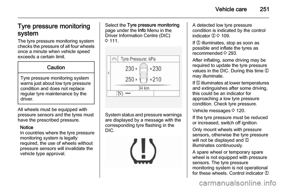
A buzzing tone sounds as a warning
when the release handle is pulled out and the ball neck is disengaged.
With the flat of the hand, swivel the
released coupling ball bar to the right
until it engages under the floor. Make sure that the release handle is back inits hidden initial position, otherwise
the buzzing tone will not stop.9 Warning
Towing a trailer is permitted only
when the coupling ball bar is fitted correctly. If the coupling ball bar
does not engage correctly or if the
release handle is impossible to guide to its hidden initial position in the housing or if the buzzing tone
sounds after engaging the
coupling ball bar, seek the
assistance of a workshop.
Eye for break-away stopping cable
Attach break-away stopping cable to
eye.
Trailer stability assist
If the system detects snaking
movements, engine power is reduced and the vehicle/trailer combination is
selectively braked until the snaking
ceases. While system is working keep
steering wheel as still as possible.
Trailer stability assist (TSA) is a
function of the Electronic Stability
Control 3 173.
Page 224 of 331

222Vehicle careVehicle careGeneral Information...................222
Vehicle checks ........................... 223
Bulb replacement .......................232
Electrical system ........................242
Vehicle tools .............................. 248
Wheels and tyres .......................249
Jump starting ............................. 262
Towing ....................................... 264
Appearance care .......................267General Information
Accessories and vehicle
modifications
We recommend to use genuine parts and accessories and factory
approved parts specific for your
vehicle type. We cannot assess or
guarantee reliability of other products
- even if they have a regulatory or
otherwise granted approval.
Do not make any modifications to the
electrical system, e.g. changes of
electronic control units (chip tuning).Caution
When transporting the vehicle on
a train or on a recovery vehicle, the
mud flaps might be damaged.
Vehicle storage
Storage for a long period of time
If the vehicle is to be stored for several months:
■ Wash and wax the vehicle.
■ Have the wax in the engine compartment and underbody
checked.
■ Clean and preserve rubber seals.
■ Fill up fuel tank completely.
■ Change engine oil.
■ Drain washer fluid reservoir.
■ Check coolant antifreeze and corrosion protection.
■ Adjust tyre pressure to the value specified for full load.
■ Park vehicle in dry, well ventilated place. Engage first or reverse gear
or set selector lever to P. Prevent
the vehicle from rolling.
■ Do not apply parking brake.
Page 249 of 331

Vehicle care247Load compartment fuse
box
The fuse box is on the left side of the
load compartment behind a cover.
Remove the cover.
No.Circuit1Central locking system/Power
tailgate2Trailer module3–4–5Trailer socket6Steering wheel heating7Selective catalytic reduction
system8Trailer socket9Sunroof10Central locking system/Tailgate11–12Selective catalytic reduction
system13–14–15Power tailgate lock
Page 250 of 331

248Vehicle care
No.Circuit16Air conditioning system17Selective catalytic reduction
system18Selective catalytic reduction
system19Side obstacle detector20Side obstacle detector/Venti‐
lated front seats21Active damping system/High
beam assist/Cruise control/
Traffic sign assistant/Lane
departure warning/Trailer
module22Anti-theft alarm system23All-wheel drive/Anti-theft alarm
system24–25–26–27–No.Circuit28–29Trailer module/Transportation
fuse30Side obstacle detector31–32–33–34Sunroof35–36–37–Vehicle tools
Tools
Vehicles with tyre repair kit
The tools and the towing eye are
located together with the tyre repair
kit in a tool box below the floor cover
in the load compartment.
Page 251 of 331

Vehicle care249
Vehicles with spare wheel
The jack with wheel wrench, the tools,
an extension bolt for securing a
damaged wheel and the towing eye
are placed in the tool box below the
spare wheel in the load compartment. Spare wheel 3 260.
Wheels and tyres
Tyre condition, wheel condition
Drive over edges slowly and at right
angles if possible. Driving over sharp
edges can cause tyre and wheel
damage. Do not trap tyres on the kerb when parking.
Regularly check the wheels for
damage. Seek the assistance of a
workshop in the event of damage or
unusual wear.
Winter tyres Winter tyres improve driving safety at
temperatures below 7 °C and should
therefore be fitted on all wheels.
In accordance with country-specific
regulations, affix the speed sticker in
the driver's field of view.
All tyre sizes are permitted as winter
tyres 3 293.
5-door Hatchback, 4-door Saloon,
Sports TourerTyre sizes 205/60 R 16 and
235/45 R 18 are only suitable as
winter tyres.
Tyre designations E.g. 215/60 R 16 95 H215=tyre width, mm60=cross-section ratio (tyre height
to tyre width), %R=belt type: RadialRF=type: RunFlat16=wheel diameter, inches95=load index e.g. 95 is equivalent
to 690 kgH=speed code letter
Speed code letter:
Q=up to 100 mphS=up to 112 mphT=up to 118 mphH=up to 130 mphV=up to 150 mphW=up to 168 mph
Page 252 of 331

250Vehicle care
Directional tyres
Directional tyres must be mounted so that they rotate in the correct
direction. The proper rotation
direction is indicated by a symbol
(e.g. an arrow) on the sidewall.
Tyre pressure
Check the pressure of cold tyres at least every 14 days and before any
long journey. Do not forget the spare
wheel. This also applies to vehicles
with tyre pressure monitoring system.
Unscrew the valve cap.
Tyre pressure 3 293.
The tyre pressure information label
on the left door frame indicates the
original equipment tyres and the
correspondent tyre pressures.
The tyre pressure data refers to cold
tyres. It applies to summer and winter tyres.
Always inflate the spare tyre to the
pressure specified for full load.
The ECO tyre pressure serves to
achieve the smallest amount of fuel
consumption possible.
Incorrect tyre pressures will impair
safety, vehicle handling, comfort and
fuel economy and will increase tyre
wear.
Tyre pressures differ depending on
various options. For the correct tyre
pressure value, follow the procedure
below:
1. Identify drive axle and body style.
2. Identify the engine identifier code.
Engine data 3 279.
3. Identify the respective tyre.
The tyre pressure tables show all
possible tyre combinations 3 293.For the tyres approved for your
vehicle, refer to the EEC Certificate of Conformity provided with your vehicle
or other national registration
documents.
The driver is responsible for correct
adjustment of tyre pressure.9 Warning
If the pressure is too low, this can
result in considerable tyre warm-
up and internal damage, leading to tread separation and even to tyre
blow-out at high speeds.
If the tyre pressure shall be reduced
or increased on a vehicle with tyre
pressure monitoring system, switch
off ignition. After adjusting tyre
pressure switch on ignition and select the according setting on the page
Tyre load in the Driver Information
Centre, 3 111.
Page 253 of 331

Vehicle care251Tyre pressure monitoring
system
The tyre pressure monitoring system
checks the pressure of all four wheels once a minute when vehicle speed
exceeds a certain limit.Caution
Tyre pressure monitoring system
warns just about low tyre pressure
condition and does not replace
regular tyre maintenance by the
driver.
All wheels must be equipped with
pressure sensors and the tyres must
have the prescribed pressure.
Notice
In countries where the tyre pressure monitoring system is legally
required, the use of wheels without
pressure sensors will invalidate the
vehicle type approval.
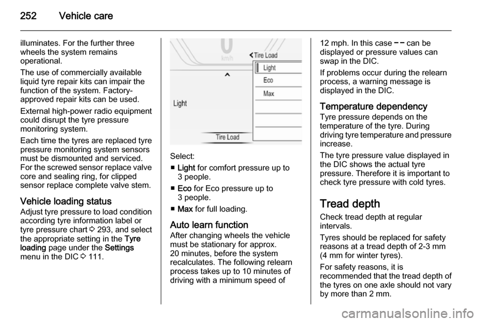
Select the Tyre pressure monitoring
page under the Info Menu in the
Driver Information Centre (DIC)
3 111.
System status and pressure warnings
are displayed by a message with the
corresponding tyre flashing in the
DIC.
A detected low tyre pressure
condition is indicated by the control
indicator w 3 109.
If w illuminates, stop as soon as
possible and inflate the tyres as
recommended 3 293.
After inflating, some driving may be
required to update the tyre pressure
values in the DIC. During this time w
may illuminate.
If w illuminates at lower temperatures
and extinguishes after some driving,
this could be an indicator for
approaching a low tyre pressure
condition. Check tyre pressure.
Vehicle messages 3 120.
If the tyre pressure must be reduced
or increased, switch off ignition.
Only mount wheels with pressure
sensors, otherwise the tyre pressure
will not be displayed and w
illuminates continuously.
A spare wheel or temporary spare
wheel is not equipped with pressure
sensors. The tyre pressure
monitoring system is not operational
for these wheels. Control indicator w
Page 254 of 331

252Vehicle care
illuminates. For the further three
wheels the system remains
operational.
The use of commercially available
liquid tyre repair kits can impair the
function of the system. Factory-
approved repair kits can be used.
External high-power radio equipment
could disrupt the tyre pressure
monitoring system.
Each time the tyres are replaced tyre
pressure monitoring system sensors
must be dismounted and serviced.
For the screwed sensor replace valve core and sealing ring, for clipped
sensor replace complete valve stem.
Vehicle loading status Adjust tyre pressure to load condition according tyre information label or
tyre pressure chart 3 293, and select
the appropriate setting in the Tyre
loading page under the Settings
menu in the DIC 3 111.
Select:
■ Light for comfort pressure up to
3 people.
■ Eco for Eco pressure up to
3 people.
■ Max for full loading.
Auto learn function
After changing wheels the vehicle
must be stationary for approx.
20 minutes, before the system
recalculates. The following relearn
process takes up to 10 minutes of
driving with a minimum speed of
12 mph. In this case $ can be
displayed or pressure values can
swap in the DIC.
If problems occur during the relearn
process, a warning message is
displayed in the DIC.
Temperature dependency
Tyre pressure depends on the
temperature of the tyre. During
driving tyre temperature and pressure increase.
The tyre pressure value displayed in
the DIC shows the actual tyre
pressure. Therefore it is important to
check tyre pressure with cold tyres.
Tread depth
Check tread depth at regular
intervals.
Tyres should be replaced for safety
reasons at a tread depth of 2-3 mm
(4 mm for winter tyres).
For safety reasons, it is
recommended that the tread depth of
the tyres on one axle should not vary
by more than 2 mm.