window VAUXHALL INSIGNIA 2018.5 Workshop Manual
[x] Cancel search | Manufacturer: VAUXHALL, Model Year: 2018.5, Model line: INSIGNIA, Model: VAUXHALL INSIGNIA 2018.5Pages: 327, PDF Size: 9.2 MB
Page 160 of 327
158Climate controlBasic settingsFollowing settings can be changed in
the Personalisation menu in the
Info-Display:
● fan speed regulation in automatic
mode.
● settings of automatic rear window
heating.
● settings of automatic windscreen
dehumidification
● settings of automatic seat heating
Vehicle personalisation 3 126.
Heated rear window and exterior
mirrors b
3 41
Heated windscreen ,
3 41.
Heated seats q
3 53.
Ventilated seats r
3 53Auxiliary heater
Air heater
Quickheat is an electric auxiliary air
heater which automatically warms up
the passenger compartment more
quickly.Air vents
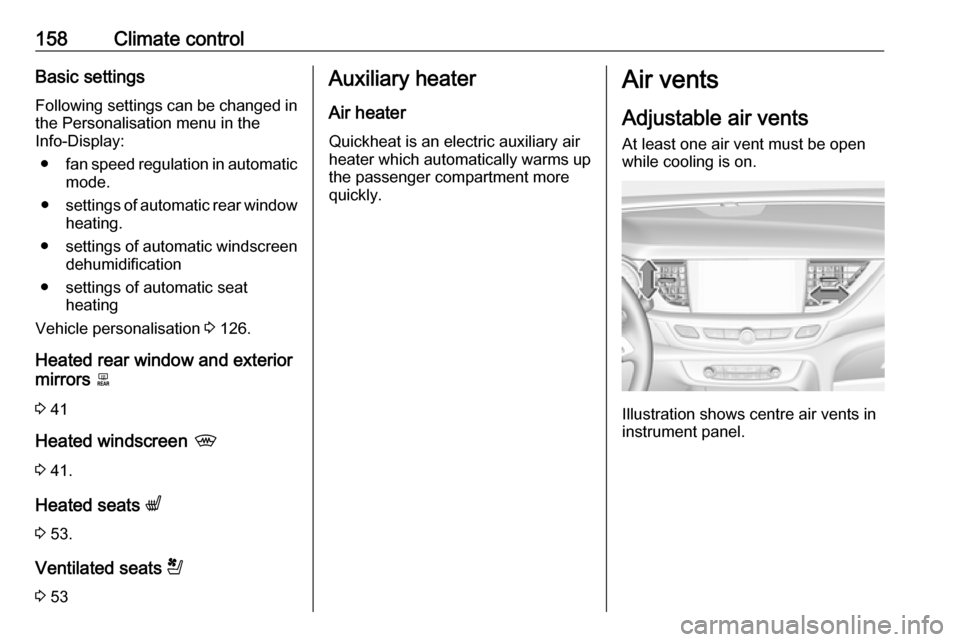
Adjustable air vents At least one air vent must be open
while cooling is on.
Illustration shows centre air vents in
instrument panel.
Page 161 of 327
Climate control159
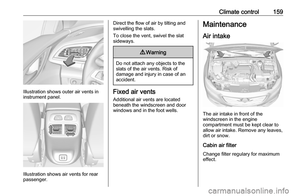
Illustration shows outer air vents in
instrument panel.
Illustration shows air vents for rear
passenger.
Direct the flow of air by tilting and
swivelling the slats.
To close the vent, swivel the slat
sideways.9 Warning
Do not attach any objects to the
slats of the air vents. Risk of
damage and injury in case of an
accident.
Fixed air vents
Additional air vents are located
beneath the windscreen and door windows and in the foot wells.
Maintenance
Air intake
The air intake in front of the
windscreen in the engine
compartment must be kept clear to
allow air intake. Remove any leaves,
dirt or snow.
Cabin air filter
Change filter regulary for maximum
effect.
Page 166 of 327
164Driving and operatingOperation on vehicles with
electronic key system in case of
failure
If either the electronic key fails or the
battery of the electronic key is weak,
the Driver Information Centre may
display No Remote Detected or
Replace Battery in Remote Key when
you try to start the vehicle.
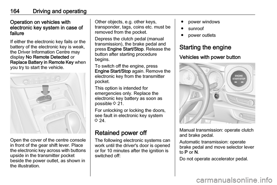
Open the cover of the centre console
in front of the gear shift lever. Place
the electronic key across with buttons
upside in the transmitter pocket
beside the power outlet, as shown in
the illustration.
Other objects, e.g. other keys,
transponder, tags, coins etc. must be removed from the pocket.
Depress the clutch pedal (manual
transmission), the brake pedal and
press Engine Start/Stop . Release the
button after starting procedure
begins.
To switch off the engine, press
Engine Start/Stop again. Remove the
electronic key from the transmitter
pocket.
This option is intended for
emergencies only. Replace the
electronic key battery as soon as
possible 3 21.
For unlocking or locking the doors,
see fault in electronic key system
3 24.
Retained power off
The following electronic systems can
work until the driver's door is opened
or for 10 minutes after the ignition is
switched off:● power windows
● sunroof
● power outlets
Starting the engine
Vehicles with power button
Manual transmission: operate clutch
and brake pedal.
Automatic transmission: operate
brake pedal and move selector lever
to P or N.
Do not operate accelerator pedal.
Page 169 of 327

Driving and operating167During an Autostop, the heating and
brake performance will be
maintained.
Conditions for an Autostop
The stop-start system checks if each
of the following conditions is fulfilled:
● The stop-start system is not manually deactivated.
● The bonnet is fully closed.
● The driver's door is closed or the driver's seat belt is fastened.
● The vehicle battery is sufficiently charged and in good condition.
● The engine is warmed up.
● The engine coolant temperature is not too high.
● The engine exhaust temperature is not too high, e.g. after driving
with high engine load.
● The ambient temperature is above -5 °C.
● The climate control system allows an Autostop.
● The brake vacuum is sufficient.● The self-cleaning function of the diesel particle filter is not active.
● The vehicle was driven at least at
walking speed since the last
Autostop.
Otherwise an Autostop will be
inhibited.
The stop-start system will be
deactivated on inclines of 12% or
more.
Certain settings of the climate control
system may inhibit an Autostop. See
Climate control chapter for more
details 3 149.
Immediately after motorway driving,
an Autostop may be inhibited.
New vehicle running-in 3 162.
Vehicle battery discharge protection
To ensure reliable engine restarts,
several battery discharge protection
features are implemented as part of
the stop-start system.
Power saving measures
During an Autostop, several electrical
features e.g. auxiliary electric heater
or heated rear window are disabled orswitched to a power saving mode.
The fan speed of the climate control
system is reduced to save power.
Restart of the engine by the driver
Vehicles with manual transmissionConventional restart
All engines have conventional restart.
Depress the clutch pedal without
depressing the brake pedal to restart
the engine.
On engines with late restart a
conventional restart is only possible
without depressed brake pedal.Late restart
All engines have late restart in
addition to conventional restart. Late
restart is only active on gradients up
to 5%.
● Depress the brake pedal.
● Depress the clutch pedal.
● Select first gear.
● Release the brake pedal to restart the engine.
Page 170 of 327

168Driving and operatingVehicles with automatic transmission
Release the brake pedal or move selector lever out of D into N or P to
restart the engine.
Restart of the engine by the stop- start system
The selector lever must be in neutral to enable an automatic restart.
If one of the following conditions
occurs during an Autostop, the
engine will be restarted automatically
by the stop-start system:
● The stop-start system is manually deactivated.
● The bonnet is opened.
● The driver's seat belt is unfastened and the driver's door
is opened.
● The engine temperature is too low.
● The charging level of the vehicle battery is below a defined level.
● The brake vacuum is not sufficient.
● The vehicle is driven at least at walking speed.● The climate control systemrequests an engine start.
● The air conditioning is manually switched on.
If the bonnet is not fully closed, a warning message is displayed in the
Driver Information Centre.
If an electrical accessory, e.g. a
portable CD player, is connected to
the power outlet, a brief power drop
during the restart might be noticeable.
Parking9 Warning
● Do not park the vehicle on an
easily ignitable surface. The
high temperature of the
exhaust system could ignite the
surface.
● Always apply the parking brake. Pull switch m for
approx. one second and check
if the control indicator m
illuminates.
The electric parking brake is applied when control indicator
m illuminates 3 108.
● Switch off the engine. ● If the vehicle is on a level surface or uphill slope, engage
first gear or set the selector
lever to position P before
switching off ignition. On an
uphill slope, turn the front
wheels away from the kerb.
If the vehicle is on a downhill
slope, engage reverse gear or
set the selector lever to position P before switching off ignition.
Turn the front wheels towards
the kerb.
● Close the windows and the sunroof.
● Switch off ignition with power button. Turn the steering wheel
until the steering wheel lock is
felt to engage.
Page 171 of 327
Driving and operating169● Lock the vehicle with button onthe door handle.
● Activate the anti-theft alarm system.
● The engine cooling fans may run
after the engine has been
switched off 3 240.Caution
After running at high engine
speeds or with high engine loads,
operate the engine briefly at a low
load or run in neutral for
approx. 30 seconds before
switching off, in order to protect
the turbocharger.
Notice
In the event of an accident with airbag deployment, the engine is
turned off automatically if the vehicle
comes to a standstill within a certain time.
Engine exhaust9 Danger
Engine exhaust gases contain
poisonous carbon monoxide,
which is colourless and odourless and could be fatal if inhaled.
If exhaust gases enter the interior
of the vehicle, open the windows.
Have the cause of the fault
rectified by a workshop.
Avoid driving with an open load
compartment, otherwise exhaust
gases could enter the vehicle.
Diesel particle filter
Automatic cleaning process
The diesel particle filter system filters
harmful soot particles out of the
exhaust gases. The system includes
a self-cleaning function that runs
automatically during driving without
any notification. The filter is cleaned
by periodically burning off the soot
particles at high temperature. This
process takes place automatically
under set driving conditions and may take up to 25 minutes. Typically it
needs between seven and twelve
minutes. Autostop is not available
and fuel consumption may be higher
during this period. The emission of
smells and smoke during this process is normal.
System requires cleaning process
Under certain driving conditions, e.g.
short distances, the system cannot
clean itself automatically.
If cleaning of the filter is required and
if previous driving conditions did not
enable automatic cleaning, it will be
Page 241 of 327

Vehicle care239Caution
When transporting the vehicle on
a train or on a recovery vehicle, the
mud flaps might be damaged.
Vehicle storage
Storage for a long period of time
If the vehicle is to be stored for several months:
● Wash and wax the vehicle.
● Have the wax in the engine compartment and underbody
checked.
● Clean and preserve the rubber seals.
● Fill up fuel tank completely.
● Change the engine oil.
● Drain the washer fluid reservoir.
● Check the coolant antifreeze and
corrosion protection.
● Adjust tyre pressure to the value specified for full load.
● Park the vehicle in a dry, wellventilated place. Engage first or
reverse gear or set selector lever
to P. Prevent the vehicle from
rolling.
● Do not apply the parking brake.
● Open the bonnet, close all doors and lock the vehicle.
● Disconnect the clamp from the negative terminal of the vehicle
battery. Beware that all systems
are not functional, e.g. anti-theft
alarm system.
Putting back into operation
When the vehicle is to be put back into
operation:
● Connect the clamp to the negative terminal of the vehicle
battery. Activate the electronics
of the power windows.
● Check tyre pressure.
● Fill up the washer fluid reservoir.
● Check the engine oil level.
● Check the coolant level.
● Fit the number plate if necessary.End-of-life vehicle recovery
Information on end-of-life vehicle
recovery centres and the recycling of
end-of-life vehicles is available on our website, where legally required. Only
entrust this work to an authorised
recycling centre.
Page 248 of 327
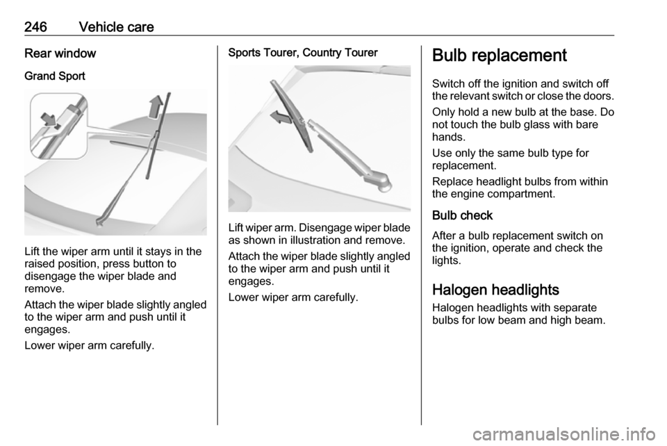
246Vehicle careRear windowGrand Sport
Lift the wiper arm until it stays in the
raised position, press button to
disengage the wiper blade and
remove.
Attach the wiper blade slightly angled
to the wiper arm and push until it
engages.
Lower wiper arm carefully.
Sports Tourer, Country Tourer
Lift wiper arm. Disengage wiper blade as shown in illustration and remove.
Attach the wiper blade slightly angled
to the wiper arm and push until it
engages.
Lower wiper arm carefully.
Bulb replacement
Switch off the ignition and switch off
the relevant switch or close the doors.
Only hold a new bulb at the base. Do not touch the bulb glass with bare
hands.
Use only the same bulb type for
replacement.
Replace headlight bulbs from within
the engine compartment.
Bulb check
After a bulb replacement switch on
the ignition, operate and check the
lights.
Halogen headlights Halogen headlights with separate
bulbs for low beam and high beam.
Page 260 of 327

258Vehicle careNo.Circuit1–2–3ABS4–5–6Tailgate7Fog light8Memory module9Heated windscreen10Seat lumbar11DC/DC battery12Heated rear window13Heated mirror14–15–16Front wiper17Power seat, passengerNo.Circuit18Sunblind19Power seat, driver20–21Sunroof22Rear wiper/Airbag23Adaptive forward lighting24–25–26Transmission control module27Ignition/Instrument panel28–29Rear view camera/Air vent30Malfunction indicator light/
Trailer31–32Camera33Seat heat front34Seat heat rearNo.Circuit35Damping/All-wheel drive36Fuel system37–38–39–40Steering wheel lock41–42–43Heated steering wheel44Headlight range adjustment45–46Engine control module47–48DC/DC converter/Air vent/E-
Boost49Rear door control module50–51–
Page 262 of 327
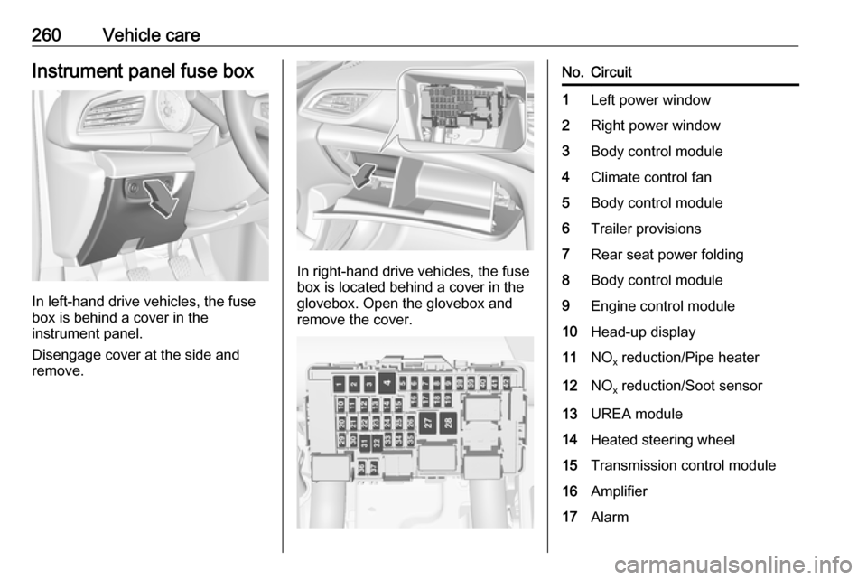
260Vehicle careInstrument panel fuse box
In left-hand drive vehicles, the fuse
box is behind a cover in the
instrument panel.
Disengage cover at the side and
remove.
In right-hand drive vehicles, the fuse
box is located behind a cover in the
glovebox. Open the glovebox and
remove the cover.
No.Circuit1Left power window2Right power window3Body control module4Climate control fan5Body control module6Trailer provisions7Rear seat power folding8Body control module9Engine control module10Head-up display11NO x reduction/Pipe heater12NO
x reduction/Soot sensor13UREA module14Heated steering wheel15Transmission control module16Amplifier17Alarm