trailer VAUXHALL INSIGNIA 2019 Owner's Guide
[x] Cancel search | Manufacturer: VAUXHALL, Model Year: 2019, Model line: INSIGNIA, Model: VAUXHALL INSIGNIA 2019Pages: 345, PDF Size: 9.61 MB
Page 251 of 345

Driving and operating249Driving characteristics and
towing tips
Before attaching a trailer, lubricate
the coupling ball. However, do not do
so if a stabiliser, which acts on the
coupling ball, is being used to reduce snaking movements.
During trailer towing do not exceed a
speed of 50 mph. A maximum speed
of 60 mph is only appropriate if an
oscillation damper is used and the
permissible gross trailer weight does
not exceed the vehicle's kerb weight.
For trailers with low driving stability
and caravan trailers, the use of an
oscillation damper is strongly
recommended.
If the trailer starts snaking, drive more slowly, do not attempt to correct the
steering and brake sharply if
necessary.
When driving downhill, drive in the
same gear as if driving uphill and
drive at a similar speed.
Adjust tyre pressure to the value
specified for full load 3 317.Trailer towing
Trailer loadsThe permissible trailer loads are
vehicle and engine-dependent
maximum values which must not be
exceeded. The actual trailer load is the difference between the actual
gross weight of the trailer and the
actual coupling socket load with the
trailer coupled.
The permissible trailer loads are
specified in the vehicle documents. In general, they are valid for gradients
up to 12%.
The permissible trailer load applies
up to the specified incline and at sea
level. Since engine power decreases
as altitude increases due to the air
becoming thinner, therefore reducing
climbing ability, the permissible gross
train weight also decreases by 10%
for every 1000 metres of altitude. The gross train weight does not have to be
reduced when driving on roads with
slight inclines (less than 8%, e.g.
motorways).The permissible gross train weight must not be exceeded. This weight is specified on the identification plate
3 302.
Vertical coupling load
The vertical coupling load is the load
exerted by the trailer on the coupling
ball. It can be varied by changing the
weight distribution when loading the
trailer.
The maximum permissible vertical
coupling load of:
● 60 kg (Grand Sport with all engines except B20DTH /
B20NFT / D20DTR)
● 75 kg (Sports Tourer, Country Tourer with all engines except
B20DTH / B20NFT / D20DTR)
● 90 kg (All bodystyles with engines B20DTH / B20NFT /
D20DTR)
is specified on the towing equipment
identification plate and in the vehicle
documents. Always aim for the
maximum load, especially in the case
of heavy trailers. The vertical coupling load should never fall below 25 kg.
Page 252 of 345

250Driving and operatingRear axle load
When the trailer is coupled and the
towing vehicle fully loaded, the
permissible rear axle load (see
identification plate or vehicle
documents) may be exceeded by
80 kg
(engines B20NFT / B20DTH /
D20DTR: 90 kg), the gross vehicle
weight rating must not be exceeded.
If the permissible rear axle load is
exceeded, a maximum speed of
60 mph applies.
Towing equipmentCaution
The folding coupling ball bar
cannot be removed from the
vehicle. When driving without a
trailer, fold in the coupling ball bar.
9 Warning
Make sure that no one is in the
pivot zone of the coupling ball bar. Risk of body injury.
When releasing the stowed
coupling ball bar, make sure to
stand left of the grip.
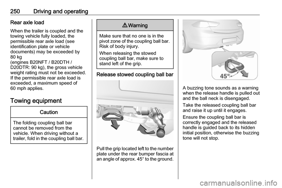
Release stowed coupling ball bar
Pull the grip located left to the number
plate under the rear bumper fascia at an angle of approx. 45° to the ground.
A buzzing tone sounds as a warning
when the release handle is pulled out and the ball neck is disengaged.
Take the released coupling ball bar
and raise it up until it engages.
Ensure the coupling ball bar is
correctly engaged and the released
handle is guided back to its hidden
initial position, otherwise the buzzing tone will not stop.
Page 253 of 345

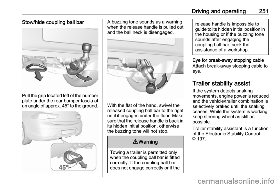
Driving and operating251Stow/hide coupling ball bar
Pull the grip located left of the number
plate under the rear bumper fascia at an angle of approx. 45° to the ground.
A buzzing tone sounds as a warning
when the release handle is pulled out and the ball neck is disengaged.
With the flat of the hand, swivel the
released coupling ball bar to the right
until it engages under the floor. Make sure that the release handle is back inits hidden initial position, otherwise
the buzzing tone will not stop.
9 Warning
Towing a trailer is permitted only
when the coupling ball bar is fitted correctly. If the coupling ball bar
does not engage correctly or if the
release handle is impossible to guide to its hidden initial position in the housing or if the buzzing tone
sounds after engaging the
coupling ball bar, seek the
assistance of a workshop.
Eye for break-away stopping cable
Attach break-away stopping cable to
eye.
Trailer stability assist
If the system detects snaking
movements, engine power is reduced
and the vehicle/trailer combination is
selectively braked until the snaking ceases. While the system is working
keep steering wheel as still as
possible.
Trailer stability assistant is a function
of the Electronic Stability Control
3 197.
Page 274 of 345

272Vehicle careNo.Circuit1–2–3ABS4–5–6Tailgate7Fog light8Memory module9Heated windscreen10Seat lumbar11DC/DC battery12Heated rear window13Heated mirror14–15–16Front wiper17Power seat, passengerNo.Circuit18Sunblind19Power seat, driver20–21Sunroof22Rear wiper/Airbag23Adaptive forward lighting24–25–26Transmission control module27Ignition/Instrument panel28–29Rear view camera/Air vent30Malfunction indicator light/
Trailer31–32Camera33Seat heat front34Seat heat rearNo.Circuit35Damping/All-wheel drive36Fuel system37–38–39–40Steering wheel lock41–42–43Heated steering wheel44Headlight range adjustment45–46Engine control module47–48DC/DC converter/Air vent/E-
Boost49Rear door control module50–51–
Page 276 of 345

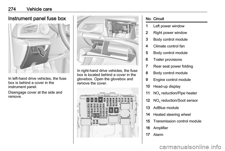
274Vehicle careInstrument panel fuse box
In left-hand drive vehicles, the fuse
box is behind a cover in the
instrument panel.
Disengage cover at the side and
remove.
In right-hand drive vehicles, the fuse
box is located behind a cover in the
glovebox. Open the glovebox and
remove the cover.
No.Circuit1Left power window2Right power window3Body control module4Climate control fan5Body control module6Trailer provisions7Rear seat power folding8Body control module9Engine control module10Head-up display11NO x reduction/Pipe heater12NO
x reduction/Soot sensor13AdBlue module14Heated steering wheel15Transmission control module16Amplifier17Alarm
Page 301 of 345

Service and maintenance299Service and
maintenanceGeneral information ...................299
Service information ..................299
Recommended fluids, lubricants and parts .................................... 300
Recommended fluids and lubricants ................................ 300General information
Service information In order to ensure economical and
safe vehicle operation and to
maintain the value of your vehicle, it
is of vital importance that all
maintenance work is carried out at the proper intervals as specified.
The detailed, up-to-date service
schedule for your vehicle is available
at the workshop.
Service display 3 103.
European service intervals Maintenance of your vehicle is
required every 20,000 miles or after
one year, whichever occurs first. Additional engine oil and filter change
is indicated by the engine oil life
system, when required earlier than
maintenance.
A shorter service interval can be valid for severe driving behaviour, e.g. for
taxis and police vehicles.
The European service intervals are
valid for the following countries:Andorra, Austria, Belgium, Bosnia-
Herzegovina, Bulgaria, Croatia,
Cyprus, Czech Republic, Denmark,
Estonia, Finland, France, Germany,
Greece, Greenland, Hungary,
Iceland, Ireland, Italy, Latvia,
Liechtenstein, Lithuania,
Luxembourg, Macedonia, Malta,
Monaco, Montenegro, Netherlands,
Norway, Poland, Portugal, Romania,
San Marino, Serbia, Slovakia,
Slovenia, Spain, Sweden,
Switzerland, United Kingdom.
Service display 3 103.
International service intervals
Maintenance of your vehicle is
required every 10,000 miles or after
1 year , whichever occurs first, unless
otherwise indicated in the service
display.
Severe operating conditions exist if
one or more of the following
circumstances occur frequently: Cold starting, stop and go operation, trailer
operation, mountain driving, driving
on poor and sandy road surfaces,
increased air pollution, presence of
airborne sand and high dust content,
Page 342 of 345

340Speech recognition.....................157
Speed limiter....................... 110, 202
Speedometer ............................. 100
Starting and operating ................176
Starting off ................................... 17
Starting the engine ....................178
Steering ...................................... 176
Steering wheel adjustment ......9, 87
Steering wheel controls .......87, 144
Stop-start system........................ 180
Storage ......................................... 72
Storage compartments .................72
Sunglasses storage .....................73
Sunroof ........................................ 42
Sunvisor lights ........................... 141
Sun visors .................................... 42
Symbols ......................................... 4
System settings .......................... 148
T
Tachometer ............................... 102
Tail lights ................................... 264
Three-point seat belt .................... 56
Tools .......................................... 275
Tow bar....................................... 248
Towing ................................ 248, 293
Towing another vehicle .............294
Towing equipment .....................250
Towing hitch installation dimensions ............................. 322Towing the vehicle .....................293
Traction Control system ............. 196
Traction Control system off......... 108
Traffic programme ......................152
Traffic sign assistant ...........110, 238
Trailer coupling ........................... 248
Trailer stability assist .................251
Trailer towing ............................. 249
Transmission ............................... 16
Tread depth ............................... 281
Trip odometer ............................ 101
Turn lights .......................... 104, 138
Tyre chains ................................ 282
Tyre designations ......................277
Tyre pressure ............................ 277
Tyre pressure monitoring system ............................. 108, 278
Tyre pressures ........................... 317
Tyre repair kit ............................. 282
U
Upholstery .................................. 297
Uplevel display ........................... 111
Usage ......................................... 159
USB port ............................... 92, 152
User profiles ............................... 151
Using smartphone applications ..162
Using this manual ..........................3V
Valet mode ................................. 117
Vehicle battery ........................... 258
Vehicle checks............................ 254
Vehicle data ................................ 304
Vehicle data recording and privacy ..................................... 331
Vehicle detected ahead ..............110
Vehicle dimensions .................... 315
Vehicle Identification Number ....302
Vehicle jack ................................ 275
Vehicle messages .....................122
Vehicle personalisation .............123
Vehicle security ............................ 33
Vehicle specific data ......................3
Vehicle storage ........................... 253
Vehicle tools ............................... 275
Vehicle unlocking ........................... 6 Vehicle weight ........................... 312
Ventilating ..................................... 53
Voice pass-thru application 157, 159
Voice prompts............................. 159
Voice recognition ........................157
W
Warning chimes .........................122
Warning lights ............................. 100
Warning triangle .......................... 82
Washer and wiper systems .........13
Washer fluid ............................... 257