ignition VAUXHALL INSIGNIA 2020 Owner's Guide
[x] Cancel search | Manufacturer: VAUXHALL, Model Year: 2020, Model line: INSIGNIA, Model: VAUXHALL INSIGNIA 2020Pages: 313, PDF Size: 9.32 MB
Page 64 of 313
62Seats, restraints9Warning
Optimum protection is only
provided when the seat is in the
proper position.
Seat position 3 47.
Keep the area in which the airbag
inflates clear of obstructions.
Fit the seat belt correctly and
engage securely. Only then is the
airbag able to protect.
Side airbag system
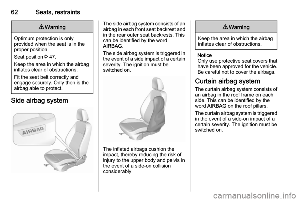
The side airbag system consists of an
airbag in each front seat backrest and in the rear outer seat backrests. This
can be identified by the word
AIRBAG .
The side airbag system is triggered in
the event of a side impact of a certain severity. The ignition must be
switched on.
The inflated airbags cushion the
impact, thereby reducing the risk of
injury to the upper body and pelvis in
the event of a side-on collision
considerably.
9 Warning
Keep the area in which the airbag
inflates clear of obstructions.
Notice
Only use protective seat covers that have been approved for the vehicle.Be careful not to cover the airbags.
Curtain airbag system
The curtain airbag system consists of an airbag in the roof frame on each
side. This can be identified by the
word AIRBAG on the roof pillars.
The curtain airbag system is triggered
in the event of a side-on impact of a
certain severity. The ignition must be
switched on.
Page 65 of 313
Seats, restraints63
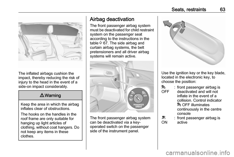
The inflated airbags cushion the
impact, thereby reducing the risk of
injury to the head in the event of a
side-on impact considerably.
9 Warning
Keep the area in which the airbag
inflates clear of obstructions.
The hooks on the handles in the
roof frame are only suitable for
hanging up light articles of
clothing, without coat hangers. Do not keep any items in these
clothes.
Airbag deactivation
The front passenger airbag system must be deactivated for child restraint
system on the passenger seat
according to the instructions in the
table 3 67. The side airbag and
curtain airbag systems, the belt
pretensioners and all driver airbag
systems will remain active.
The front passenger airbag system
can be deactivated via a key-
operated switch on the passenger side of the instrument panel.
Use the ignition key or the key blade, located in the electronic key, to
choose the position:
*
OFF:front passenger airbag is
deactivated and will not
inflate in the event of a
collision. Control indicator
* OFF illuminates
continuously in the centre
consoleV
ON:front passenger airbag is
active
Page 66 of 313

64Seats, restraints9Danger
Deactivate passenger airbag only
in combination with the use of a
child restraint system, subject to
the instructions and restrictions in
the table 3 67.
Otherwise, there is a risk of fatal
injury for a person occupying a
seat with a deactivated front
passenger airbag.
If the control indicator V illuminates
for approx. 60 seconds after the
ignition is switched on, the front
passenger airbag system will inflate
in the event of a collision.
If the control indicator * illuminates
after the ignition is switched on, the front passenger airbag system is
deactivated. It stays on while the
airbag is deactivated.
If both control indicators are
illuminated at the same time, there is
a system failure. The status of the
system is not discernible, therefore
no person is allowed to occupy the
front passenger seat. Contact a
workshop immediately.
Consult a workshop immediately if
neither of the two control indicators
are illuminated.
Change status only when the vehicle is stopped with the ignition off.
Status remains until the next change.
Control indicator for airbag
deactivation 3 105.Child restraints
Child restraint systems9 Danger
If using a rear-facing child restraint
system on the front passenger
seat, the airbag system for the
front passenger seat must be
deactivated. This also applies to certain forward-facing child
restraint systems as indicated in
the tables 3 67.
Airbag deactivation 3 63.
Airbag label 3 58.
We recommend a child restraint system which is tailored specifically to the vehicle. For further information,
contact your workshop.
When a child restraint system is being
used, pay attention to the following
usage and installation instructions
and also those supplied with the child
restraint system.
Page 95 of 313

Instruments and controls93Auto Set
To choose whether time and date are
to be set automatically or manually,
select Auto Set .
For time and date to be set
automatically, select On - RDS.
For time and date to be set manually, select Off - Manual . If Auto Set is set
to Off - Manual , the submenu items
Set Time and Set Date become
available.
Set time and date
To adjust the time and date settings, select Set Time or Set Date .
Touch + and - to adjust the settings.
Multimedia / Multimedia Navi Pro
Press ! and select Settings.
Select Time/Date .
Time zone, time and date are
provided automatically by default.
All values can be set manually, as
well. Therefore, the automatic set
functions have to be deactivated by
toggeling switch icons beside
Automatic Time and Date and
Automatic Time Zone to "O".Set time or date
Select Set Time or Set Date to enter
the respective submenu. Adjust
values by touching n or o.
Press O to leave the submenu and
store the new value. Press "x" to
leave without storing.
Set time zone
Select Select Time Zone to enter the
respective submenu. Browse through list by touching n or o. Select
desired time zone by touching list entry.
Press O to leave the submenu and
store the new value. Press "x" to
leave without storing.
Set time format
By default, the time is displayed in 24-
hour format. To set 12-hour format,
toggle switch icon beside 24-hour
Format to "O".Power outlets
A 12 V power outlet is located in the
centre console. With ignition off, this
power outlet is deactivated.
Page 96 of 313
94Instruments and controlsSports Tourer, Country Tourer: A
12 V power outlet is located at the left sidewall in the load compartment.
With ignition off, this power outlet remains active.
Do not exceed the maximum power
consumption of 120 W.
Electrical accessories that are
connected must comply with the
electromagnetic compatibility
requirements laid down in
DIN VDE 40 839.
Do not connect any current-delivering
accessories, e.g. electrical charging
devices or batteries.
Do not damage the outlets by using
unsuitable plugs.
Stop-start system 3 156.USB port
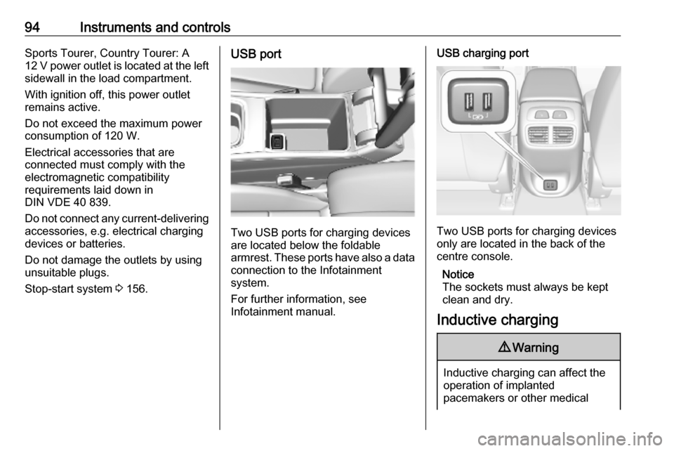
Two USB ports for charging devices
are located below the foldable
armrest. These ports have also a data connection to the Infotainment
system.
For further information, see
Infotainment manual.
USB charging port
Two USB ports for charging devices
only are located in the back of the
centre console.
Notice
The sockets must always be kept clean and dry.
Inductive charging
9 Warning
Inductive charging can affect the
operation of implanted
pacemakers or other medical
Page 97 of 313

Instruments and controls95devices. If applicable, seek
medical advice before using the
inductive charging device.9 Warning
Remove any metal objects from
the charging device before
charging a mobile device, as these objects could become very hot.
To charge a device, the ignition must
be switched on.
The charging slot is located below the
front armrest.
To charge a mobile device:
1. Remove all objects from the charging slot otherwise the
system may not charge.
2. Insert the mobile device with the display facing to the rear in the
charging slot. Charging status is
indicated in the Info display 0 and
shows if mobile device is properly positioned.
If 0 is not displayed, remove mobile
device from the slot. Turn mobile
device 180 degrees and wait three
seconds before inserting mobile
device again.
PMA, Qi and A4WP compatible
mobile devices can be charged
inductively.
On some mobile devices, a back
cover with an integrated coil or a
jacket may be required to use
inductive charging.
The mobile device must be smaller
than 8 cm in width and 15 cm in length to fit into the charging device.
Protective cover for the mobile device
could have impact on the inductive
charging.AshtraysCaution
To be used only for ash and not for combustible rubbish.
A portable ashtray can be placed in
the cupholders.
Page 103 of 313

Instruments and controls101Odometer
The total recorded distance is
displayed in miles.
Trip odometer The recorded distance since the last
reset is displayed on the trip computer
page.
Trip odometer counts up to
9,999 miles and then restarts at 0.
Two trip odometer pages are
selectable for different trips.
Baselevel instrument cluster
Select ; on main menu. Choose
page Trip 1 or Trip 2 by pressing P
or N on the steering wheel.
Each trip odometer can be reset
separately when ignition is on: select
respective page, press Å on the
steering wheel. Confirm by choosing
Yes: when the confirmation message
is displayed.
Uplevel instrument cluster
Select Info page on main menu.
Choose page Trip A or Trip B by
pressing P or N on the steering
wheel.
Each trip odometer can be reset separately when ignition is on: select
respective page, press >. Confirm
reset by pressing Å.
Page 105 of 313
Instruments and controls103Caution
If engine coolant temperature is
too high, stop vehicle, switch off
engine. Danger to engine. Check
coolant level.
Service display
The engine oil life system informs
when to change the engine oil and
filter. Based on driving conditions, the interval at which an engine oil and
filter change will be indicated can vary
considerably.
When the system has calculated that
engine oil life has been diminished,
Change Engine Oil Soon appears in
the Driver Information Centre. Have engine oil and filter changed by a
workshop within one week or
300 miles, whichever occurs first.
This can be an additional engine oil
and filter change or part of a regular
service.
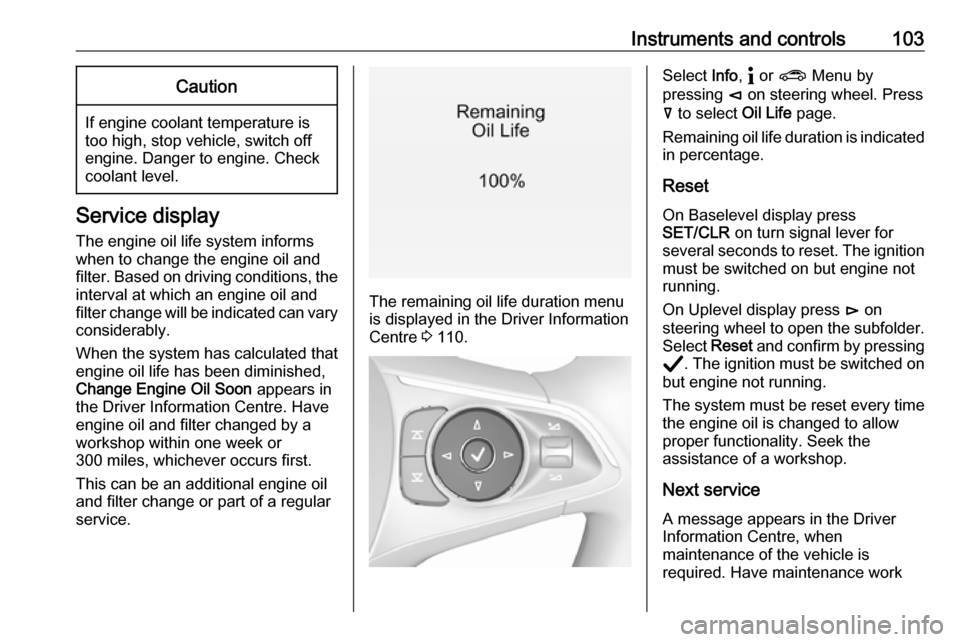
The remaining oil life duration menu
is displayed in the Driver Information
Centre 3 110.
Select Info, " or ? Menu by
pressing è on steering wheel. Press
å to select Oil Life page.
Remaining oil life duration is indicated
in percentage.
ResetOn Baselevel display press
SET/CLR on turn signal lever for
several seconds to reset. The ignition
must be switched on but engine not
running.
On Uplevel display press é on
steering wheel to open the subfolder. Select Reset and confirm by pressing
Å . The ignition must be switched on
but engine not running.
The system must be reset every time
the engine oil is changed to allow
proper functionality. Seek the
assistance of a workshop.
Next service
A message appears in the Driver
Information Centre, when
maintenance of the vehicle is
required. Have maintenance work
Page 106 of 313

104Instruments and controlscarried out by a workshop within one
week or 300 miles, whichever occurs first.
Service information 3 276.
Control indicators The control indicators described are
not present in all vehicles. The
description applies to all instrument
versions. Depending on the
equipment, the position of the control indicators may vary. When the
ignition is switched on, most control
indicators will illuminate briefly as a
functionality test.
The control indicator colours mean:red:danger, important reminderyellow:warning, information, faultgreen:confirmation of activationblue:confirmation of activationwhite:confirmation of activation
See all control indicators on different
instrument clusters 3 96.
Turn lights
O illuminates or flashes green.
Illuminates briefly
The parking lights are switched on.
Flashes
A turn light or the hazard warning
flashers are activated.
Rapid flashing: failure of a turn light or associated fuse, failure of turn light on
trailer.
Bulb replacement 3 237.
Fuses 3 247.
Turn lights 3 134.
Seat belt reminder
Seat belt reminder on front seats
X for driver seat illuminates or flashes
red in the instrument cluster.k for front passenger seat illuminates
or flashes red in the roof console,
when seat is occupied.
Illuminates
After the ignition has been switched on until the seat belt has been
fastened.
Flashes
After having started the engine for a
maximum of 100 seconds until the
seat belt has been fastened.
Seat belt status on rear seats
X or > illuminates or flashes white (in
Baselevel Driver Information Centre)
or red (in Uplevel Driver Information Centre).
X illuminates
During 60 seconds after ignition has
been switched on: seat belt is
unfastened.
> illuminates
During 60 seconds after ignition has
been switched on: seat belt has been fastened. After this time, indicators of
Page 107 of 313
Instruments and controls105seats with fastened belts or
unchanged belt status show >
symbol.
X illuminates or flashes
Fastened seat belt has been
unfastened.
No indication
All rear seat belts are fastened before
ignition has been turned on.
Fastening the seat belt 3 57.
Airbag and belt tensioners v illuminates red.
When the ignition is switched on, the
control indicator illuminates for
approx. 4 seconds. If it does not
illuminate, does not go out after
4 seconds or illuminates whilst
driving, there is a fault in the airbag
system. Seek the assistance of a
workshop. The airbags and belt
pretensioners may fail to trigger in the
event of an accident.
Deployment of the belt pretensioners
or airbags is indicated by continuous
illumination of v.9
Warning
Have the cause of the fault
remedied immediately by a
workshop.
Belt pretensioners 3 56.
Airbag system 3 58.
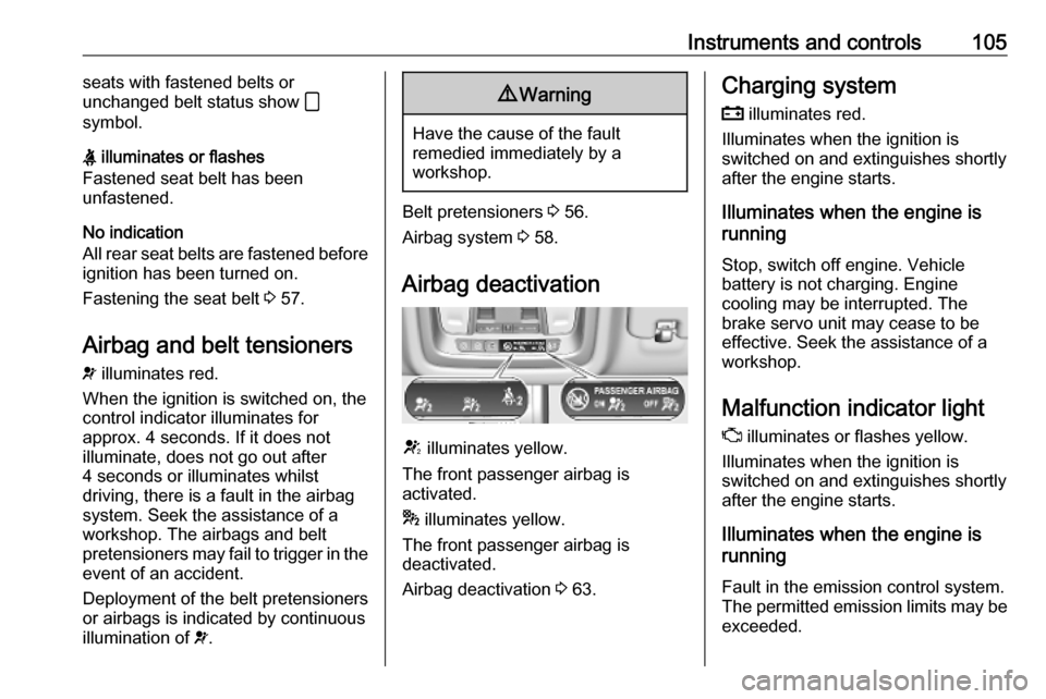
Airbag deactivation
V illuminates yellow.
The front passenger airbag is
activated.
* illuminates yellow.
The front passenger airbag is
deactivated.
Airbag deactivation 3 63.
Charging system
p illuminates red.
Illuminates when the ignition is
switched on and extinguishes shortly
after the engine starts.
Illuminates when the engine is
running
Stop, switch off engine. Vehicle
battery is not charging. Engine
cooling may be interrupted. The
brake servo unit may cease to be
effective. Seek the assistance of a
workshop.
Malfunction indicator light
Z illuminates or flashes yellow.
Illuminates when the ignition is
switched on and extinguishes shortly
after the engine starts.
Illuminates when the engine is
running
Fault in the emission control system.The permitted emission limits may be
exceeded.