parking brake VAUXHALL MERIVA 2015.5 User Guide
[x] Cancel search | Manufacturer: VAUXHALL, Model Year: 2015.5, Model line: MERIVA, Model: VAUXHALL MERIVA 2015.5Pages: 247, PDF Size: 7.83 MB
Page 147 of 247

Driving and operating145
If the vehicle battery is discharged,
start the vehicle using jump leads
3 210.
If the vehicle battery is not the cause
of the fault, release the selector lever.
1. Apply the parking brake.
2. Hold the selector lever trim at the marked position and pull tounlatch at the back.
3. Fold the selector lever trim upwards. Pull to unlatch at the
front.
4. Move the selector lever trim to the
left. Take care that the plug and
the wiring harness at the bottom are not damaged.
5. Insert a screwdriver into the opening as far as it will go and
move the selector lever out of P or
N . If P or N is engaged again, the
selector lever will be locked in
position again. Have the cause of
the power supply interruption
remedied by a workshop.
6. Mount the selector lever trim onto
the centre console and refit.
Manual transmission
To engage reverse, depress the
clutch pedal and press the release button on the selector lever and
engage the gear.
If the gear does not engage, set the
lever to neutral, release the clutch
pedal and depress again; then repeat
gear selection.
Do not slip the clutch unnecessarily.
When operating, depress the clutch
pedal completely. Do not use the
pedal as a foot rest.
Page 149 of 247

Driving and operating147
Fault9Warning
If there is a fault in the ABS, the
wheels may be liable to lock due
to braking that is heavier than
normal. The advantages of ABS are no longer available. During
hard braking, the vehicle can no longer be steered and may
swerve.
Have the cause of the fault remedied
by a workshop.
Parking brake
Electric parking brake
Applying when vehicle is stationary
9 Warning
Pull switch m for approx. one
second, the electric parking brake
operates automatically with an
adequate force. For maximum
force, e.g. parking with trailer or on
inclines, pull switch m twice.
The electric parking brake is
applied when control indicator m
illuminates 3 96.
The electric parking brake can always
be activated, even if the ignition is off.
Do not operate electric parking brake
system too often with engine not
running as this will discharge the
vehicle battery.
Before leaving the vehicle, check the electric parking brake status.
Control indicator m 3 96.
Releasing
Switch on ignition. Keep brake pedal
depressed and then push switch m.
Drive away function
Depressing clutch pedal (manual
transmission) or engaging D
(automatic transmission) and then
depressing the accelerator pedal
releases the electric parking brake
Page 150 of 247

148Driving and operating
automatically. This is not possible
when the switch m is pulled at the
same time.
This function also helps driving away
on inclines.
Aggressive drive-away may reduce
lifetime of wear parts.
Dynamic braking when vehicle is
moving
When the vehicle is moving and
switch m is kept pulled, the electric
parking brake system will decelerate the vehicle, but will not apply
statically.
As soon as switch m is released,
dynamic braking will be stopped.
Fault
Failure mode of electric parking brake
is indicated by control indicator j and
by a code number or a vehicle
message which is displayed in the
Driver Information Centre.
Control indicator j 3 96, vehicle
messages 3 105.Apply electric parking brake: pull and
hold switch m for more than
5 seconds. If control indicator m
illuminates, electric parking brake is
applied.
Release electric parking brake: push
and hold switch m for more than
2 seconds. If control indicator m
extinguishes, electric parking brake is
released.
Control indicator m flashes: electric
parking brake is not fully applied or released. When continuously
flashing, release electric parking
brake and retry applying.
Control indicator m 3 96.
Brake assist
If the brake pedal is depressed
quickly and forcefully, maximum
brake force is automatically applied
(full braking).
Maintain steady pressure on the
brake pedal for as long as full braking
is required. Maximum brake force is
automatically reduced when the
brake pedal is released.Hill start assist
The system helps prevent unintended movement when driving away on
inclines.
When releasing the foot brake after
stopping on an incline, the brakes
remain on for a further 2 seconds. The brakes release automatically as soon
as the vehicle begins to accelerate.
The hill start assist is not active during
an Autostop.
Page 170 of 247
168Vehicle careVehicle careGeneral Information...................168
Vehicle checks ........................... 169
Bulb replacement .......................176
Electrical system ........................186
Vehicle tools .............................. 192
Wheels and tyres .......................193
Jump starting ............................. 210
Towing ....................................... 212
Appearance care .......................214General Information
Accessories and vehicle
modifications
We recommend the use of genuine parts and accessories and factory
approved parts specific for your
vehicle type. We cannot assess or
guarantee reliability of other products
- even if they have a regulatory or
otherwise granted approval.
Do not make any modifications to the electrical system, e.g. changes of
electronic control units (chip tuning).Caution
When transporting the vehicle on
a train or on a recovery vehicle, the
mud flaps might be damaged.
Vehicle storage
Storage for a long period of time
If the vehicle is to be stored for several months:
■ Wash and wax the vehicle.
■ Have the wax in the engine compartment and underbody
checked.
■ Clean and preserve the rubber seals.
■ Fill up fuel tank completely.
■ Change the engine oil.
■ Drain the washer fluid reservoir.
■ Check the coolant antifreeze and corrosion protection.
■ Adjust tyre pressure to the value specified for full load.
■ Park the vehicle in a dry, well ventilated place. Engage first orreverse gear or set selector lever to P . Prevent the vehicle from rolling.
■ Do not apply the parking brake.
Page 191 of 247
Vehicle care189
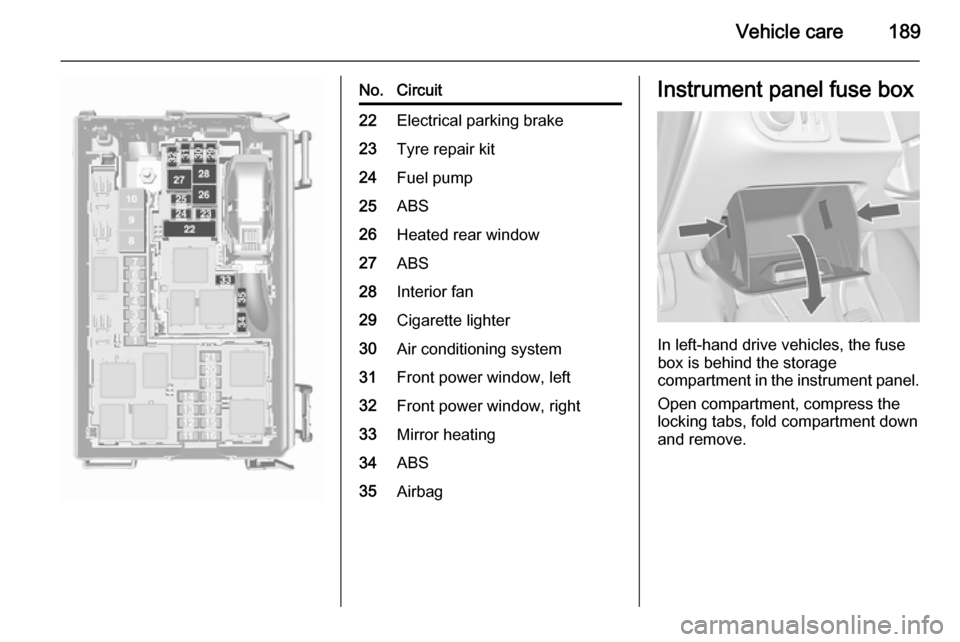
No.Circuit22Electrical parking brake23Tyre repair kit24Fuel pump25ABS26Heated rear window27ABS28Interior fan29Cigarette lighter30Air conditioning system31Front power window, left32Front power window, right33Mirror heating34ABS35AirbagInstrument panel fuse box
In left-hand drive vehicles, the fuse
box is behind the storage
compartment in the instrument panel.
Open compartment, compress the
locking tabs, fold compartment down and remove.
Page 199 of 247

Vehicle care197
matching process should also be
performed after replacing a spare tyre with a road tyre containing the TPMS
sensor.
The malfunction light w and the
warning message or code should go
off at the next ignition cycle. The
sensors are matched to the tyre/
wheel positions, using a TPMS
relearn tool, in the following order: left
side front tyre, right side front tyre,
right side rear tyre and left side rear
tyre. The turn light at the current
active position is illuminated until
sensor is matched.
Consult your workshop for service or
to purchase a relearn tool. There are
2 minutes to match the first tyre/wheel position, and 5 minutes overall to
match all four tyre/wheel positions. If
it takes longer, the matching process
stops and must be restarted.The TPMS sensor matching process is:
1. Apply the parking brake; on vehicles with automatic
transmission set the selector lever
to P.
2. Turn the ignition on.
3. Press MENU on the turn signal
lever to select the Vehicle
Information Menu in the Driver
Information Centre (DIC).
4. Turn the adjuster wheel to scroll to
the tyre pressure menu.
5. Press the SET/CLR button to
begin the sensor matching
process. A message requesting
acceptance of the process should
display.
6. Press the SET/CLR button again
to confirm the selection. The horn sounds twice to signal the
receiver is in relearn mode.
7. Start with the left side front tyre.
8. Place the relearn tool against the tyre sidewall, near the valve stem.Then press the button to activate
the TPMS sensor. A horn chirpconfirms that the sensor
identification code has been
matched to this tyre and wheel
position.
9. Proceed to the right side front tyre,
and repeat the procedure in Step 8.
10. Proceed to the right side rear tyre,
and repeat the procedure in
Step 8.
11. Proceed to the left side rear tyre, and repeat the procedure in
Step 8. The horn sounds twice to
indicate the sensor identification
code has been matched to the left side rear tyre, and the TPMS
sensor matching process is no
longer active.
12. Turn off the ignition.
13. Set all four tyres to the recommended air pressure level
as indicated on the tyre pressure
label.
14. Ensure the tyre loading status is set according selected pressure
3 100.
Page 201 of 247
Vehicle care199
If the wheel covers and tyres used are
not factory approved, the tyres must
not have a rim protection ridge.
Wheel covers must not impair brake
cooling.9 Warning
Use of unsuitable tyres or wheel
covers could lead to sudden
pressure loss and thereby
accidents.
Steel wheels: When using locking
wheel bolts, do not attach wheel
covers.
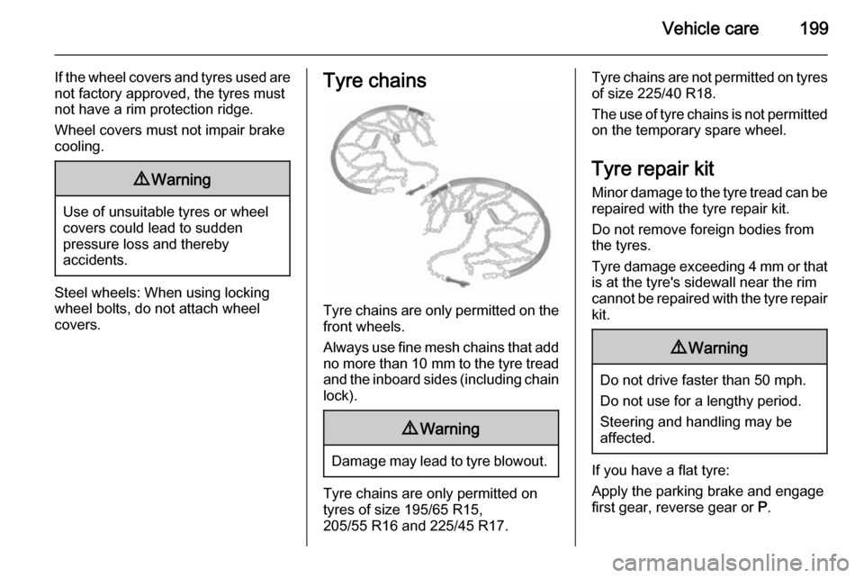
Tyre chains
Tyre chains are only permitted on the
front wheels.
Always use fine mesh chains that add no more than 10 mm to the tyre tread
and the inboard sides (including chain lock).
9 Warning
Damage may lead to tyre blowout.
Tyre chains are only permitted on
tyres of size 195/65 R15,
205/55 R16 and 225/45 R17.
Tyre chains are not permitted on tyres of size 225/40 R18.
The use of tyre chains is not permitted on the temporary spare wheel.
Tyre repair kit
Minor damage to the tyre tread can be
repaired with the tyre repair kit.
Do not remove foreign bodies from
the tyres.
Tyre damage exceeding 4 mm or that
is at the tyre's sidewall near the rim
cannot be repaired with the tyre repair kit.9 Warning
Do not drive faster than 50 mph.
Do not use for a lengthy period.
Steering and handling may be
affected.
If you have a flat tyre:
Apply the parking brake and engage
first gear, reverse gear or P.
Page 207 of 247
Vehicle care205
Make the following preparations and
observe the following information:
■ Park the vehicle on a level, firm and
non-skid surface. The front wheels
must be in the straight-ahead
position.
■ Apply the parking brake and engage first gear, reverse gear or
P .
■ Remove the spare wheel 3 208.
■ Never change more than one wheel
at once.
■ Use the jack only to change wheels
in case of puncture, not for
seasonal winter or summer tyre
change.
■ The jack is maintenance-free.
■ If the ground on which the vehicle is standing is soft, a solid board
(max. 1 cm thick) should be placed
under the jack.
■ Take heavy objects out of the vehicle before jacking up.
■ No people or animals may be in the
vehicle when it is jacked-up.■ Never crawl under a jacked-up vehicle.
■ Do not start the vehicle when it is raised on the jack.
■ Before screwing in the wheel bolts,
clean them and lightly coat the
taper of each wheel bolt with
commercially available grease.9 Warning
Do not grease the thread of the
wheel bolt.
1. Pull off the wheel cover.
For wheel covers with visible
wheel bolts: The cover can remain
on the wheel. Do not remove the
retaining rings on the wheel bolts.
Alloy wheels: Disengage wheel
bolt caps with a screwdriver and
remove. To protect the wheel,
place a soft cloth between the
screwdriver and the alloy wheel.
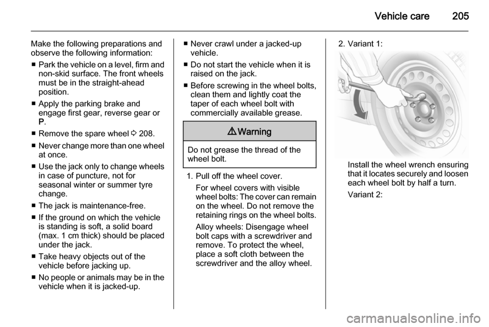
2. Variant 1:
Install the wheel wrench ensuring
that it locates securely and loosen
each wheel bolt by half a turn.
Variant 2:
Page 213 of 247
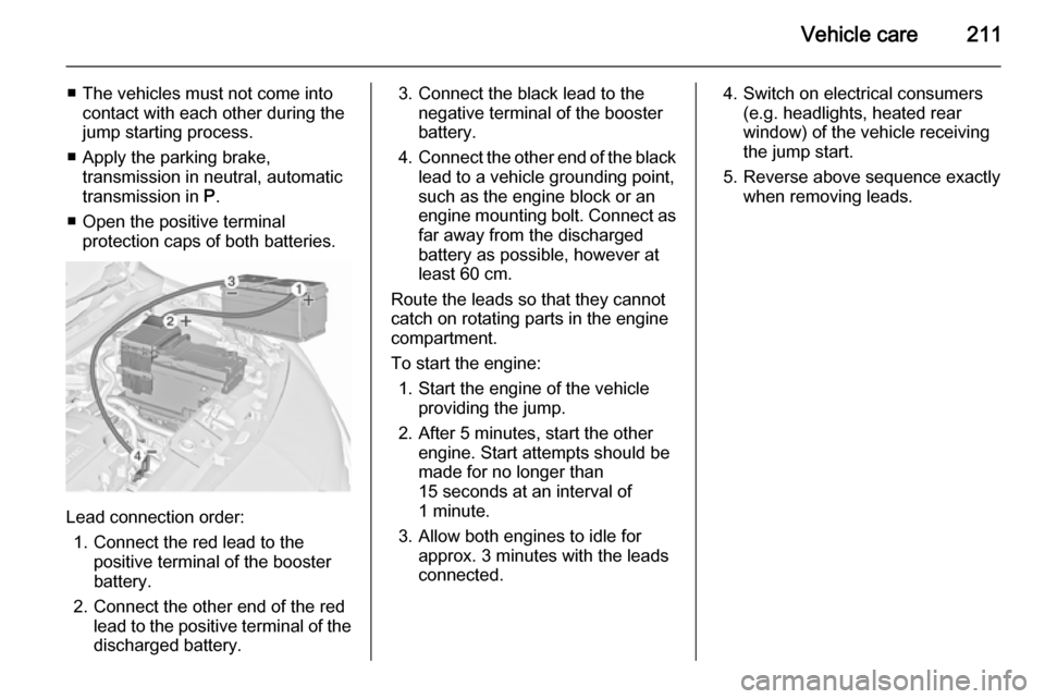
Vehicle care211
■ The vehicles must not come intocontact with each other during the
jump starting process.
■ Apply the parking brake, transmission in neutral, automatic
transmission in P.
■ Open the positive terminal protection caps of both batteries.
Lead connection order:
1. Connect the red lead to the positive terminal of the booster
battery.
2. Connect the other end of the red lead to the positive terminal of the
discharged battery.
3. Connect the black lead to the negative terminal of the booster
battery.
4. Connect the other end of the black
lead to a vehicle grounding point,
such as the engine block or an
engine mounting bolt. Connect as far away from the discharged
battery as possible, however at
least 60 cm.
Route the leads so that they cannot
catch on rotating parts in the engine
compartment.
To start the engine: 1. Start the engine of the vehicle providing the jump.
2. After 5 minutes, start the other engine. Start attempts should be
made for no longer than
15 seconds at an interval of
1 minute.
3. Allow both engines to idle for approx. 3 minutes with the leads
connected.4. Switch on electrical consumers (e.g. headlights, heated rear
window) of the vehicle receiving
the jump start.
5. Reverse above sequence exactly when removing leads.
Page 243 of 247

241
Child restraint systems ................54
Cigarette lighter ........................... 89
Climate control ............................. 15
Climate control, service ..............133
Climate control systems .............125
Clock............................................. 86
Code ........................................... 105
Control indicators.......................... 92
Control of the vehicle .................135
Controls ........................................ 82
Controls in steering wheel ............82
Convex shape .............................. 29
Coolant ....................................... 171
Coolant and antifreeze ...............218
Coolant temperature gauge ..........91
Coupling ball bar ........................164
Cruise control ...................... 99, 150
Cupholders .................................. 61
Curtain airbag system .................. 52
Curve lighting.............................. 119
D Danger, Warnings and Cautions ...4
Dashboard .................................... 10
Daytime running light ..................117
Daytime running lights ...............119
Declaration of conformity ............236
Diesel fuel system bleeding .......176
Diesel particle filter ....................141
Door open .................................... 99Doors............................................ 25
Driver assistance systems ..........150
Driver Information Centre ...........100
Driving characteristics and towing tips .............................. 163
Driving hints ................................ 135
E Electric adjustment ......................29
Electrical system......................... 186
Electric parking brake ...........96, 147
Electric parking brake fault ...........96
Electronic climate control system 128
Electronic driving programmes ..144
Electronic Stability Control.......... 149
Electronic Stability Control and Traction Control system ...........97
Electronic Stability Control off ...... 97
End-of-life vehicle recovery .......169
Engine compartment fuse box ...187
Engine coolant ........................... 171
Engine coolant temperature gauge ....................................... 91
Engine data ............................... 225
Engine exhaust .......................... 141
Engine identification ...................221
Engine oil ................... 170, 218, 222
Engine oil pressure ......................98
Entry lighting .............................. 123
Event data recorders ..................237Exhaust gases ............................ 141
Exit lighting ................................ 123
Exterior care .............................. 214
Exterior light ................................. 99
Exterior lighting ....................12, 116
Exterior mirrors ............................. 29
F
Fault ........................................... 144
First aid ......................................... 79
First aid kit ................................... 79
Fixed air vents ........................... 133
Flex-Fix system ............................ 64
Fog light ....................................... 99
Fog lights .................... 120, 121, 180
Folding mirrors ............................. 29
Folding tray .................................. 78
Front airbag system .....................51
Front fog lights ........................... 120
Front seats.................................... 36
Front storage ............................... 63
Front turn signal light ..................176
Front turn signal lights ...............181
Fuel............................................. 156
Fuel consumption - CO 2-
Emissions ............................... 162
Fuel for diesel engines ..............156
Fuel for liquid gas operation .......157
Fuel for petrol engines ...............156
Fuel gauge ................................... 90