VAUXHALL MERIVA 2015.5 Manual Online
Manufacturer: VAUXHALL, Model Year: 2015.5, Model line: MERIVA, Model: VAUXHALL MERIVA 2015.5Pages: 247, PDF Size: 7.83 MB
Page 81 of 247

Storage79First aid kit
Stow the first aid kit and the high
visibility vest under the driver's seat.
Use the straps.
Depending on the vehicle, a box is
located under the driver's seat. Pull handle and fold down the cover.
Maximum load: 1.5 kg.
Roof rack system
Roof rack For safety reasons and to avoid
damage to the roof, the vehicle
approved roof rack system is
recommended. For further
information contact your workshop.
Follow the installation instructions
and remove the roof rack when not in
use.
Detach the cover from each mounting
point.
Page 82 of 247

80StorageLoading information
■ Heavy objects in the loadcompartment should be placedagainst the seat backrests. Ensure
that the backrests are securely
engaged. If objects can be stacked, heavier objects should be placed at
the bottom.
■ Secure objects with lashing straps attached to the lashing eyes 3 77.
■ Use the hook at the left sidewall of
the load compartment for hanging
up carrier bags. Pull out the hook.
Maximum load: 3 kg.
■ Secure loose objects in the load compartment to prevent them from
sliding.
■ When transporting objects in the load compartment, the backrests ofthe rear seats must not be angled
forward.
■ Do not allow the load to protrude above the upper edge of the
backrests.
■ Do not place any objects on the load compartment cover or the
instrument panel, and do not cover
the sensor on top of the instrument
panel.
■ The load must not obstruct the operation of the pedals, parking
brake and gear selector, or hinder the freedom of movement of thedriver. Do not place any unsecured objects in the interior.
■ Do not drive with an open load compartment.9 Warning
Always make sure that the load in
the vehicle is securely stowed.
Otherwise objects can be thrown
around inside the vehicle and
cause personal injury or damage
to the load or vehicle.
■ The payload is the difference between the permitted gross
vehicle weight (see identification
plate 3 221) and the EC kerb
weight.
Page 83 of 247

Storage81
To calculate the payload, enter the
data for your vehicle in the Weights
table at the front of this manual.
The EC kerb weight includes
weights for the driver (68 kg),
luggage (7 kg) and all fluids (tank
90 % full).
Optional equipment and
accessories increase the kerb
weight.
■ Driving with a roof load increases the sensitivity of the vehicle to
cross-winds and has a detrimental
effect on vehicle handling due to
the vehicle's higher centre of
gravity. Distribute the load evenly
and secure it properly with retaining
straps. Adjust the tyre pressure and vehicle speed according to the load
conditions. Check and retighten the straps frequently.
Do not drive faster than 75 mph.
The permissible roof load is 60 kg. The roof load is the combined
weight of the roof rack and the load.
Page 84 of 247

82Instruments and controlsInstruments and
controlsControls ....................................... 82
Warning lights, gauges and indi‐
cators ........................................... 89
Information displays ...................100
Vehicle messages ...................... 105
Trip computer ............................. 109
Vehicle personalisation ..............112Controls
Steering wheel adjustment
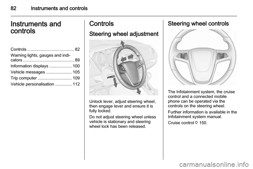
Unlock lever, adjust steering wheel,
then engage lever and ensure it is fully locked.
Do not adjust steering wheel unless
vehicle is stationary and steering
wheel lock has been released.
Steering wheel controls
The Infotainment system, the cruise
control and a connected mobile
phone can be operated via the
controls on the steering wheel.
Further information is available in the
Infotainment system manual.
Cruise control 3 150.
Page 85 of 247

Instruments and controls83Heated steering wheel
Activate heating by pressing *.
Activation is indicated by the LED in
the button.
The highlighted grip areas of the
steering wheel are heated quicker
and to a higher temperature than the
other areas.
Heating is operational when the
engine is running and during an
Autostop.
Stop-start system 3 138.
Horn
Press j.
Page 86 of 247

84Instruments and controlsWindscreen wiper/washer
Windscreen wiperHI=fastLO=slowINT=interval wiping or automatic
wiping with rain sensorOFF=off
For a single wipe when the
windscreen wiper is off, press the
lever down to position 1x.
Do not use if the windscreen is frozen.
Switch off in car washes.
Adjustable wiper interval
Wiper lever in position INT.
Turn the adjuster wheel to adjust the
desired wipe interval:
short interval=turn adjuster
wheel upwardslong interval=turn adjuster
wheel downwardsAutomatic wiping with rain sensorINT=automatic wiping with rain
sensor
The rain sensor detects the amount of water on the windscreen and
automatically regulates the frequency
of the windscreen wiper.
Page 87 of 247

Instruments and controls85
Adjustable sensitivity of the rain
sensor
Turn the adjuster wheel to adjust the
sensitivity:
low sensitivity=turn adjuster
wheel downwardshigh sensitivity=turn adjuster
wheel upwards
Keep the sensor free from dust, dirt
and ice.
Windscreen washer
Pull lever. Washer fluid is sprayed
onto the windscreen and the wiper
wipes a few times.
Rear window wiper/washer
Press the rocker switch to activate the
rear window wiper:
upper position=continuous
operationlower position=intermittent
operationmiddle position=off
Page 88 of 247

86Instruments and controls
Push lever. Washer fluid is sprayed
onto the rear window and the wiper
wipes a few times.
Do not use if the windscreen is frozen.
Switch off in car washes.
The rear window wiper comes on
automatically when the windscreen
wiper is operating and reverse gear is engaged.
Activation or deactivation of this
function can be changed in the
Settings menu in the Info-Display.
Vehicle personalisation 3 112.
Outside temperature
A drop in temperature is indicated
immediately and a rise in temperature
after a time delay.
If outside temperature drops to 3 °C, a warning message is displayed in the Driver Information Centre with
Uplevel-Display or
Uplevel-Combi-Display.
9 Warning
The road surface may already be
icy even though the display
indicates a few degrees above 0
°C.
Clock
Date and time are shown in the
Info-Display.
Page 89 of 247

Instruments and controls87
Time and date settings
CD 300/CD 400/CD 400plus
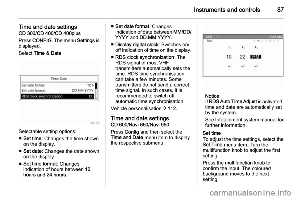
Press CONFIG . The menu Settings is
displayed.
Select Time & Date .
Selectable setting options:
■ Set time : Changes the time shown
on the display.
■ Set date : Changes the date shown
on the display.
■ Set time format : Changes
indication of hours between 12
hours and 24 hours .
■Set date format : Changes
indication of date between MM/DD/
YYYY and DD.MM.YYYY .
■ Display digital clock : Switches on/
off indication of time on the display.
■ RDS clock synchronization : The
RDS signal of most VHF
transmitters automatically sets the time. RDS time synchronisation
can take a few minutes. Some
transmitters do not send a correct
time signal. In such cases, it is
recommended to switch off
automatic time synchronisation.
Vehicle personalisation 3 112.
Time and date settings
CD 600/Navi 650/Navi 950
Press Config and then select the
Time and Date menu item to display
the respective submenu.
Notice
If RDS Auto Time Adjust is activated,
time and date are automatically set
by the system.
See Infotainment system manual for further information.
Set time
To adjust the time settings, select the
Set Time menu item. Turn the
multifunction knob to adjust the first
setting.
Press the multifunction knob to
confirm the input. The coloured
background moves to the next
setting.
Page 90 of 247

88Instruments and controls
Adjust all settings.
Set date
To adjust the time settings, select the
Set Date menu item. Turn the
multifunction knob to adjust the first
setting.
Press the multifunction knob to
confirm the input. The coloured
background moves to the next
setting.
Adjust all settings.
Time format
To choose the desired time format,
select 12 hr / 24 hr Format . Activate
12 Hour or 24 Hour .
Vehicle personalisation 3 112.Power outlets
A 12 volt power outlet is located in the
front console.
A further 12 volt power outlet is
located in the rear console.
Do not exceed the maximum power
consumption of 120 watts.
With ignition off, the power outlets are
deactivated. Additionally the power
outlets are deactivated in the event of
low vehicle battery voltage.
Electrical accessories that are
connected must comply with the
electromagnetic compatibility
requirements laid down in
DIN VDE 40 839.
Do not connect any current-delivering
accessories, e.g. electrical charging
devices or batteries.
Do not damage the outlet by using
unsuitable plugs.
Stop-start system 3 138.