stop start VAUXHALL MERIVA 2016.5 Owner's Guide
[x] Cancel search | Manufacturer: VAUXHALL, Model Year: 2016.5, Model line: MERIVA, Model: VAUXHALL MERIVA 2016.5Pages: 251, PDF Size: 8.04 MB
Page 146 of 251
144Driving and operatingEngine exhaust9Danger
Engine exhaust gases contain
poisonous carbon monoxide,
which is colourless and odourless and could be fatal if inhaled.
If exhaust gases enter the interior
of the vehicle, open the windows.
Have the cause of the fault
rectified by a workshop.
Avoid driving with an open load
compartment, otherwise exhaust
gases could enter the vehicle.
Diesel particle filter
The diesel particle filter system filters
harmful soot particles out of the
exhaust gases. The system includes
a self-cleaning function that runs
automatically during driving without
any notification. The filter is cleaned
by periodically burning off the soot
particles at high temperature. This
process takes place automatically
under set driving conditions and may
take up to 25 minutes. Typically it
needs between 7 and 12 minutes.
Autostop is not available and fuel
consumption may be higher during
this period. The emission of smells
and smoke during this process is
normal.
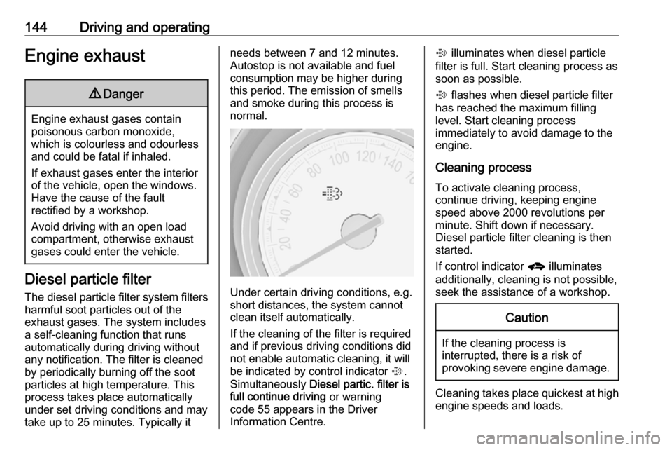
Under certain driving conditions, e.g.
short distances, the system cannot
clean itself automatically.
If the cleaning of the filter is required
and if previous driving conditions did
not enable automatic cleaning, it will
be indicated by control indicator %.
Simultaneously Diesel partic. filter is
full continue driving or warning
code 55 appears in the Driver
Information Centre.
% illuminates when diesel particle
filter is full. Start cleaning process as
soon as possible.
% flashes when diesel particle filter
has reached the maximum filling
level. Start cleaning process
immediately to avoid damage to the
engine.
Cleaning process To activate cleaning process,
continue driving, keeping engine
speed above 2000 revolutions per
minute. Shift down if necessary.
Diesel particle filter cleaning is then
started.
If control indicator g illuminates
additionally, cleaning is not possible,
seek the assistance of a workshop.Caution
If the cleaning process is
interrupted, there is a risk of
provoking severe engine damage.
Cleaning takes place quickest at high
engine speeds and loads.
Page 149 of 251
![VAUXHALL MERIVA 2016.5 Owners Guide Driving and operating147Manual mode
Move selector lever out of position D
towards the left and then forwards or backwards.
<:shift to a higher gear]:shift to a lower gear
If a higher gear is selected VAUXHALL MERIVA 2016.5 Owners Guide Driving and operating147Manual mode
Move selector lever out of position D
towards the left and then forwards or backwards.
<:shift to a higher gear]:shift to a lower gear
If a higher gear is selected](/img/38/19520/w960_19520-148.png)
Driving and operating147Manual mode
Move selector lever out of position D
towards the left and then forwards or backwards.
<:shift to a higher gear]:shift to a lower gear
If a higher gear is selected when
vehicle speed is too low, or a lower
gear when vehicle speed is too high,
the shift is not executed. This can
cause a message in the Driver
Information Centre.
In manual mode, no automatic
shifting to a higher gear takes place
at high engine revolutions.
Electronic driving
programmes
● Following a cold start, the operating temperature
programme increases engine
speed to quickly bring the
catalytic converter to the required
temperature.
● The automatic neutral shift function automatically shifts to
idling when the vehicle is stopped with a forward gear engaged and
the brake pedal is pressed.
● Special programmes automatically adapt the shiftingpoints when driving up inclines or
down hills.
Kickdown If the accelerator pedal is pressed
down completely in automatic mode,
the transmission shifts to a lower gear
depending on engine speed.Fault
In the event of a fault, g illuminates.
Additionally a code number or a
vehicle message is displayed in the
Driver Information Centre. Vehicle
messages 3 105.
The transmission no longer shifts automatically. Continued travel is
possible with manual shifting.
Only the highest gear is available.
Depending on the fault, second gear
may also be available in manual
mode. Shift only when vehicle is at a
standstill.
Have the cause of the fault remedied
by a workshop.
Interruption of power supply
In the event of an interruption of
power supply, the selector lever
cannot be moved out of the P
position. The ignition key cannot be
removed from the ignition switch.
If the vehicle battery is discharged,
start the vehicle using jump leads
3 212.
Page 151 of 251

Driving and operating149Caution
It is not advisable to drive with thehand resting on the selector lever.
Stop-start system 3 141.
Brakes
The brake system comprises two
independent brake circuits.
If a brake circuit fails, the vehicle can
still be braked using the other brake
circuit. However, braking effect is
achieved only when the brake pedal
is depressed firmly. Considerably
more force is needed for this. The
braking distance is extended. Seek the assistance of a workshop before
continuing the journey.
When the engine is not running, the
support of the brake servo unit
disappears once the brake pedal has been depressed once or twice.
Braking effect is not reduced, but
braking requires significantly greater
force. It is especially important to bear this in mind when being towed.
Control indicator R 3 95.
Antilock brake system
Antilock brake system (ABS)
prevents the wheels from locking.ABS starts to regulate brake pressure as soon as a wheel shows a tendency to lock. The vehicle remains
steerable, even during hard braking.
ABS control is made apparent
through a pulse in the brake pedal
and the noise of the regulation
process.
For optimum braking, keep the brake
pedal fully depressed throughout the
braking process, despite the fact that
the pedal is pulsating. Do not reduce
the pressure on the pedal.
After starting off, the system performs
a self-test which may be audible.
Control indicator u 3 96.
Adaptive brake light
During full braking, all three brake
lights flash for the duration of ABS
control.
Page 153 of 251

Driving and operating151brake automatically. This is not
possible when the switch m is pulled
at the same time.
Vehicles with automatic transmission:
Engaging D and then depressing the
accelerator pedal releases the
electric parking brake automatically.
This is not possible when the switch
m is pulled at the same time.
Dynamic braking when vehicle is
moving
When the vehicle is moving and
switch m is kept pulled, the electric
parking brake system will decelerate the vehicle, but will not apply
statically.
As soon as switch m is released,
dynamic braking will be stopped.
Fault
Failure mode of electric parking brake
is indicated by control indicator j and
by a code number or a vehicle
message which is displayed in the
Driver Information Centre.
Control indicator j 3 96, vehicle
messages 3 105.Apply electric parking brake: pull and
hold switch m for more than
five seconds. If control indicator m
illuminates, electric parking brake is
applied.
Release electric parking brake: push
and hold switch m for more than
two seconds. If control indicator m
extinguishes, electric parking brake is
released.
Control indicator m flashes: electric
parking brake is not fully applied or released. When continuously
flashing, release electric parking
brake and retry applying.
Control indicator m 3 96.
Brake assist If the brake pedal is depressed
quickly and forcefully, maximum
brake force is automatically applied
(full braking).
Maintain steady pressure on the
brake pedal for as long as full braking
is required. Maximum brake force is
automatically reduced when the
brake pedal is released.Hill start assist
The system helps prevent unintendedmovement when driving away on
inclines.
When releasing the foot brake after
stopping on an incline, the brakes
remain on for a further two seconds.
The brakes release automatically as
soon as the vehicle begins to
accelerate.
The hill start assist is not active during
an Autostop.
Stop-start system 3 141.
Page 175 of 251
Vehicle care173
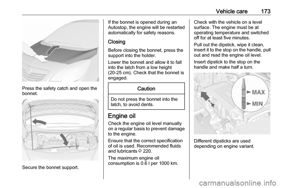
Press the safety catch and open the
bonnet.
Secure the bonnet support.
If the bonnet is opened during an
Autostop, the engine will be restarted automatically for safety reasons.
Closing
Before closing the bonnet, press the
support into the holder.
Lower the bonnet and allow it to fall
into the latch from a low height
(20-25 cm). Check that the bonnet is engaged.Caution
Do not press the bonnet into the
latch, to avoid dents.
Engine oil
Check the engine oil level manually
on a regular basis to prevent damage
to the engine.
Ensure that the correct specification
of oil is used. Recommended fluids
and lubricants 3 220.
The maximum engine oil
consumption is 0.6 l per 1000 km.
Check with the vehicle on a level
surface. The engine must be at
operating temperature and switched
off for at least five minutes.
Pull out the dipstick, wipe it clean,
insert it to the stop on the handle, pull
out and read the engine oil level.
Insert dipstick to the stop on the
handle and make half a turn.
Different dipsticks are used
depending on engine variant.
Page 178 of 251
176Vehicle care
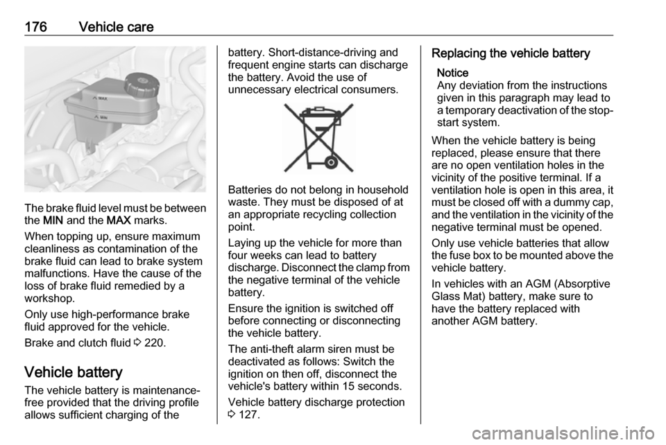
The brake fluid level must be betweenthe MIN and the MAX marks.
When topping up, ensure maximum cleanliness as contamination of the
brake fluid can lead to brake system
malfunctions. Have the cause of the
loss of brake fluid remedied by a
workshop.
Only use high-performance brake
fluid approved for the vehicle.
Brake and clutch fluid 3 220.
Vehicle battery
The vehicle battery is maintenance-
free provided that the driving profile
allows sufficient charging of the
battery. Short-distance-driving and
frequent engine starts can discharge
the battery. Avoid the use of
unnecessary electrical consumers.
Batteries do not belong in household
waste. They must be disposed of at
an appropriate recycling collection
point.
Laying up the vehicle for more than
four weeks can lead to battery
discharge. Disconnect the clamp from the negative terminal of the vehicle
battery.
Ensure the ignition is switched off
before connecting or disconnecting
the vehicle battery.
The anti-theft alarm siren must be
deactivated as follows: Switch the
ignition on then off, disconnect the
vehicle's battery within 15 seconds.
Vehicle battery discharge protection
3 127.
Replacing the vehicle battery
Notice
Any deviation from the instructions
given in this paragraph may lead to
a temporary deactivation of the stop-
start system.
When the vehicle battery is being
replaced, please ensure that there
are no open ventilation holes in the
vicinity of the positive terminal. If a
ventilation hole is open in this area, it
must be closed off with a dummy cap, and the ventilation in the vicinity of the
negative terminal must be opened.
Only use vehicle batteries that allow
the fuse box to be mounted above the vehicle battery.
In vehicles with an AGM (Absorptive
Glass Mat) battery, make sure to
have the battery replaced with
another AGM battery.
Page 179 of 251
Vehicle care177
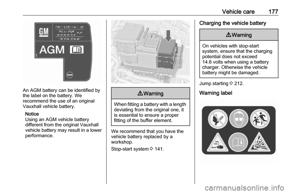
An AGM battery can be identified by
the label on the battery. We
recommend the use of an original
Vauxhall vehicle battery.
Notice
Using an AGM vehicle battery
different from the original Vauxhall
vehicle battery may result in a lower performance.
9 Warning
When fitting a battery with a length
deviating from the original one, itis essential to ensure a proper
fitting of the buffer element.
We recommend that you have the
vehicle battery replaced by a
workshop.
Stop-start system 3 141.
Charging the vehicle battery9 Warning
On vehicles with stop-start
system, ensure that the charging potential does not exceed
14.6 volts when using a battery
charger. Otherwise the vehicle
battery might be damaged.
Jump starting 3 212.
Warning label
Page 201 of 251
Vehicle care199
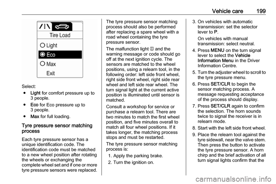
Select:● Light for comfort pressure up to
3 people.
● Eco for Eco pressure up to
3 people.
● Max for full loading.
Tyre pressure sensor matching
process
Each tyre pressure sensor has a
unique identification code. The
identification code must be matched
to a new wheel position after rotating the wheels or exchanging the
complete wheel set and if one or more tyre pressure sensors were replaced.
The tyre pressure sensor matching
process should also be performed
after replacing a spare wheel with a
road wheel containing the tyre
pressure sensor.
The malfunction light w and the
warning message or code should go
off at the next ignition cycle. The
sensors are matched to the wheel
positions, using a relearn tool, in the following order: left side front wheel,
right side front wheel, right side rear
wheel and left side rear wheel. The
turn signal light at the current active
position is illuminated until sensor is
matched.
Consult a workshop for service or
purchase a relearn tool. There are
two minutes to match the first wheel
position, and five minutes overall to
match all four wheel positions. If it
takes longer, the matching process stops and must be restarted.
The tyre pressure sensor matching
process is:
1. Apply the parking brake.
2. Turn the ignition on.3. On vehicles with automatic transmission: set the selector
lever to P.
On vehicles with manual
transmission: select neutral.
4. Press MENU on the turn signal
lever to select the Vehicle
Information Menu in the Driver
Information Centre.
5. Turn the adjuster wheel to scroll to
the tyre pressure menu.
6. Press SET/CLR to begin the
sensor matching process. A
message requesting acceptance
of the process should display.
7. Press SET/CLR again to confirm
the selection. The horn sounds
twice to signal the receiver is in
relearn mode.
8. Start with the left side front wheel.
9. Place the relearn tool against the tyre sidewall, near the valve stem.Then press the button to activate
the tyre pressure sensor. A horn
chirp and the brief activation of all turn signal lights confirm that the
Page 249 of 251

247OnStar........................................ 115
Operate pedal ............................... 95
Outside temperature ....................84
Overrun cut-off ........................... 141
P
Parking ................................ 17, 143
Parking assist ............................ 155
Parking brake ............................ 150
Parking lights ............................. 124
Particulate filter ........................... 144
Performance .............................. 229
Performing work ........................172
Personalisation ........................... 111
Pollen filter ................................. 136
Power outlets ............................... 86
Power steering fluid ....................175
Power windows ............................ 31
Preheating ................................... 97
Puncture ..................................... 206
Q
Quickheat ................................... 135
R Radio Frequency Identification (RFID) ..................................... 242
Radio remote control ...................20
Reading lights ............................ 126
Rear carrier system ......................63
Rear doors ................................... 26Rear floor storage cover ..............74
Rear fog light ............................... 99
Rear fog lights ........................... 124
Rear seats .................................... 41
Rear storage ................................. 73
Rear view camera ...................... 157
Rear window wiper/washer .......... 84
Recommended fluids and lubricants ........................ 220, 224
Reduced engine power ...............98
Refuelling ................................... 161 Remote control ............................. 20
Retained power off .....................139
Reversing lights .........................124
Ride control systems ..................152
Roof .............................................. 33
Roof load ...................................... 78
Roof rack ..................................... 78
S
Safety belts ................................... 44
Safety net .................................... 75
Seat adjustment ....................... 6, 37
Seat belt ........................................ 8
Seat belt reminder .......................94
Seat belts ..................................... 44
Seat heating ................................. 40
Seat position ................................ 36
Selector lever ............................. 146
Service ............................... 136, 219Service display ............................ 90
Service information ....................219
Service vehicle soon .................... 95
Side airbag system ......................51
Sidelights .................................... 119
Side turn signal lights ................187
Software acknowledgement .......239
Spare wheel ............................... 209
Speedometer ............................... 88
Starting and operating ................139
Starting off ................................... 16
Starting the engine ....................140
Steering ...................................... 139
Steering wheel adjustment ......9, 81
Steering wheel controls ...............81
Steering wheel, heated .................81
Stop-start system........................ 141
Storage ......................................... 60
Storage compartments .................60
Sunvisor lights ........................... 126
Sun visors .................................... 33
Symbols ......................................... 4
T
Tachometer ................................. 88
Tailgate ......................................... 26
Tail lights ................................... 184
Technical data ............................ 227
Three-point seat belt .................... 45
Tools .......................................... 194