towing VAUXHALL MERIVA 2016 Owner's Manual
[x] Cancel search | Manufacturer: VAUXHALL, Model Year: 2016, Model line: MERIVA, Model: VAUXHALL MERIVA 2016Pages: 251, PDF Size: 8.02 MB
Page 76 of 251
74StorageRemove the cover.
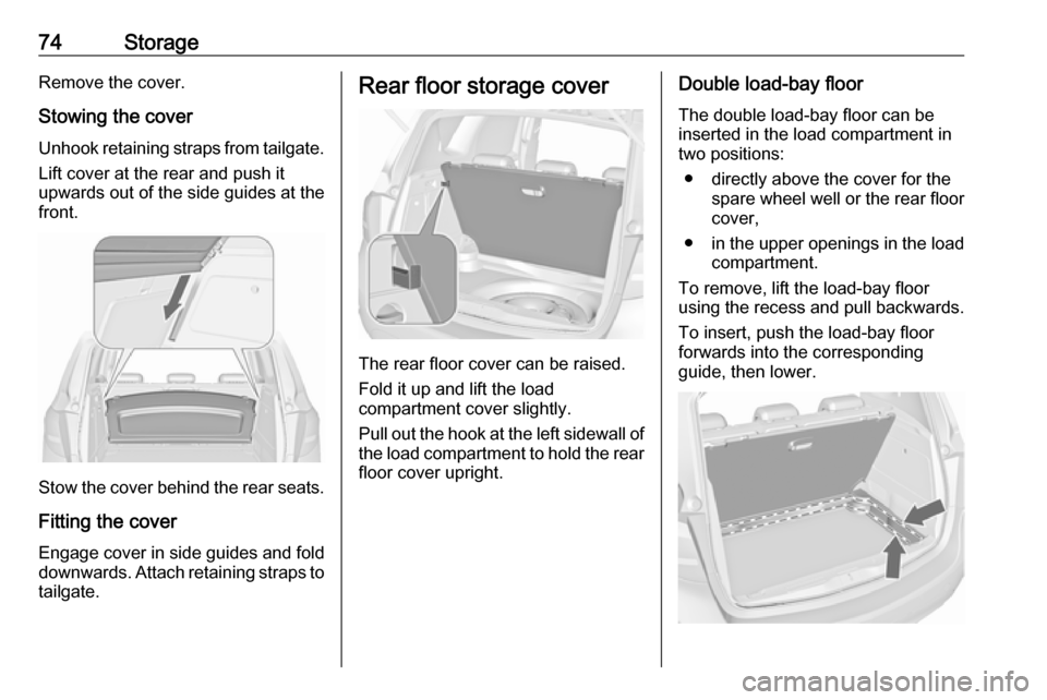
Stowing the cover Unhook retaining straps from tailgate. Lift cover at the rear and push it
upwards out of the side guides at the
front.
Stow the cover behind the rear seats.
Fitting the cover Engage cover in side guides and fold
downwards. Attach retaining straps to
tailgate.
Rear floor storage cover
The rear floor cover can be raised.
Fold it up and lift the load
compartment cover slightly.
Pull out the hook at the left sidewall of
the load compartment to hold the rear floor cover upright.
Double load-bay floor
The double load-bay floor can be
inserted in the load compartment in
two positions:
● directly above the cover for the spare wheel well or the rear floorcover,
● in the upper openings in the load
compartment.
To remove, lift the load-bay floor
using the recess and pull backwards.
To insert, push the load-bay floor
forwards into the corresponding
guide, then lower.
Page 126 of 251
124LightingRear fog lights
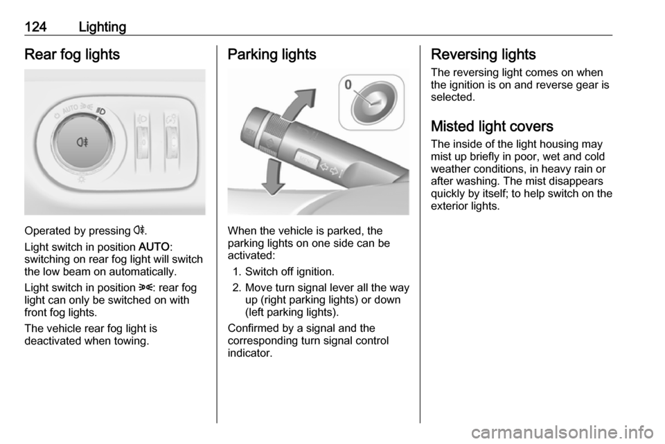
Operated by pressing r.
Light switch in position AUTO:
switching on rear fog light will switch
the low beam on automatically.
Light switch in position 8: rear fog
light can only be switched on with
front fog lights.
The vehicle rear fog light is
deactivated when towing.
Parking lights
When the vehicle is parked, the
parking lights on one side can be
activated:
1. Switch off ignition.
2. Move turn signal lever all the way up (right parking lights) or down
(left parking lights).
Confirmed by a signal and the
corresponding turn signal control
indicator.
Reversing lights
The reversing light comes on when
the ignition is on and reverse gear is
selected.
Misted light covers
The inside of the light housing may
mist up briefly in poor, wet and cold weather conditions, in heavy rain or
after washing. The mist disappears
quickly by itself; to help switch on the
exterior lights.
Page 140 of 251

138Driving and operatingDriving and
operatingDriving hints ............................... 138
Control of the vehicle ...............138
Steering ................................... 139
Starting and operating ...............139
New vehicle running-in ............139
Ignition switch positions ...........139
Retained power off ..................139
Starting the engine ..................140
Overrun cut-off ........................ 141
Stop-start system ....................141
Parking .................................... 143
Engine exhaust .......................... 144
Diesel particle filter ..................144
Catalytic converter ...................145
Automatic transmission ..............145
Transmission display ...............145
Selector lever .......................... 146
Manual mode ........................... 147
Electronic driving programmes 147
Fault ........................................ 147
Interruption of power supply ....147
Manual transmission ..................148Brakes........................................ 149
Antilock brake system .............149
Parking brake .......................... 150
Brake assist ............................. 151
Hill start assist ......................... 151
Ride control systems .................152
Traction Control system ..........152
Electronic Stability Control ......152
Driver assistance systems .........153
Cruise control .......................... 153
Parking assist .......................... 155
Rear view camera ...................157
Fuel ............................................ 159
Fuel for petrol engines .............159
Fuel for diesel engines ............159
Fuel for liquid gas operation ....159
Refuelling ................................ 161
Fuel consumption - CO 2-
Emissions .............................. 164
Trailer hitch ................................ 165
General information .................165
Driving characteristics and towing tips .............................. 166
Trailer towing ........................... 166
Towing equipment ...................167Driving hints
Control of the vehicle
Never coast with engine not
running (except during Autostop)
Many systems will not function in this
situation (e.g. brake servo unit, power steering). Driving in this manner is a
danger to yourself and others. All
systems function during an Autostop,
but there will be a controlled reduction
in power steering assist and vehicle
speed is reduced.
Stop-start system 3 141.
Idle boost
If charging of the vehicle battery is
required due to vehicle battery
condition, the power output of the
generator must be increased. This will be achieved by an idle boost whichmay be audible.
On vehicles with Uplevel-Display or
Uplevel-Combi-Display, a message
appears in the Driver Information
Centre.
Page 147 of 251
Driving and operating145Control indicator % extinguishes as
soon as the self-cleaning operation is
complete.
Catalytic converter
The catalytic converter reduces the
amount of harmful substances in the
exhaust gases.Caution
Fuel grades other than those listed on pages 3 159, 3 227 could
damage the catalytic converter or
electronic components.
Unburnt petrol will overheat and
damage the catalytic converter.
Therefore avoid excessive use of the starter, running the fuel tank
dry and starting the engine by
pushing or towing.
In the event of misfiring, uneven
engine running, a reduction in engine
performance or other unusual
problems, have the cause of the fault
rectified by a workshop as soon as
possible. In an emergency, driving
can be continued for a short period,
keeping vehicle speed and engine
speed low.Automatic transmission
The automatic transmission permits
automatic gearshifting (automatic
mode) or manual gearshifting
(manual mode).
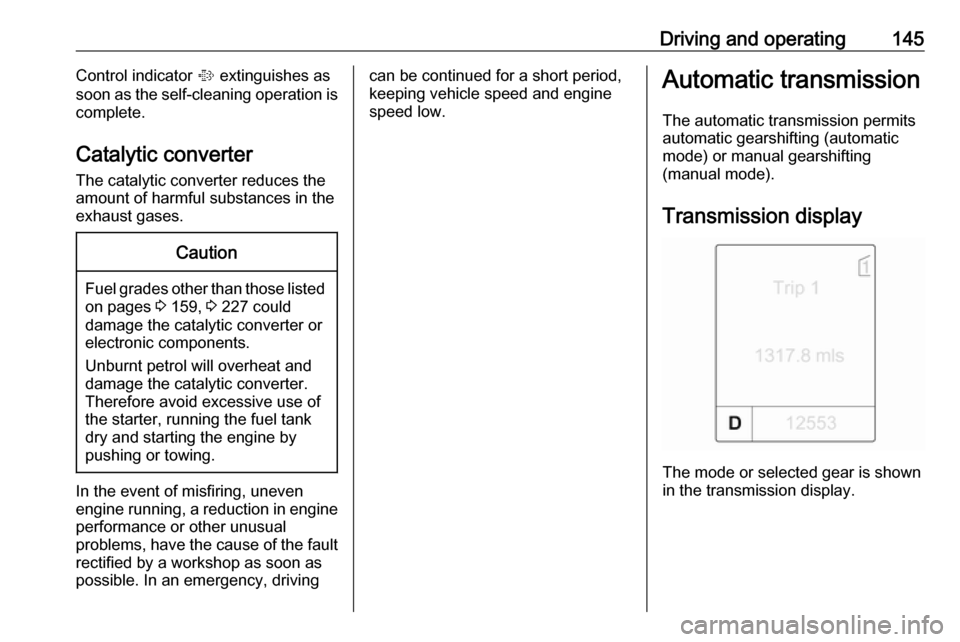
Transmission display
The mode or selected gear is shown
in the transmission display.
Page 159 of 251
Driving and operating157Notice
The parking assist system
automatically detects factory-fitted
towing equipment. It is deactivated
when the connector is plugged in.
The sensor may detect a non-
existent object (echo disturbance)
caused by external acoustic or
mechanical disturbances.
Notice
If engaging a forward gear and
exceeding a certain speed, the rear
parking assist will be deactivated
when the rear carrier system is
extended.
If engaging reverse at first, the
parking assist will detect the rear
carrier system and provide a buzzing
sound. Press r briefly to
deactivate the parking assist.
Rear view camera
The rear view camera assists the
driver when reversing by displaying a view of the area behind the vehicle.
The view of the camera is displayed
in the Colour-Info-Display.9 Warning
The rear view camera does not
replace driver vision. Note that
objects that are outside the
camera's field of view and the
advanced parking assist sensors,
e.g. below the bumper or
underneath the vehicle, are not
displayed.
Do not reverse the vehicle by only looking at the Info-Display and
check the surrounding behind and
around the vehicle before
reversing.
Activation
Rear view camera is automatically
activated when reverse gear is
engaged.
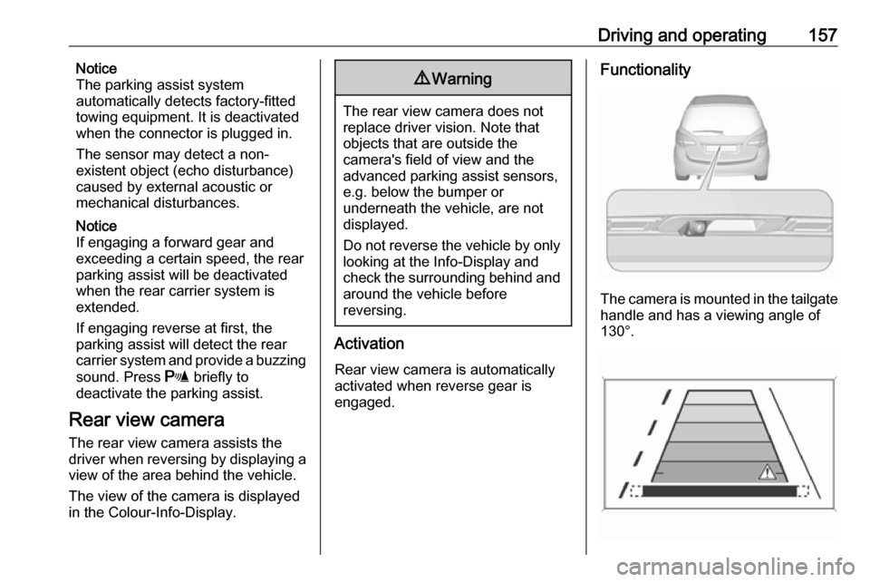
Functionality
The camera is mounted in the tailgate handle and has a viewing angle of
130°.
Page 167 of 251

Driving and operating165For the values specific for your
vehicle, refer to the EEC Certificate of
Conformity provided with your vehicle
or other national registration
documents.
General information The official fuel consumption and
specific CO 2 emission figures quoted
relate to the EU base model with
standard equipment.
Fuel consumption data and CO 2
emission data are determined
according to regulation R (EC) No.
715/2007 (in the version respectively
applicable), taking into consideration
the vehicle weight in running order, as
specified by the regulation.
The figures are provided only for the
purpose of comparison between
different vehicle variants and must not be taken as a guarantee for the
actual fuel consumption of a
particular vehicle. Additional
equipment may result in slightly
higher results than the stated
consumption and CO 2 figures.Furthermore, fuel consumption is
dependent on personal driving styleas well as road and traffic conditions.Trailer hitch
General information
Only use towing equipment that has
been approved for your vehicle.
Entrust retrofitting of towing
equipment to a workshop. It may be
necessary to make changes that
affect the cooling system, heat
shields or other equipment.
The bulb outage detection function for trailer brake light cannot detect a
partial bulb outage, e.g. in case of four
times five watt bulbs, the function only detects lamp outage when only a
single five Watt lamp remains or none remain.
Fitting of towing equipment could
cover the opening of the towing eye. If this is the case use the coupling ball
bar for towing. Always keep the
coupling ball bar in the vehicle when
not in use.
Page 168 of 251
166Driving and operatingDriving characteristics andtowing tips
Before attaching a trailer, lubricate the coupling ball. However, do not do
so if a stabiliser, which acts on the coupling ball, is being used to reduce snaking movements.
For trailers with low driving stability
and caravan trailers with a permitted
gross vehicle weight of more than
1100 kg the use of a stabiliser is
strongly recommended when driving
above 50 mph.
If the trailer starts snaking, drive more slowly, do not attempt to correct the
steering and brake sharply if
necessary.
When driving downhill, drive in the
same gear as if driving uphill and
drive at a similar speed.
Adjust tyre pressure to the value
specified for full load 3 234.Trailer towing
Trailer loads9 Warning
Vehicles with engine A13DTE:
Use of towing equipment is
permissible for attaching
compatible bicycle carriers only.
Do not use towing equipment for
trailer towing.
The permissible trailer loads are
vehicle and engine-dependent
maximum values which must not be
exceeded. The actual trailer load is
the difference between the actual
gross weight of the trailer and the
actual coupling socket load with the
trailer coupled.
The permissible trailer loads are
specified in the vehicle documents. In general, they are valid for gradients
up to max. 12%.
The permitted trailer load applies up to the specified incline and up to an
altitude of 1000 metres above sea
level. Since engine power decreases
as altitude increases due to the air becoming thinner, therefore reducing
climbing ability, the permissible gross
train weight also decreases by 10%
for every 1000 metres of additional
altitude. The gross train weight does
not have to be reduced when driving
on roads with slight inclines (less than
8%, e.g. motorways).
The permissible gross train weight
must not be exceeded. This weight is specified on the identification plate
3 223.
Vertical coupling load
The vertical coupling load is the load
exerted by the trailer on the coupling
ball. It can be varied by changing the
weight distribution when loading the
trailer.
The maximum permissible vertical
coupling load (75 kg) is specified on
the towing equipment identification
plate and in the vehicle documents.
Always aim for the maximum load,
especially in the case of heavy
trailers. The vertical coupling load
should never fall below 25 kg.
Page 169 of 251
Driving and operating167Rear axle loadWhen the trailer is coupled and the
towing vehicle fully loaded, the
permissible rear axle load (see
identification plate or vehicle
documents) may be exceeded by
80 kg (vehicles with LPG system:
110 kg), the gross vehicle weight
rating may be exceeded by 70 kg
(vehicles with LPG system: 95 kg). If
the permissible rear axle load is
exceeded, a maximum speed of
60 mph applies.
Towing equipmentCaution
When operating without a trailer,
remove the coupling ball bar.
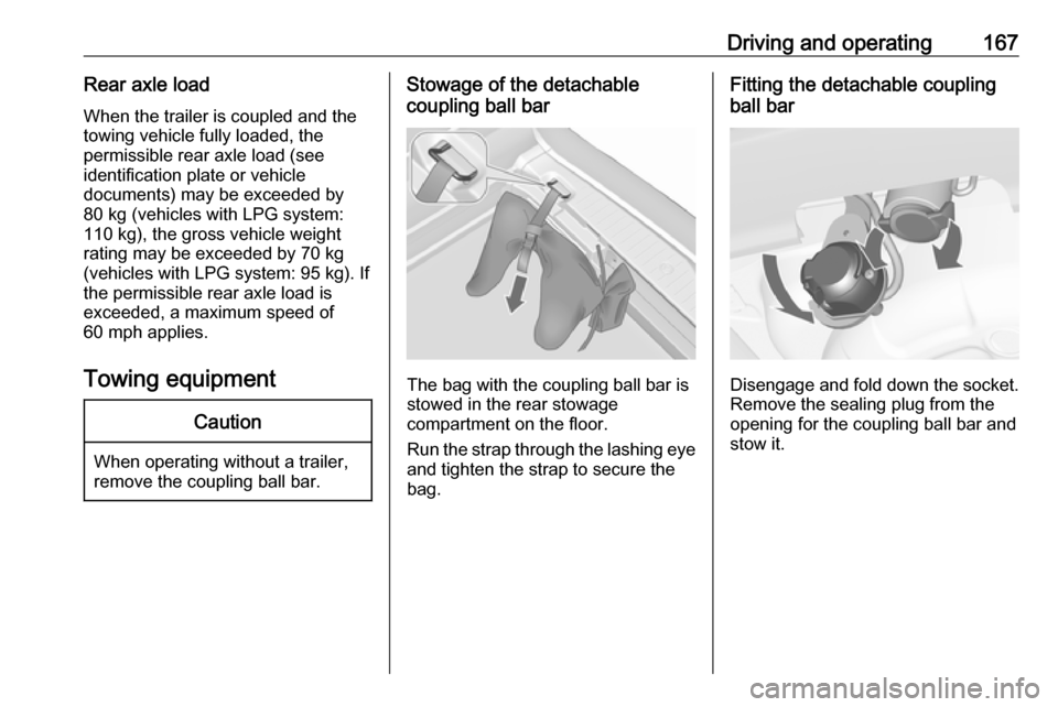
Stowage of the detachable
coupling ball bar
The bag with the coupling ball bar is
stowed in the rear stowage
compartment on the floor.
Run the strap through the lashing eye and tighten the strap to secure the
bag.
Fitting the detachable coupling
ball bar
Disengage and fold down the socket. Remove the sealing plug from the
opening for the coupling ball bar and
stow it.
Page 171 of 251
Driving and operating169Attach breakaway stopping cable to
eye.
Check that the coupling ball bar is
correctly installed
● Green marking on rotary knob must point towards green
marking on coupling ball bar.
● There must be no gap between the rotary handle and the
coupling ball bar.
● The coupling ball bar must be firmly engaged in the opening.
● The coupling ball bar must be locked and the key removed.9Warning
Towing a trailer is permitted only
when a coupling ball bar is fitted correctly. If the coupling ball bardoes not engage correctly, seekthe assistance of a workshop.
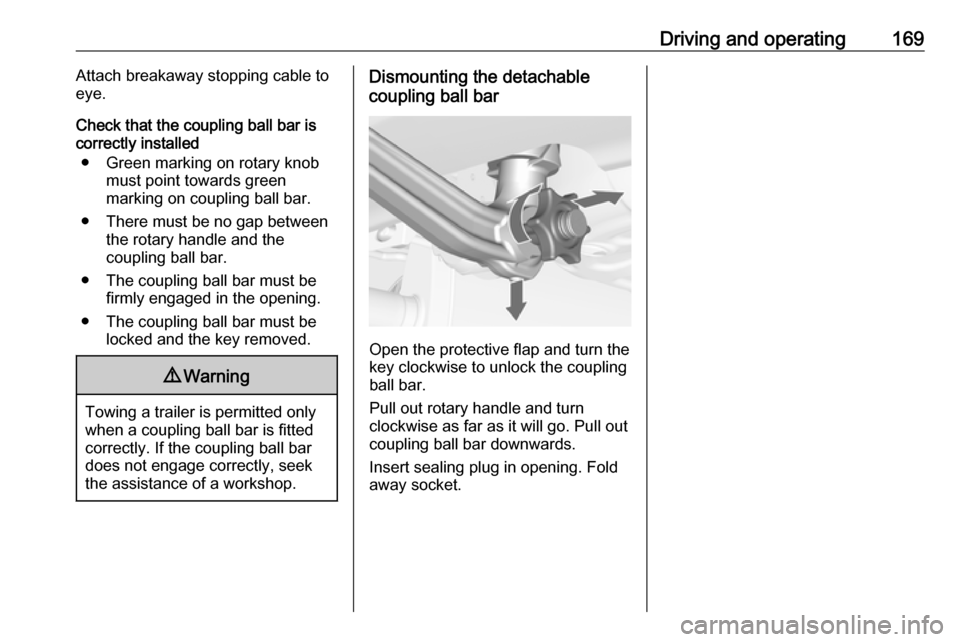
Dismounting the detachable
coupling ball bar
Open the protective flap and turn the
key clockwise to unlock the coupling
ball bar.
Pull out rotary handle and turn
clockwise as far as it will go. Pull out coupling ball bar downwards.
Insert sealing plug in opening. Fold away socket.
Page 172 of 251

170Vehicle careVehicle careGeneral Information...................171
Accessories and vehicle modifications .......................... 171
Vehicle storage ........................171
End-of-life vehicle recovery .....171
Vehicle checks ........................... 172
Performing work ......................172
Bonnet ..................................... 172
Engine oil ................................. 173
Engine coolant ......................... 174
Power steering fluid .................175
Washer fluid ............................ 175
Brakes ..................................... 175
Brake fluid ............................... 175
Vehicle battery ......................... 176
Diesel fuel system bleeding .....178
Wiper blade replacement ........178
Bulb replacement .......................179
Halogen headlights ..................179
Adaptive forward lighting .........181
Fog lights ................................. 183
Front turn signal lights .............183
Tail lights ................................. 184
Side turn signal lights ..............187
Number plate light ...................187Interior lights ............................ 188
Instrument panel illumination ...188
Electrical system ........................188
Fuses ....................................... 188
Engine compartment fuse box . 190
Instrument panel fuse box .......192
Load compartment fuse box ....193
Vehicle tools .............................. 194
Tools ........................................ 194
Wheels and tyres .......................195
Winter tyres ............................. 195
Tyre designations ....................195
Tyre pressure .......................... 196
Tyre pressure monitoring system .................................... 197
Tread depth ............................. 200
Changing tyre and wheel size . 200
Wheel covers ........................... 201
Tyre chains .............................. 201
Tyre repair kit .......................... 201
Wheel changing .......................206
Spare wheel ............................ 209
Jump starting ............................. 212
Towing ....................................... 213
Towing the vehicle ...................213
Towing another vehicle ...........214Appearance care .......................215
Exterior care ............................ 215
Interior care ............................. 217