light VAUXHALL MOKKA 2014 Workshop Manual
[x] Cancel search | Manufacturer: VAUXHALL, Model Year: 2014, Model line: MOKKA, Model: VAUXHALL MOKKA 2014Pages: 217, PDF Size: 5.9 MB
Page 165 of 217
Vehicle care163
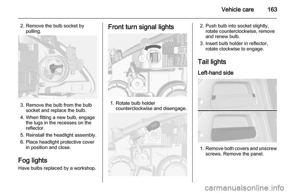
2. Remove the bulb socket bypulling.
3. Remove the bulb from the bulb socket and replace the bulb.
4. When fitting a new bulb, engage the lugs in the recesses on the
reflector.
5. Reinstall the headlight assembly.
6. Place headlight protective cover in position and close.
Fog lights
Have bulbs replaced by a workshop.
Front turn signal lights
1. Rotate bulb holder counterclockwise and disengage.
2. Push bulb into socket slightly,rotate counterclockwise, removeand renew bulb.
3. Insert bulb holder in reflector, rotate clockwise to engage.
Tail lights
Left-hand side
1. Remove both covers and unscrew
screws. Remove the panel.
Page 166 of 217
164Vehicle care
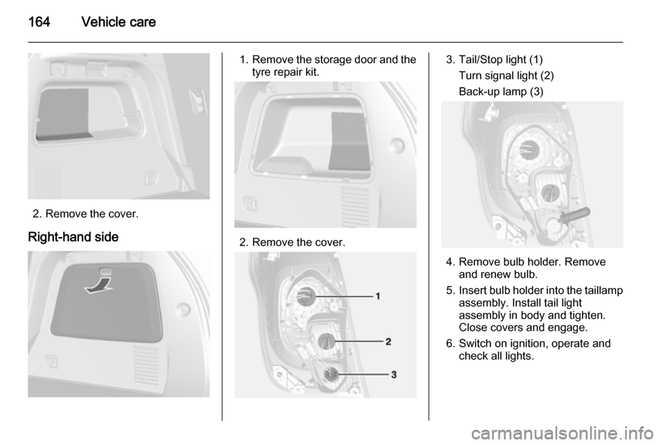
2. Remove the cover.
Right-hand side
1. Remove the storage door and the
tyre repair kit.
2. Remove the cover.
3. Tail/Stop light (1)
Turn signal light (2)Back-up lamp (3)
4. Remove bulb holder. Remove and renew bulb.
5. Insert bulb holder into the taillamp
assembly. Install tail light
assembly in body and tighten.
Close covers and engage.
6. Switch on ignition, operate and check all lights.
Page 167 of 217
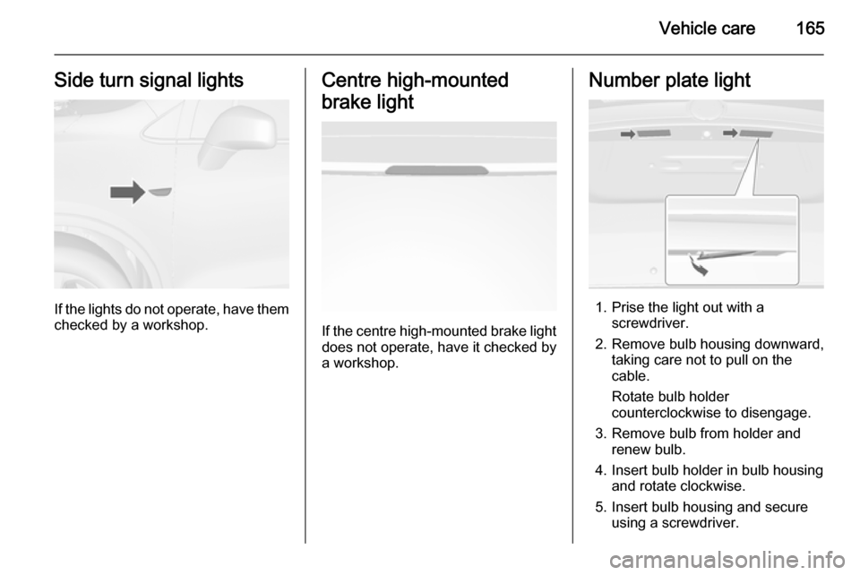
Vehicle care165Side turn signal lights
If the lights do not operate, have themchecked by a workshop.
Centre high-mounted
brake light
If the centre high-mounted brake light does not operate, have it checked by
a workshop.
Number plate light
1. Prise the light out with a screwdriver.
2. Remove bulb housing downward, taking care not to pull on thecable.
Rotate bulb holder counterclockwise to disengage.
3. Remove bulb from holder and renew bulb.
4. Insert bulb holder in bulb housing and rotate clockwise.
5. Insert bulb housing and secure using a screwdriver.
Page 168 of 217

166Vehicle careInterior lightsCourtesy lights 1. To remove it, prise the opposite side of the light switch using a flat-blade screwdriver.
2. Remove the bulb.
3. Replace the bulb.
4. Reinstall the light assembly.
Load compartment light
1. Prise the light out with a screwdriver.
2. Remove bulb.
3. Insert new bulb.
4. Install light.Electrical system
Fuses
Data on the replacement fuse must
match the data on the defective fuse.
In a box above the positive terminal of the battery are some main fuses. If
necessary have them changed by a
workshop.
Before replacing a fuse, turn off the
respective switch and the ignition.
A blown fuse can be recognised by its
melted wire. Do not replace the fuse
until the cause of the fault has been
remedied.
Some functions are protected by
several fuses.
Fuses may also be inserted without
existence of a function.
Notice
Not all fuse box descriptions in this
manual may apply to your vehicle.
When inspecting the fuse box, refer
to the fuse box label.
Page 169 of 217
Vehicle care167
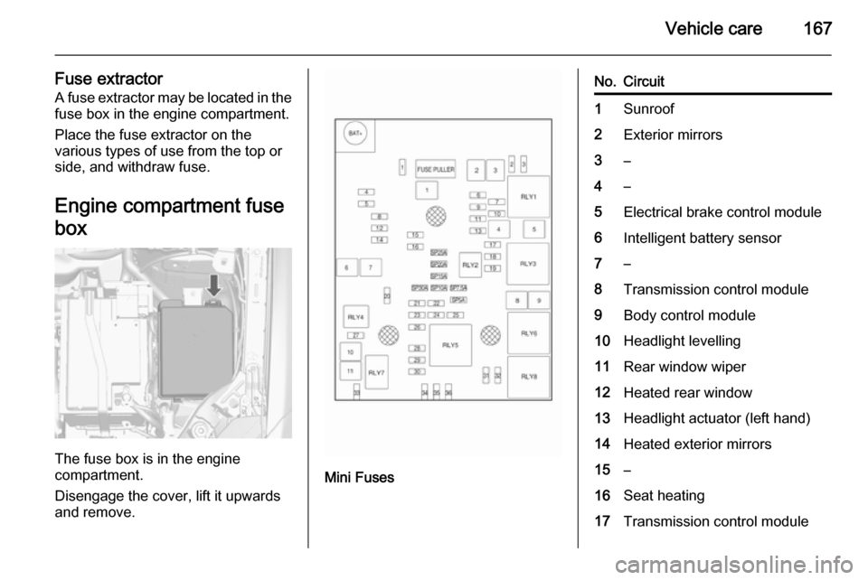
Fuse extractorA fuse extractor may be located in the fuse box in the engine compartment.
Place the fuse extractor on the
various types of use from the top or
side, and withdraw fuse.
Engine compartment fuse
box
The fuse box is in the engine
compartment.
Disengage the cover, lift it upwards
and remove.
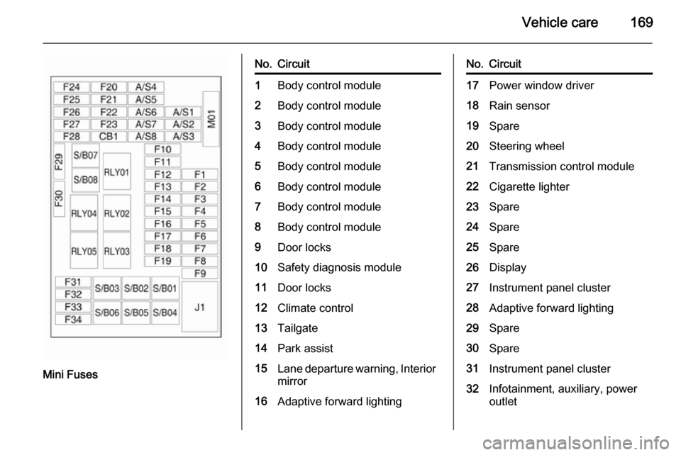
Mini Fuses
No.Circuit1Sunroof2Exterior mirrors3–4–5Electrical brake control module6Intelligent battery sensor7–8Transmission control module9Body control module10Headlight levelling11Rear window wiper12Heated rear window13Headlight actuator (left hand)14Heated exterior mirrors15–16Seat heating17Transmission control module
Page 171 of 217
Vehicle care169
Mini Fuses
No.Circuit1Body control module2Body control module3Body control module4Body control module5Body control module6Body control module7Body control module8Body control module9Door locks10Safety diagnosis module11Door locks12Climate control13Tailgate14Park assist15Lane departure warning, Interior
mirror16Adaptive forward lightingNo.Circuit17Power window driver18Rain sensor19Spare20Steering wheel21Transmission control module22Cigarette lighter23Spare24Spare25Spare26Display27Instrument panel cluster28Adaptive forward lighting29Spare30Spare31Instrument panel cluster32Infotainment, auxiliary, power
outlet
Page 173 of 217

Vehicle care171
No.Circuit1Seat, lumbar support, driver2Seat, lumbar support,
passenger3Amplifier4Trailer socket5All-wheel drive6Display7Spare8Trailer9Spare10Spare11Trailer12Navigation13Heated steering wheel14Trailer socket15Steering wheel16Water in fuel sensorNo.Circuit17Interior mirror18Spare
S/B Fuses
No.Circuit01Power seat driver02Power seat passenger03Trailer04Voltage converter05Battery06Headlight washer07Spare08Spare09SpareVehicle tools
Tools
Vehicles with tyre repair kit
The tools and tyre repair kit are in the
right side of the load compartment.
3 177.
Page 176 of 217

174Vehicle care
When the system detects a
malfunction, w will flash for approx.
one minute and then remain
continuously illuminated. This
sequence will continue upon
subsequent vehicle start-ups as long as the malfunction exists.
When w is illuminated, the system
may not be able to detect or signal low tyre pressure as intended.
Tyre Pressure Monitoring Operation The TPMS is designed to warn the
driver when a low tyre pressure
condition exists. TPMS sensors are mounted onto each tyre and wheel
assembly, excluding the spare tyre
and wheel assembly. The TPMS sensors monitor the air pressure in
the tyres and transmit the tyre
pressure readings to a receiver
located in the vehicle.
When a low tyre pressure condition is
detected, w illuminates. Stop as soon
as possible and inflate the tyres to the
recommended tyre pressure 3 172.
Additionally a warning message or a
warning code is displayed in the
Driver Information Centre 3 93.
The low tyre pressure control
indicator and a warning message or
code come on at each ignition cycle
until the tyres are inflated to the
correct tyre pressure.
TPMS Malfunction Indicator and
Message Code
The TPMS will not function properly if
one or more of the TPMS sensors are missing or inoperable. When the
system detects a malfunction, w
flashes for approx. one minute and then illuminates. Additionally a
warning message or code is
displayed.
The indication by the TPMS
malfunction indicator and a warning
message or code will come on at each ignition cycle until the problem iscorrected. Some of the conditions
that can cause these to come on are:
■ One of the tyres has been replaced
with the spare tyre which does not
have a TPMS sensor.
■ The TPMS sensor matching process was not done or not
completed successfully after
rotating the tyres. The malfunction
light and the warning message or
code should go off after
successfully completing the sensor
Page 177 of 217

Vehicle care175
matching process. See "TPMS
Sensor Matching Process" later in
this section.
■ One or more TPMS sensors are missing or damaged. The warning
message or code and the
malfunction light should go off
when the TPMS sensors are
installed and the sensor matching
process is performed successfully.
Consult your workshop for service.
■ Replacement tyres or wheels do not match the original equipment
tyres or wheels. Tyres and wheels other than those recommended
could prevent the TPMS from
functioning properly.
■ Operating electronic devices or being near facilities using radio
wave frequencies similar to the
TPMS could cause the TPMS
sensors to malfunction.
If the TPMS is not functioning
properly, it cannot detect or signal
a low tyre condition. Consult your
workshop for service if the TPMS
malfunction light and a warningmessage or code come on and stay
on.
TPMS Sensor Matching
Process
Each TPMS sensor has a unique
identification code. The identification
code must be matched to a new tyre/
wheel position after rotating the tyres
or replacing one or more of the TPMS
sensors. The TPMS sensor matching process should also be performed
after replacing a spare tyre with a
road tyre containing the TPMS
sensor.
The malfunction light and the warning
message or code should go off at the
next ignition cycle. The sensors are
matched to the tyre/wheel positions,
using a TPMS relearn tool, in the
following order: driver side front tyre,
passenger side front tyre, passenger
side rear tyre, and driver side rear.
Consult your workshop for service or
to purchase a relearn tool. There are
two minutes to match the first tyre/
wheel position, and five minutes
overall to match all four tyre/wheelpositions. If it takes longer, the
matching process stops and must be
restarted.
The TPMS sensor matching process
is:
1. Apply the parking brake.
2. Turn the ignition on.
3. Use the MENU button on the turn
signal lever to select the Vehicle
Information Menu in the Driver
Information Centre (DIC).
4. Use the thumbwheel to scroll to the tyre pressure menu.
5. Press the SET/CLR button to
begin the sensor matching
process. A message requesting
acceptance of the process should display.
6. Press the SET/CLR button again
to confirm the selection. The horn
sounds twice to signal the receiver is in relearn mode.
7. Start with the driver side front tyre.
8. Place the relearn tool against the tyre sidewall, near the valve stem.Then press the button to activate
the TPMS sensor. A horn chirp
Page 181 of 217

Vehicle care179
6.Unscrew valve cap from defective
tyre.
7. Screw the filler hose to the tyre valve.
8. The switch on the compressor must be set to J.
9. Connect the compressor plug to the power outlet or cigarette
lighter socket.
To avoid discharging the battery,
we recommend running the
engine.10. Set the rocker switch on the compressor to I. The tyre is filled
with sealant.
11. The compressor pressure gauge briefly indicates up to 6 bar whilstthe sealant bottle is emptying
(approx. 30 seconds). Then the
pressure starts to drop.
12. All of the sealant is pumped into the tyre. Then the tyre is inflated.
13. The prescribed tyre pressure should be obtained within
10 minutes. Tyre pressure
3 205 . When the correct pressure
is obtained, switch off the compressor.If the prescribed tyre pressure is
not obtained within 10 minutes,
remove the tyre repair kit. Move
the vehicle one tyre rotation.
Reattach the tyre repair kit and
continue the filling procedure for
10 minutes. If the prescribed tyre pressure is still not obtained, the
tyre is too badly damaged. Seek
the assistance of a workshop.
Drain excess tyre pressure with
the button over the pressure
indicator.
Do not run the compressor longer than 10 minutes.