lock VAUXHALL MOKKA 2015.5 Service Manual
[x] Cancel search | Manufacturer: VAUXHALL, Model Year: 2015.5, Model line: MOKKA, Model: VAUXHALL MOKKA 2015.5Pages: 229, PDF Size: 6.45 MB
Page 159 of 229

Driving and operating157
especially in the case of heavy
trailers. The vertical coupling load
should never fall below 25 kg.
Rear axle load The permissible axle loads (see
identification plate or vehicle
documents) must not be exceeded.
Towing equipmentCaution
When operating without a trailer,
remove the coupling ball bar.
Stowage of coupling ball bar
The bag with the coupling ball bar is
stowed in the rear stowage
compartment on the floor.
Place the strap through the lashing
eye, wrap around twice and tighten
the strap to secure the bag.
Fitting the coupling ball bar
Loosen both locking pins by using a
screwdriver.
Page 160 of 229

158Driving and operating
Remove both locking pins.
Pull cover forwards out of the
brackets and remove.
Disengage and fold down the socket. Remove the sealing plug from the
opening for the coupling ball bar and
stow it.
Checking the tensioning of the
coupling ball bar
■ Red marking on rotary knob must
point towards green marking on
coupling ball bar.
■ The gap between the rotary knob and the coupling ball bar must beapprox. 6 mm.
■ The key must be in position c.
Otherwise, the coupling ball bar must be tensioned before being inserted:
■ Unlock coupling ball bar by turning key to position c.
■ Pull out rotary knob and turn
clockwise as far as it will go.
Inserting the coupling ball bar
Page 161 of 229

Driving and operating159
Insert the tensioned coupling ball bar
in the opening and push firmly
upwards until it audibly engages.
The rotary handle snaps back into its
original position resting against the
coupling ball bar without a gap.9 Warning
Do not touch rotary handle during
insertion.
Lock the coupling ball bar by turning
the key to position e. Remove the key
and close the protective flap.
Eye for break-away stopping cable
Attach breakaway stopping cable to
eye.
Check that the coupling ball bar is correctly installed
■ Green marking on rotary knob must
point towards green marking on
coupling ball bar.
■ There must be no gap between the
rotary handle and the coupling ball
bar.
■ The coupling ball bar must be firmly
engaged in the opening.
■ The coupling ball bar must be locked and the key removed.9 Warning
Towing a trailer is permitted only
when a coupling ball bar is fitted correctly. If the coupling ball bardoes not engage correctly, seekthe assistance of a workshop.
Dismounting the coupling ball
bar
Page 162 of 229

160Driving and operating
Open the protective flap and turn the
key to position c to unlock the
coupling ball bar.
Pull out rotary handle and turn
clockwise as far as it will go. Pull out coupling ball bar downwards.
Insert sealing plug in opening. Fold away socket.
Attach the cover and insert both
locking pins.
Page 164 of 229

162Vehicle care
■ Open the bonnet, close all doorsand lock the vehicle.
■ Disconnect the clamp from the negative terminal of the vehicle
battery. Beware that all systems are not functional, e.g. anti-theft alarm
system.
Putting back into operation When the vehicle is to be put back into
operation:
■ Connect the clamp to the negative terminal of the vehicle battery.
Activate the electronics of the
power windows.
■ Check tyre pressure.
■ Fill up the washer fluid reservoir.
■ Check the engine oil level.
■ Check the coolant level.
■ Fit the number plate if necessary.
End-of-life vehicle
recovery
Information on end-of-life vehicle
recovery centres and the recycling of
end-of-life vehicles is available on ourwebsite, where legally required. Only
entrust this work to an authorised
recycling centre.
Gas vehicles must be recycled by a
service centre authorised for gas
vehicles.Vehicle checks
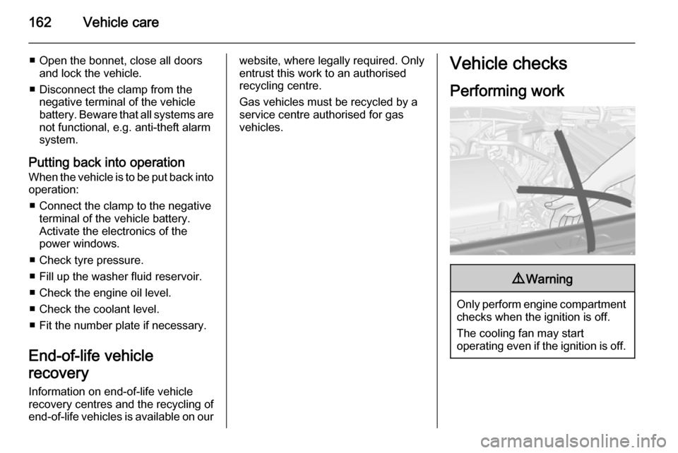
Performing work9 Warning
Only perform engine compartment
checks when the ignition is off.
The cooling fan may start
operating even if the ignition is off.
Page 173 of 229

Vehicle care171
3. When fitting a new bulb, engagethe lugs in the recesses on the
reflector.
4. Reinstall the headlight assembly. 5. Place headlight protective cover in position and close.
Sidelights
1. Remove the socket from the assembly by turning
anticlockwise.
2. Remove bulb socket from reflector.
3. Detach plug connector from bulb.
4. Remove bulb from socket.
5. Insert new bulb.
6. Plug connector onto bulb.
7. Insert socket in reflector.
8. Reinstall the assembly.
Xenon headlights
9 Danger
Xenon headlights work under
extremely high electrical voltage.
Do not touch. Have bulbs replaced by a workshop.
Cornering lights
1. Remove the protective cover.
Page 174 of 229

172Vehicle care
2. Remove the bulb socket bypulling.
3. Remove the bulb from the bulbsocket and replace the bulb.
4. When fitting a new bulb, engage the lugs in the recesses on the
reflector.
5. Reinstall the headlight assembly.
6. Place headlight protective cover in position and close.
Fog lights
Have bulbs replaced by a workshop.
Front turn signal lights
1. Rotate bulb holder anticlockwise and disengage.
2. Push bulb into socket slightly,rotate anticlockwise, remove and
renew bulb.
3. Insert bulb holder in reflector, rotate clockwise to engage.
Tail lights
Left-hand side
1. Remove both covers and unscrew
screws. Remove the panel.
Page 176 of 229

174Vehicle careSide turn signal lights
If the lights do not operate, have themchecked by a workshop.
Centre high-mounted
brake light
If the centre high-mounted brake light does not operate, have it checked by
a workshop.
Number plate light
1. Prise the light out with a screwdriver.
2. Remove bulb housing downwards, taking care not to pull
on the cable.
Rotate bulb holder anticlockwise
to disengage.
3. Remove bulb from holder and renew bulb.
4. Insert bulb holder in bulb housing and rotate clockwise.
5. Insert bulb housing and secure using a screwdriver.
Page 179 of 229

Vehicle care177
No.Circuit18Engine control module19Fuel pump20–21Cooling fan22–23Ignition coil/Engine control
module24Washer pump25Headlamp actuator (right hand)26Engine control module27–28Engine control module29Engine control module30Exhaust system31Left-hand high beam32Right-hand high beam33Engine control moduleNo.Circuit34Horn35Air conditioning system36Front fog lamp
J-cases Fuses
No.Circuit1Electrical brake control module2Front wiper3Cooling fan4Power terminal of instrument
panel fuse box5–6Fuel heater7–8Cooling fan9Cooling fanNo.Circuit10Engine control module/Glow
plug11Starter
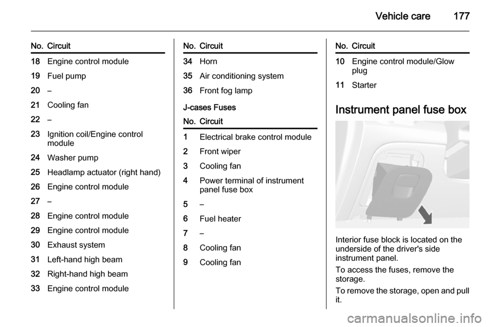
Instrument panel fuse box
Interior fuse block is located on the
underside of the driver's side
instrument panel.
To access the fuses, remove the
storage.
To remove the storage, open and pull it.
Page 189 of 229

Vehicle care187Tyre chains
Use tyre chains only on front wheels.
9Warning
Damage may lead to tyre blowout.
Tyre chains are permitted on tyres of
size 195/70 R16.
Always use fine mesh chains suitable
for sport utility vehicles that add no
more than 12 mm to the tyre tread and the inboard sides (including chain
lock).
On tyres of size 215/55 R18, special
snow chains are only permitted when
they are designed with a rotating
chain belt on the tyre tread, no chain
links on the wheel inboard sides and
the chains add no more than 12 mm
to the tyre tread. For further
information regarding correct snow
chain usage for this tyre size, contact a specialized vehicle parts dealer or
snow chain manufacturer.
Tyre chains are not permitted on tyres of size 205/70 R16, 215/65 R16,
215/60 R17 and 225/45 R19.
The use of tyre chains is not permitted
on the temporary spare wheel.
Tyre repair kit
Minor damage to the tyre tread can be
repaired with the tyre repair kit.
Do not remove foreign bodies from
the tyres.
Tyre damage exceeding 4 mm or that
is at tyre's sidewall cannot be repaired with the tyre repair kit.9 Warning
Do not drive faster than 50 mph.
Do not use for a lengthy period.
Steering and handling may be
affected.
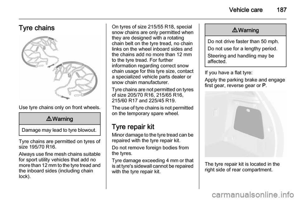
If you have a flat tyre:
Apply the parking brake and engage
first gear, reverse gear or P.
The tyre repair kit is located in the
right side of rear compartment.